
W1 - Heimtrainer TUNTURI - Kostenlose Bedienungsanleitung
Finden Sie kostenlos die Bedienungsanleitung des Geräts W1 TUNTURI als PDF.


| Produkttyp | Heimtrainer / Ergometer |
| Modell | W1 |
| Marke | Tunturi |
| Abmessungen (L x B x H) | 95 cm x 51 cm x 107 cm |
| Gesamtgewicht | 34 kg |
| Schwungradgewicht | 18 kg |
| Übersetzungsverhältnis | 1:3,25 |
| Widerstandsbereich | 25 W - 450 W |
| Widerstandseinstellung | stufenlos, über Drehknopf |
| Anzeigen | Leistung (W bei 50/60 U/min), Drehmoment (Nm), Trittfrequenz (0-200 U/min), Umdrehungszähler, Timer (1-60 Min), Energieverbrauchstabelle (kJ) |
| Sitzverstellung | höhenverstellbar, Neigung über Distanzscheiben |
| Lenkerverstellung | 3 Positionen, über Drehknöpfe |
| Rahmen | geschweißtes Stahlrohr, niedriger Schwerpunkt |
| Freilauf | ja |
| Bremsbelagmaterial | Standard-Reibbelag |
| Wartung Bremsbeläge | Wechsel bei Verschleiß, ca. alle mehrere hundert Stunden |
| Schmierung Kette | zweimal jährlich ölen |
| Kalibrierung | empfohlen jährlich, mit 5 kg Gewicht |
| Stoßdämpfer | fettbar, bei Vibration prüfen |
| Transport | rollbar (Bremse lösen), Tragegriff unter Sitz |
| Umgebungsbedingungen | kühl, trocken, staubfrei; nicht in feuchten Räumen |
| Ersatzteile verfügbar | ja, vollständige Explosionszeichnung mit Teilenummern |
Häufig gestellte Fragen - W1 TUNTURI
Benutzerfragen zu W1 TUNTURI
0 Frage zu diesem Gerät. Beantworten Sie die, die Sie kennen, oder stellen Sie Ihre eigene.
Eine neue Frage zu diesem Gerät stellen
Laden Sie die Anleitung für Ihr Heimtrainer kostenlos im PDF-Format! Finden Sie Ihr Handbuch W1 - TUNTURI und nehmen Sie Ihr elektronisches Gerät wieder in die Hand. Auf dieser Seite sind alle Dokumente veröffentlicht, die für die Verwendung Ihres Geräts notwendig sind. W1 von der Marke TUNTURI.
BEDIENUNGSANLEITUNG W1 TUNTURI
TUNTURI®
TUNTURI
ERGOMETER
OWNER'S MANUAL

natural_image
Black-and-white photo of a Tunturi stationary exercise bike with visible branding and front wheel (no text or symbols on the bike body itself)The TUNTURI ERGOMETER is a robust, reliable exercise cycle designed to help you improve, main-
tain and measure your physical fitness. With its versatile meter panel, it's ideal for testing and monitoring
your condition and thus makes it easy to follow an individualized training programme.
ASSEMBLY
Remove the cycle and its fittings from the package and assemble using the tools provided, as follows:
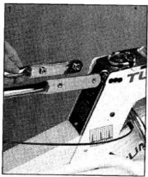
Remove the nuts from the bottom ends of the fork supporting the handlebars. Insert the fork between the frame and chrome meter panel as shown in Fig. 1.
Turn the handlebar support into the vertical position and slide into place (Fig. 2).
Insert the spacer (1), washer (2) and screw (3) into the lower hole on each side of the frame, as indicated in Fig. 3. Tighten with the wrench provided. Insert the triangular locking knob (4) with washer (5) into one of the three adjustment holes at each side and tighten lightly. Leave the final adjustment of the handlebars until the seat has been set to the correct height.
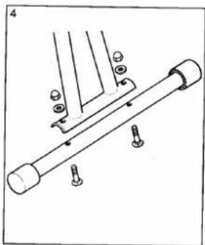
Fix rear support tube to legs as shown in Fig. 4.
Fit white plastic caps onto front legs as in Fig. 5.
Insert seat post into frame as shown and tighten locking knob lightly (Fig. 6).
natural_image
Close-up of a mechanical device with a handle and lever mechanism (no visible text or symbols)
natural_image
Close-up of a white bicycle's front wheel with visible brand name 'TANTURI' and 'JIMURI' on the side (no additional text or symbols)
natural_image
Technical line drawing of a mechanical assembly with bolts and a rod (no text or symbols)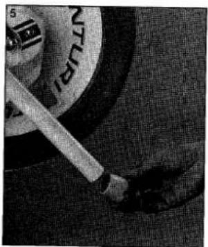
natural_image
Close-up of a hand holding a small object, possibly a tool or device, with no visible text or symbols.
natural_image
Close-up of a person holding a rifle with visible stock, no text or symbols presentUnscrew the green plugs from the right-hand crank and pedal. Screw the pedal onto the crank, tightening clockwise. Unscrew the red plugs from the left-hand crank and pedal and screw the pedal into place, tightening anti-clockwise (Fig. 7). The right and left pedals are also distinguished from each other by the letters R and L stamped on the underside of the pedal shaft. Clean the braking surfaces of the flywheel (see Maintenance) and make sure that all screws and nuts are securely tightened before using the cycle.

natural_image
Close-up of hands holding a black mechanical device with a handle, no visible text or symbolsOPERATION
Adjustment of seat height Set the seat height so that the ball of the foot reaches the pedal with the leg almost straight and the pedal at the bottom of its rotation (Fig. 8). To adjust the seat angle, place the required number of spacers between the seat and seat support.
Adjustment of handlebars Loosen the triangular locking knobs and set the distance between handlebars and seat to one of the three possible positions, so that the user can pedal comfortably with the arms almost straight. Tighten the knobs securely.
Regulation of pedaling resistance / To increase resistance, turn the knob on the handlebars clockwise (+), to decrease resistance anticlockwise (-). Do not force the knob beyond the minimum and maximum positions as this may damage the regulating mechanism (Fig. 9).
Timer
To time your workout, set the timer, e.g. to 15 min, by turning it clockwise. The bell will ring when your workout time is up (Fig. 11).

natural_image
Person performing a balance exercise on a stationary bike (no visible text or symbols)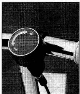
natural_image
Close-up of a mechanical component with a circular head and lever mechanism (no visible text or symbols)Pedalling
It is best to begin pedalling at low resistance. After a few minutes' warming up, you can gradually increase resistance. To calculate exactly the force you are exerting when pedalling, follow the rev counter and keep your speed at a steady 50 or 60 revolutions per minute. You can then read off the corresponding power in watts from the meter: The right-hand scale shows your pedalling power at 60 rpm, that on the left at 50 rpm.
If you want to know your pedalling power at other rpms, use the Nm table (crank moments in Newton metres) and the conversion table at the front of the meter panel. This shows the force you are applying at 40, 70 and 80 rpm. For example, if crank moment is 30 Nm and pedalling speed 70 rpm, total pedalling power applied is 220W (Figs 10 and 11).
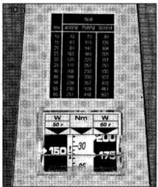
Energy consumption table (kJ) The table below the timer (fig. 11) shows total energy expenditure in kilojoules. For example, pedalling at 100 W for 20 minutes, your total energy consumption is 480 kJ.
To translate the energy expended into kilocalories, divide by 4.2. For

natural_image
Top-down view of a vintage mechanical device with dual gauges and control knobs (no visible text or symbols)more detailed information on physical fitness and how exercise affects your fitness, or if you want to plan your own training programme, consult the Tunturi Fitness Guide and Fitness Measurement Guide, both of which give information about efficient exercising.
TRANSPORT AND STORAGE
The Tunturi Ergometer is easy to move by rolling it along the floor (after releasing the brake) as shown in Fig 12. To lift the cycle, hold it under the seat and meter panel, which is shaped to give a good grip (Fig. 13).
To avoid damage or malfunctioning, keep the Tunturi Ergometer in a cool, dry place free of dust. It is not recommended to use the cycle in damp conditions as the flywheel may rust, causing faulty operation.

natural_image
Person in protective suit standing beside a wheeled cart with a black head (no visible text or symbols)
natural_image
Black-and-white photo of a Tunturi exercise bike with visible support structure and body model (no text or symbols)MAINTENANCE
The Tunturi Ergometer is extremely robust and made to withstand continuous hard use. To keep it working efficiently and in good condition, it is important to perform certain simple maintenance and adjustment procedures at regular intervals:
Adjustment of resistance cable
If the resistance control knob has too much play (turns freely more than one rotation) without giving maximum resistance, tighten the resistance cable. To do this, turn the round nut at the lower end of the cable in a clockwise direction (see Fig. 14). When properly adjusted, the control knob should not turn freely more than 1/2 - 1 rotation.
Brake pads
In normal use, the brake pads will withstand several hundred hours of use. Wear on the pads does not affect the accuracy of the meter, as the reading depends only on the amount of pressure exerted on the pads. The pads should be changed when the gripping surface is almost completely worn away.
Changing brake pads
Loosen the cable by turning the control knob on the handlebars to minimum resistance. Loosen the nut (14.1) and separate the arms of the brake caliper (14.2). Remove the worn pads and insert new pads. Retighten the nut as shown in Fig. 14.
Flywheel braking surfaces
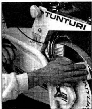
Before use it is advisable to clean the braking surfaces of the flywheel. To do this, rotate the flywheel by turning one pedal crank and hold a piece of emery paper against the surface (Fig. 15).

natural_image
Close-up of hands using a tool to adjust or install a component, no visible text or symbolsChains
The chain should be lubricated twice a year. Remove the right-hand chain guard and apply oil, preferably with a spray. Wipe away any excess oil.
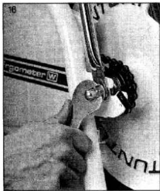
If the chain is noisy, it is either too tight or too loose. To adjust it, loosen the locking nuts on the flywheel axle and move the flywheel forward or backward as necessary (Fig. 16). After tightening the nuts, make sure the chain is properly aligned. Also be careful not to let the speedometer drive rotate when retightening the nuts, as this might result in damage to the speedometer cable.
natural_image
Close-up of hands operating a Tunturi motorcycle wheel (no visible text or symbols)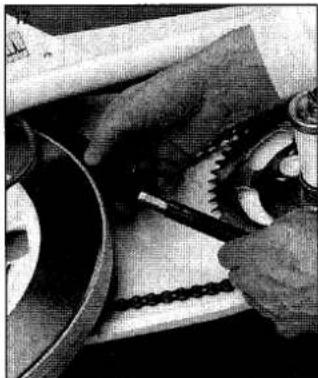
natural_image
Close-up of hands using a tool to work on a mechanical component (no visible text or symbols)Shock absorber
If the watt meter vibrates, check the shock absorber (Fig. 17). There should be a layer of grease between the sliding parts of the absorber. Apply some thick vaseline and rotate and slide the parts against each other before assembly.
Seat lock
Grease the threads of the seat locking nut twice a year.
Professional use
If the Tunturi Ergometer is used professionally, the above maintenance procedures should be carried out more frequently.
CALIBRATION
The Tunturi Ergometer is designed for accurate physiological measurements and is equipped with a balance mechanism for measuring crank moment and energy expenditure. The accuracy of this mechanism may be disturbed, e.g. during transport, and should therefore be checked from time to time, at least once a year if very accurate measurements are required. To do this, proceed as follows:
Support the cycle on two chairs as shown in Fig. 18. Loosen the brake cable and suspend a 5 kg weight by means of an S-shaped steel hook from the hexagonal nut of the brake caliper. The pointer of the meter should then be at the level of the arrows on the scale (28 Nm), as shown in Fig. 10.
To eliminate the friction effect of the brake system, gently tap the brake pad. It is important to read the scale at right angles to ensure complete accuracy.

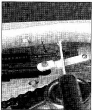
To perform any adjustments required, remove the left-hand chain guard. The mechanism can then be adjusted by turning the regulating screw shown in Fig. 19.
natural_image
Black-and-white photo of a vintage aircraft with visible cockpit, wings, and engine (no text or symbols)WHAT TO DO IF...
| FAULT | REASON | ACTION |
| Handlebars not secure | Locking nuts loose | Tighten lower screws with wrench, triangular knobs by hand |
| Brake not operating | Round nut at lower end of resistance cable loose | Thread nut into place and adjust cable tension. See Maintenance/ Adjustment of resistance cable |
| Resistance control knob turns freely more than one rotation | Incorrect adjustment of resistance cable | Adjust tension of cable. See Maintenance/Adjustment of resistance cable |
| Watt meter does not reach maximum reading | Incorrect adjustment of brake cable | Adjust tension of cable as above |
| Undue noise from brake pads | Dirt or rust on braking surface of flywheel | See Maintenance of flywheel braking surfaces |
| Pedal not secure | Pedal has worked loose from crank | Tighten pedal onto crank with wrench. See Assembly |
| Seat not secure | Locking nut not tightening sufficiently | Grease threads and tighten by hand |
| Undue noise from chain | Chain dryChain too tightChain out of alignment | Remove right-hand chain guard extension and lubricate chain Loosen flywheel axle nuts and move flywheel back slightly Remove right-hand chain guard and its extension. Loosen flywheel axle nuts and adjust position of flywheel until chain is aligned |
| Chain catches on guards | Chain loose or too close to guard | Loosen flywheel axle nuts and move flywheel forward |
| Watt meter scale vibrates | Rust or dirt on flywheel surfaceLack of grease in shock absorber | Clean flywheel. See Maintenance/Flywheel braking surfaces Apply some thick grease. See Maintenance/Shock absorber |
| Speedometer vibrates | Speedometer drive (part no 123) turned to wrong position | Open left-hand chain extension and make sure that speedometer cable is not warped |
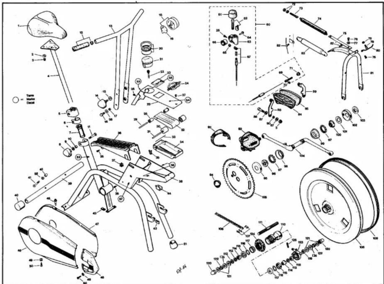
SPARE PARTS
| Item | Part N:o | Item | Part N:o | Item | Part N:o | Item | Part N:o | Item | Part N:o |
| 1 | 153.102.81 | 25 | 173.100.78 | 51 | 533.152.85 | 79 | 652.164.72 | 104 | 352.100.68 |
| 2 | 62.0612.16 | 26 | 60.39.013.50 | 52 | 423.163.71 | 80 | 233.119.78 | 105 | 263.103.81 |
| 3 | 61.0610 | 27 | 60.05.010.19 | 53 | 423.172.81 | 81 | 373.100.78 | 106-107 | 252.049.11 |
| 4 | 153.154.81 | 28 | 533.106.78 | 54 | 423.173.81 | 82 | 653.161.70 | 107 | 252.000.11 |
| 5 | 173.112.83 | 29 | 343.107.78 | 55 | 423.171.78 | 83 | 233.108.70 | 108-126 | 303.100.68 |
| 6 | 513.204.82 | 30 | 533.105.78 | 56 | 423.167.77 | 84 | 373.116.83 | 108 | 303.101.68 |
| 7 | 533.122.83 | 31 | 343.106.78 | 57 | 423.187.82 | 85 | 373.117.83 | 109 | 323.10.68 |
| 8 | 653.104.79 | 32 | 233.118.78 | 58 | 62.0817.10 | 86 | 60.06.030.32 | 110-118 | 333.100..68 |
| 9 | 653.132.83 | 33 | 233.120.78 | 60 | 373.122.84 | 87 | 62.0614.10 | 111-114, | = item 120 |
| 10 | 523.104.81 | 34 | 173.105.78 | 61 | 533.128.84 | 88 | 373.119.84 | 120 | 343.100.68 |
| 11 | 653.172.83 | 35 | 643.103.78 | 62 | 653.174.84 | 89 | 373.120.84 | 114 | 521.120.60 |
| 12 | 213.102.85 | 36 | 173.108.82 | 63 | 503.115.84 | 90 | 523.101.70 | 115 | 521.129.60 |
| 13 | 203.104.80 | 37 | 503.101.79 | 64 | 663.103.81 | 92 pair | 363.132.87 | 116 | 520.000.00 |
| 14 | 653.165.80 | 38-39 | 103.102.82 | 65 | 651.206.80 | right | 363.133.87 | 117 | 521.123.60 |
| 15 | 653.131.82 | 39 | 103.106.77 | 66 | 533.108.80 | left | 363.134.87 | 118 | 651.108.60 |
| 16 | 651.177.68 | 40 | 533.151.85 | 67 | 223.128.84 | 93 | 363.131.84 | 119 | 651.107.60 |
| 17 | 523.102.71 | 41 | 60.08.035.40 | 69 | 223.119.82 | 94 | 493.120.80 | 120 | 651.105.60 |
| 18 | 233.127.80 | 42 | 61.0821 | 70 | 60.04.006.35 | 95 | 522.155.85 | 121 | 62.1022.25 |
| 19 | 233.126.80 | 43 | 651.900.70 | 71 | 651.203.77 | 96 | 522.158.85 | 122 | 523.104.81 |
| 20 | 233.141.79 | 44 | 533.102.70 | 72 | 61.0601 | 97 | 522.160.85 | 123 | 233.101.79 |
| 21 | 233.100.87 | 45 | 533.107.80 | 73 | 653.160.68 | 98 | 522.154.85 | 123* | 233.171.87 |
| 21* | 233.170.87 | 46 | 143.125.86 | 74 | 643.100.68 | 99 | 522.157.85 | 124 | 263.100.68 |
| 22 | 223.100.68 | 47 | 143.126.86 | 75 | 233.121.78 | 100 | 522.159.85 | 125 | 662.700.71 |
| 22* | 223.137.87 | 48 | 143.127.86 | 76 | 60.05.006.11 | 101 | 652.101.68 | 126 | 653.138.87 |
| 23 | 433.160.78 | 49 | 653.133.84 | 77 | 62.0511.10 | 102 | 522.156.85 | ||
| 24 | 423.104.81 | 50 | 60.42.016.59 | 78 | 61.0510 | 103 | 522.161.85 |
* "Pricol" speedo meter
TECHNICAL DATA
- length 95 cm
- width 51 cm
- height 107 cm
- total weight 34 kg
- weight of flywheel 18 kg
- gear ratio 1:3.25
-
robust welded tubular steel frame
– low centre of gravity giving stability -
free wheel ensuring safe pedalling
- infinitely variable pedalling resistance
- power range 25W - 450W
- meter showing pedalling power at 50 and 60 rpm
- table showing pedalling power applied at 40, 70 and 80 rpm
– meter showing crank moment in
newton metres
- meter showing pedalling speed (0 - 200 rpm) and crank revolutions (white figure changes every 100 revs)
- timer (1 - 60 min)
- table showing energy consumption in kilojoules (kJ) when time and applied pedalling power are known
DISCLAIMER
The information presented in this guide is given in good faith and is so to the best of our knowledge accurate, however everyone who uses this information in any way does so entirely at their own risk. Neither Tunturipyörä Oy, nor their agents or representatives can accept any responsibility for any damage or injury incurred as a result of information presented here, except under the terms of warranty of Tunturi products.
TUNTURI®
Manufacturer: Tunturipyörä Oy
20760 Piispanristi Finland
Tel. int. +358-21-603 III Telex 62 617 tuntu sf
Fax +358-21-603 323


Marke : TUNTURI
Modell : W1
Kategorie : Heimtrainer