
W2 - Heimtrainer TUNTURI - Kostenlose Bedienungsanleitung
Finden Sie kostenlos die Bedienungsanleitung des Geräts W2 TUNTURI als PDF.


| Produkttyp | Heimtrainer / Ergometer |
| Modell | Tunturi W2 |
| Abmessungen (L x B x H) | 95 x 58 x 111 cm |
| Gewicht | 41 kg |
| Schwungradgewicht | 18 kg |
| Übersetzungsverhältnis | 1:3,25 |
| Widerstandseinstellung | stufenlos über Drehknopf |
| Leistungsanzeige (bei 50/60 U/min) | 50–375 W (Skala) |
| Display | LCD: U/min, Gesamtumdrehungen, Restzeit, automatischer Wechsel |
| Pulsmessung | nicht vorhanden |
| Sitzverstellung | höhen- und neigungsverstellbar |
| Lenkerverstellung | höhenverstellbar |
| Stromversorgung | 2 x AA-Batterien (SUM-3/R6) |
| Zeituhr | einstellbar bis 9 Std. 59 Min., mit Signaltönen |
| Gesamtenergieverbrauch (kJ) | anzeigbar über Tabelle |
| Freilauf | ja, für sicheres Treten |
| Rahmen | robuster Stahlrohrrahmen |
| Transport | rollbar auf dem Schwungrad |
| Bremsbelag | austauschbar, verschleißt nach mehreren 100 Stunden |
| Kette | Nachspannen und Schmieren (jährlich) |
| Kalibrierung | über 5-kg-Gewicht und Prüfschraube |
| Hersteller | Tunturipyörä Oy, Finnland |
Häufig gestellte Fragen - W2 TUNTURI
Benutzerfragen zu W2 TUNTURI
0 Frage zu diesem Gerät. Beantworten Sie die, die Sie kennen, oder stellen Sie Ihre eigene.
Eine neue Frage zu diesem Gerät stellen
Laden Sie die Anleitung für Ihr Heimtrainer kostenlos im PDF-Format! Finden Sie Ihr Handbuch W2 - TUNTURI und nehmen Sie Ihr elektronisches Gerät wieder in die Hand. Auf dieser Seite sind alle Dokumente veröffentlicht, die für die Verwendung Ihres Geräts notwendig sind. W2 von der Marke TUNTURI.
BEDIENUNGSANLEITUNG W2 TUNTURI
OWNER'S MANUAL
natural_image
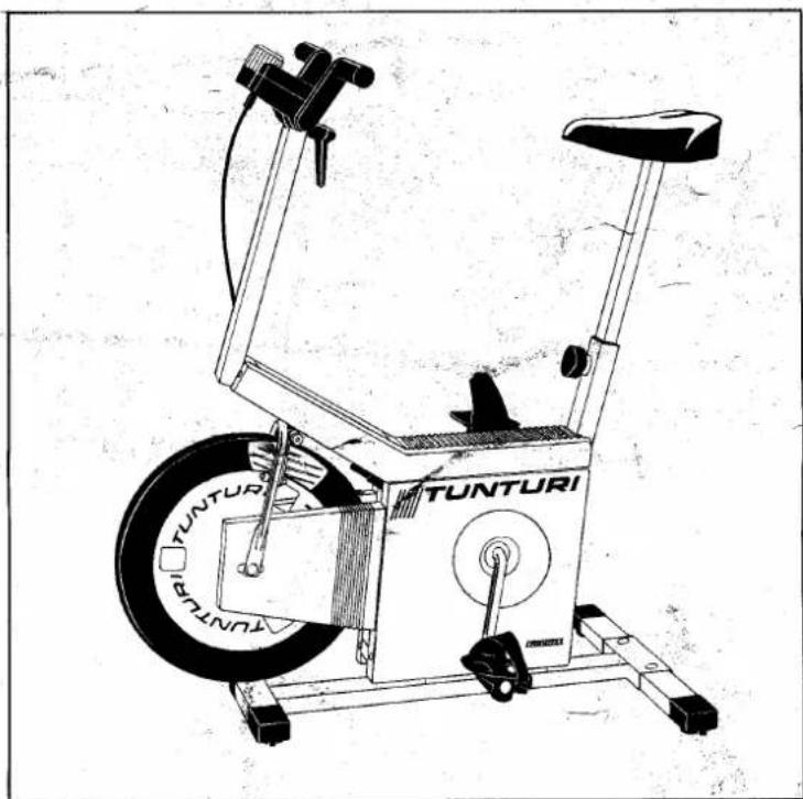
Line drawing of a Tunturi exercise bike with visible branding and wheel (no text or symbols beyond branding)TUNTURI ERGOMETER W2
The TUNTURI ERGOMETER W2 is a stylish exercise cycle designed for use in the modern home.
It facilitates aerobic exercises and helps you to maintain and
monitor your fitness at home or in a gymnasium.
Designing a programme to improve your fitness and following changes in your fitness will increase
your motivation in your exercise, which will give you a feeling of
physical and mental well-being.

ASSEMBLY AND PREPARATION FOR USE
When the cycle together with its fittings have been removed from the packing, you can assemble the cycle, using the enclosed tools, ready for use as follows:
-
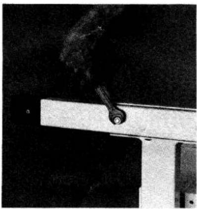
Mount the rear support of the Ergometer in place so that the heads of the bolts are on the upper side and the nuts and washers on the underside (Fig. 1).
-
Remove the green threaded plugs from the righthand crank and pedal. With the aid of the spanner attach the pedal to the crank, tightening clockwise (Fig. 2).
Remove the red threaded plugs from the lefthand crank and pedal and attach the pedal to the crank with the spanner. The lefthand pedal has a lefthand thread and must therefore be tightened anticlockwise. The pedals are distinguished from each other by having R (right) and L (left) stamped on their axles.
natural_image
Close-up of a hand holding a small mechanical component against a dark background (no visible text or symbols)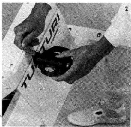
natural_image
Close-up of hands holding a black object with 'TURI' branding, placed on a tiled floor (no readable text or symbols beyond branding)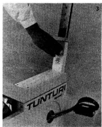
natural_image
Close-up of a hand operating a Tunturi tool with a small metal detector nearby (no visible text or symbols)- Instal the saddle and its support in position with the locking nut in the loose position and then tighten provisionally (Fig. 3).
natural_image
Black-and-white photo of a person wearing boots and holding a tablet (no visible text or symbols)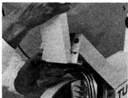
natural_image
Close-up of mechanical components with wires and a paper-like object (no visible text or symbols)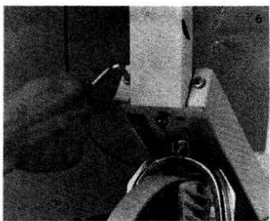
natural_image
Close-up of mechanical components with no visible text or symbols-
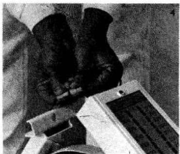
Join the leads from the handlebars and frame together and tuck them carefully into the handlebars (Fig. 4).
-
Raise the handlebar support carefully into the upright position at the front of the plastic meter panel (Fig. 5).
-
Insert the hexagonal nuts into their holes. Tighten the front nuts first and then the nut on the underside of the panel (Fig. 6).
-
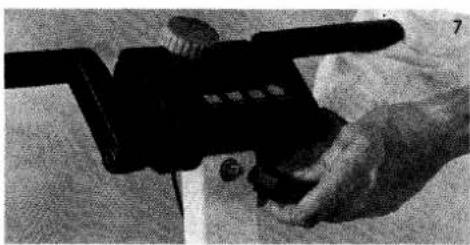
Remove the locking nut from the handlebars and turn the locking lever so that the bolt is in the right position (Fig. 7).
-
Check that all nuts and bolts are properly tight before using the cycle.
USE
Adjustment of saddle
Adjust the height of the saddle so that the ball of the foot reaches the pedal with the leg straight and the pedal in the lowered position (Fig. 8).
The angle of the saddle can be adjusted by placing the appropriate number of washers under the locking nuts of the saddle.
Adjustment of handlebars
Loosen the black locking lever on the handlebars and adjust the distance from the saddle so that you can pedal with your arms almost straight and the pedalling position feels comfortable. Check that both sections of the handlebars are equidistant from the meter panel. The turning circle of the handlebar locking lever can be adjusted by pulling the lever outwards and turning it in the desired direction.
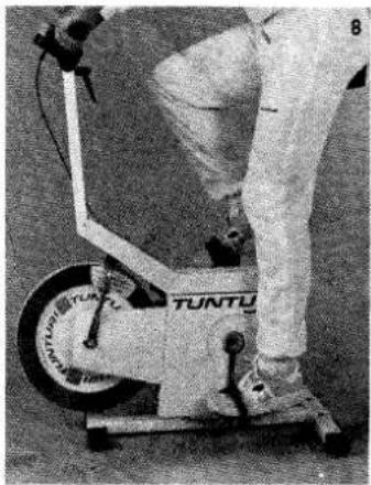
natural_image
Person performing a TUNTU exercise on a stationary bike (no visible text or symbols)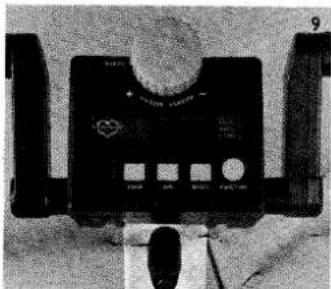
natural_image
Close-up of a black electronic device with control panel and display (no visible text or symbols)Pedalling
Begin pedalling at a low resistance. After warming up for a few minutes, you can gradually increase the pedalling resistance. If you wish to know your pedalling effect exactly, follow your speed on the rev counter and keep it at a steady 50 or 60 revolutions per minute. You can then read off the corresponding effect in watts from the effect meter. The scale on the righthand side indicates pedalling effect at 60 rpm and the scale on the lefthand side the effect at 50 rpm. A metronome will help you to keep your pedalling at a constant rate.
True pedalling effect in watts at 40, 70 or 80 rpm. For example, if you pedal at 70 rpm and the effect in watts as shown in the 50 rpm column is 200, then your true pedalling effect is 280 watts.
Adjustment of pedalling resistance
Pedalling resistance can be adjusted by means of the knob on the adjustment panel on the handlebars. Turning the knob in a clockwise direction (+) increases the resistance and in an anticlockwise direction (−) reduces the resistance (Fig. 9).
| Effect in watts at 50 rpm | 40 rpm | 70 rpm | 80 rpm |
| 50 | 40 | 70 | 80 |
| 75 | 60 | 105 | 120 |
| 100 | 80 | 140 | 160 |
| 125 | 100 | 175 | 200 |
| 150 | 120 | 210 | 240 |
| 175 | 140 | 245 | 280 |
| 200 | 160 | 280 | 320 |
| 225 | 180 | 315 | 360 |
| 250 | 200 | 350 | 400 |
| 275 | 220 | 385 | 440 |
| 300 | 240 | 420 | 480 |
Use of the regulation panel (Fig. 10)

LIQUID CRYSTAL DISPLAY
– revolutions per minute (rpm)
– total number of revolutions (revs)
– time remaining (time)
- SCAN automatic display change at 3.5-second intervals FUNCTION BUTTON
- to select desired function
- to turn off timer
– to return total revolutions and time to zero
EXERCISE TIMER: MINUTE BUTTON
- to set pedalling time in minutes
- to set pedalling time in hours
TIME BUZZER
- bleeps once when half the pedalling time has been reached and bleeps continuously when the set time is up
RESET BUTTON
EXERCISE TIMER: HOUR BUTTON
Pressing the FUNCTION button changes the display as follows: RPM → REV → TIME → SCAN → RPM
RPM = revolutions per minute, display 0 – 200 rpm, less than 30 rpm indicated by zero.
REV = total number of revolutions, display 0 – 9999 revolutions, running total
TIME = amount of exercise time remaining, maximum 9 h 59 min. Set the time that you wish to exercise by pressing the hour and minute buttons. To return the time to zero press the RESET button. The hour and minute settings increase each time you press the appropriate button.
Pressing the hour and minute buttons continuously increases the readings every 0.25 seconds.
When the hour display reaches "9" and the minute display "59", they then return to zero. The timer comes into operation five seconds after the time has been set.
When the exercise time remaining is less than one hour, the seconds are also displayed.
SCAN = automatic change of display at 3.5-second intervals - the SCAN sign is displayed in the top lefthand corner of the screen
The arrow indicates the function displayed at any one moment. To save the batteries, the display is automatically extinguished if the cycle is not used for five minutes. If you wish the display to operate once more, press the FUNCTION button or begin pedalling.
Warning: The liquid crystal display is sensitive to direct sunlight, high temperature and moisture. Do not expose the display to hard treatment. Wipe clean with a dry cloth.
| TOTAL ENERGY CONSUMPTION (kJ) | |||||
| 50 W | 100 W | 150 W | 200 W | 250 W | |
| 5 min | 60 | 120 | 180 | 240 | 300 |
| 10 min | 120 | 240 | 360 | 480 | 600 |
| 15 min | 180 | 360 | 540 | 720 | 900 |
| 20 min | 240 | 480 | 720 | 960 | 1200 |
| 30 min | 360 | 720 | 1080 | 1440 | 1800 |
| 60 min | 720 | 1440 | 2160 | 2880 | 3600 |
TRANSPORT AND STORAGE
The Tunturi Ergometer is best moved by rolling it along the floor on the flywheel as shown in the figure. The brake should of course be released when this is done (Fig. 11).
Lifting and carrying the Ergometer is best done by holding the Ergometer under the saddle at the back and under the handlebar support at the front.
To avoid damage to the Ergometer or adverse effects to its operation, it should be kept in a dry, dust-free place at an even temperature. Use in damp conditions is not recommended as this may cause faults in the electronics or the flywheel to rust and result in inaccuracy in operation.
SERVICE
The Ergometer is extremely robust and is built to withstand continuous hard use. To keep it in good condition and a high state of efficiency, it is important to perform certain simple service and adjustment operations at regular intervals as follows:
Adjustment of pedalling resistance cable
If the knob governing pedalling resistance has more than one turn of free play in it and maximum effect is not achieved, then the cable should be tightened. This is done by turning the round nut at the bottom end of the cable in a clockwise direction (Fig. 12). Properly adjusted the knob should have no more than 1/2 - 1 full turn of free play in it.
Brake pads
With normal use the brake pads will last for several hundreds of hours of use. Wear on the pads does not affect the accuracy of the meter since the reading on the meter depends only on the brake pressure. The brake pads should be changed when their friction surface has been almost entirely worn away.
Changing the brake pads
Loosen the cable by turning the adjustment knob on the handlebars to the 0-position. Undo the round nut (Fig. 12). Separate the brake arms from each other and remove the worn pads. Insert new pads. Tighten the cable as illustrated (Fig. 12).
Energy consumption table (kJ)
The table will tell you your total consumption of energy. For example, if you pedal for 20 minutes at an effect of 100 W, your total consumption of energy is 480 kJ (kilojoules).
If you want to know your energy consumption in kilocalories, divide by 4.2. If you wish for more detailed information about what physical fitness is, how exercise affects fitness or if you want to plan your own fitness programme and follow changes in your fitness, you should consult the Tunturi Fitness Guide and the Tunturi Fitness Measurement Guide, both of which give information about efficient exercise.
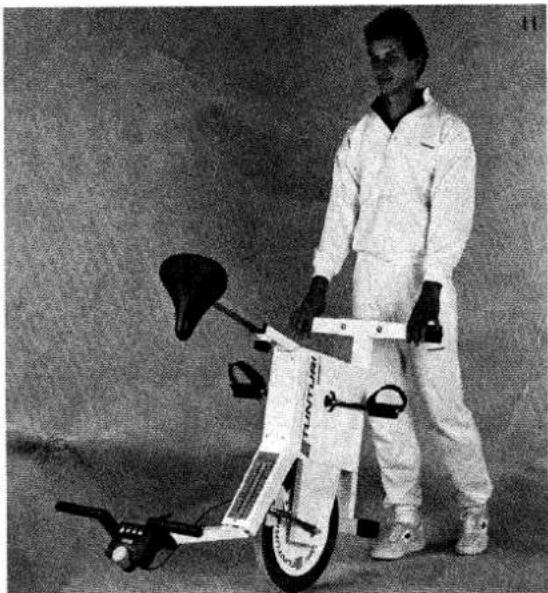
natural_image
Person in white suit standing beside a white electric scooter with visible wheels and headrest (no text or symbols)Flywheel brake surfaces
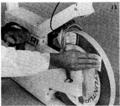
If there is dirt or patches of rust on the flywheel, clean the surfaces by rotating the flywheel by means of one pedal crank and pressing a piece of emery paper against the surface (Fig. 13).
Chains
Lubricate the chains with a few drops of oil once or twice a year. The best way to do this is with an aerosol spray. For lubrication remove the righthand plastic covers as follows: press the upper and lower rear corners of the front cover and pull it forwards free from the chain guard (Fig. 14). Undo the four Phillips screws and remove the plastic covers. Oil the chains and wipe away excess oil.
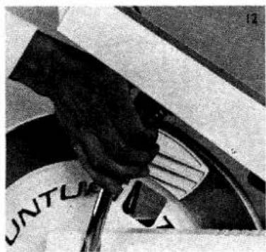
natural_image
Close-up of hands adjusting a cable or hose component (no visible text or symbols)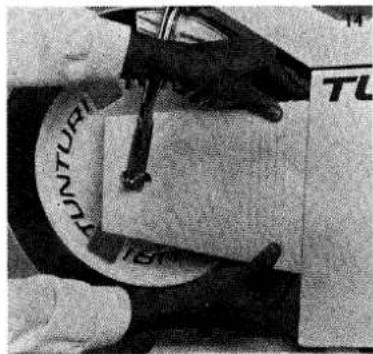
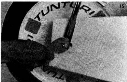
If the chains give rise to noise, they are either too tight or too loose. Adjust by undoing the locking nuts on the flywheel axle and moving the flywheel forwards or backwards as necessary. After tightening the flywheel nuts make sure that the chain runs true and that the pin governing the indicator mechanism moves freely in its groove (Fig. 15).
Changing the batteries
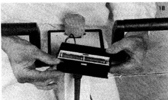
Undo the four screws on the underside of the regulating panel (Fig. 17) and remove the cover. Turn the panel upside down, open the battery container by pressing downwards and pulling the lid at the same time and then change the batteries (2 AA-size SUM-3 (R6)) (Fig. 18). Take care to ensure that the insulation on the lead is not broken when reassembling the panel.
natural_image
Close-up of a mechanical tool interacting with a surface, showing no visible text or symbolsCalibration
Since the Tunturi Ergometer W2 is designed for exact physiological measurements, it is equipped with a mechanism for measuring pedalling effect. The accuracy of this mechanism may be disturbed during transport, for example. The accuracy of the meter should therefore be checked from time to time.
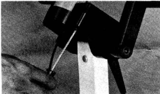
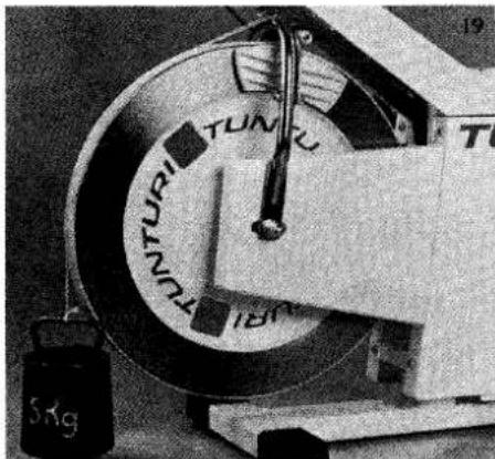
The brake cable is loosened and a 5 kg weight suspended by means of a noose of string attached to the checking screw on the brake shaft (Fig. 19). The effect meter should then indicate 200 W at 60 rpm.
Shock absorber
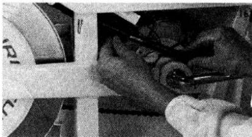
If the needle of the watt meter shakes, then the shock absorber should be checked to see that it is properly greased. Remove the lefthand pedal and open the lefthand chain guard as above. Remove the locking nuts on the cable tube, undo the tube and add enough thick grease so that the thicker part of the tube is at about the halfway position (Fig. 16).
natural_image
Close-up of hands using a tool to adjust or install a mechanical component (no visible text or symbols)Saddle locking nut
If the saddle is adjusted frequently, grease the threads from time to time.
natural_image
Close-up of hands holding a small electronic device with wires, no visible text or symbolsGymnasium use
If the Ergometer is used professionally or in a gymnasium, then the above service should be carried out more frequently depending on the degree of use.
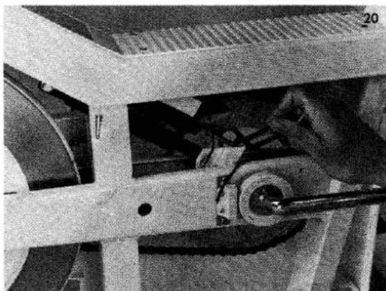
The friction effect of the meter cable can be eliminated by gently tapping the brake or by loosening the locking nut on the other end of the cable. For adjustment it is necessary to remove the left-hand chain guard; the mechanism can then be adjusted by means of the regulating screw shown (Fig. 20).
It is important to read the scale at right angles in order to achieve an exact reading.
natural_image
Close-up of mechanical components including a wheel and a tool, no visible text or symbols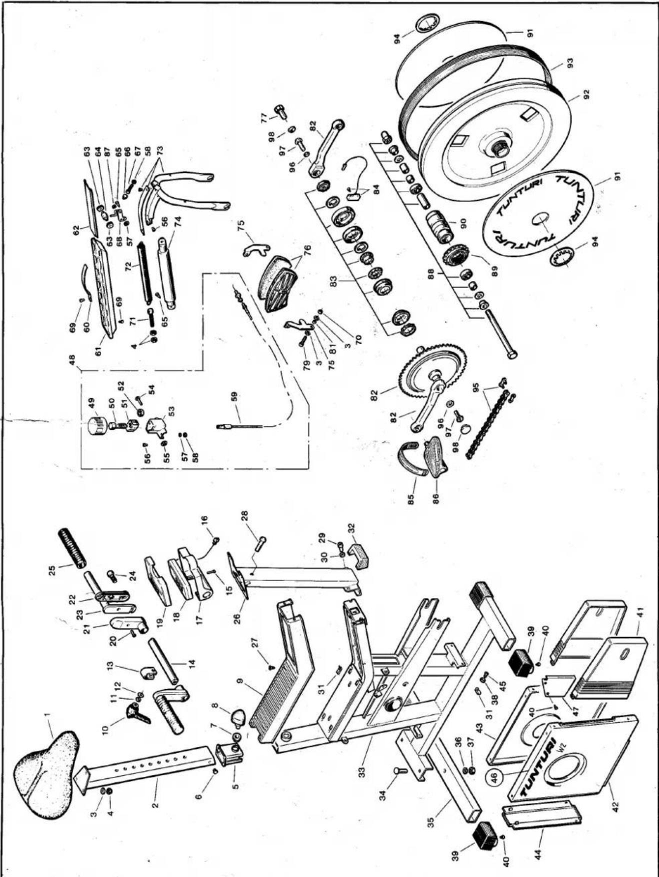
| Ref. No. | Part No. | Ref. No. | Part No. | Ref. No. | Part No. | Ref. No. | Part No. |
| 1 | 153.102.81 | 24 | 60.10.030.32 | 49 | 533.154.85 | 75 | 373.0002 |
| - | 153.108.87 (USA) | 25 | 213.105.85 | 50 | 653.176.85 | 76 | 373.118.83 |
| 2 | 153.156.85 | 26 | 103.122.86 | 51 | 533.526.84 | 77 | 60.12.025.03 |
| 3 | 62.0612.16 | 27 | 60.39.016.59 | 52 | 653.506.84 | 79 | 60.06.030.32 |
| 4 | 61.0601 | 28 | 60.08.040.42 | 53 | 503.119.85 | 81 | 523.101.70 |
| 5 | 533.158.85 | 29 | 60.08.016.34 | 54 | 663.502.84 | 82 | 353.0004 (incl. parts 96-98) |
| 6 | 533.157.85 | 30 | 653.139.87 | 55 | 651.206.80 | 83 | 523.120.89 |
| 7 | 533.156.85 | 31 | 651.900.70 | 56 | 60.05.012.11 | 84 | 233.154.85 |
| 8 | 653.507.84 | 32 | 173.121.86 | 57 | 62.0511.10 | 85 | 363.101.88 |
| 9 | 173.113.85 | 33 | 103.117.85 | 58 | 61.0501 | 86 | 363.100.88 (incl. 85) |
| - | 173.122.87 (USA) | 34 | 60.08.040.40 | 59 | 223.101.89 | 87 | 61.0510 |
| 10 | 653.508.87 | 35 | 103.115.83 | 60 | 233.158.86 | 88 | 333.107.89 |
| 11 | 653.132.83 | 36 | 62.0817.16 | 61 | 173.114.85 | 89 | 263.100.88 |
| 12 | 62.0817.20 | 37 | 61.0801 | 62 | 233.147.85 | 90 | 333.111.87 |
| 13 | 503.118.85 | 38 | 653.133.84 | 63 | 533.155.85 | 91 | 533.114.89 |
| 14 | 213.103.85 | 39 | 533.117.83 | 64 | 343.113.85 | 92 | 303.104.89 |
| 15 | 60.03.025.11 | 40 | 652.176.77 | 65 | 60.48.013.57 | - | 303.105.89 (incl. parts 89-95) |
| 16 | 403.101.87 | 41 | 143.121.85 | 66 | 683.101.85 | 93 | 323.100.68 |
| 17 | 173.116.85 | 42 | 143.123.85 (RH) | 67 | 60.05.025.11 | 94 | 673.105.87 |
| 18 | 233.152.85 | 43 | 143.124.85 (LH) | 68 | 233.148.85 | 95 | 252.049.11 |
| - | 406.140.00 (Battery) | 44 | 143.122.85 | 69 | 60.35.013.57 | 97 | 653.0002 |
| 19 | 173.115.85 | 45 | 60.42.016.59 | 70 | 61.0610 | - | 556.031.00 (Allen key) |
| 20 | 60.03.012.11 | 46 | 423.128.85 | 71 | 653.160.68 | - | 553.102.79 (Sandpaper) |
| 21 | 173.118.85 | 47 | 143.131.86 (RH) | 72 | 643.100.68 | - | 553.100.88 (Wrench) |
| 22 | 173.117.85 | - | 143.132.86 (LH) | 73 | 373.126.89 | ||
| 23 | 213.104.85 | 48 | 373.126.85 | 74 | 233.108.88 |
WHAT TO DO IF...
| FAULT Handlebars loose | POSSIBLE CAUSE Locking nuts loose | CORRECTIVE MEASURE Tighten the locking nuts at the bottom of the handlebar support and the locking lever on the handlebars |
| Brake does not work | Round nut at the bottom of the brake cable undone | Thread the nut into place and adjust the tension in the cable. See service/pedalling resistance cable |
| Brake adjustment knob has more than one turn of free play | Wrong adjustment of brake cable | Adjust tension of cable. See service/adjustment of pedalling resistance cable |
| Effect meter does not reach maximum reading | Wrong adjustment of brake cable | Adjust tension of cable. See service/adjustment of pedalling resistance cable |
| Undue noise from brake pads | Dirt or rust on friction surfaces of flywheel | See service/flywheel brake surfaces |
| Pedal loose | Pedal axle has worked loose | Tighten the pedal on to the crank with the spanner. See assembly/2 |
| Seat does not remain in place | Locking nut insufficiently tight | Undo the nut and grease the threads. Tighten by hand |
| Undue noise from chains | Chains dry Chains tight Chain not running true | Remove righthand chain guard and lubricate chain Loosen locking nuts on flywheel axle and move flywheel backwards slightly Remove righthand chain guard. Loosen locking nuts on flywheel axle and adjust position of flywheel so that chain runs true |
| Chains catch on chain guards or frame | Chains loose or too close to chain guard | Undo flywheel locking nuts and move flywheel forwards |
| Needle of effect meter trembles | Dirt or rust on flywheel | Clean flywheel. See service/flywheel brake surfaces |
| No display on meter panel | Batteries dead The screws of the meter panel are too tight | Change batterier (2 AA-size batteries) Loosen the screws |
natural_image
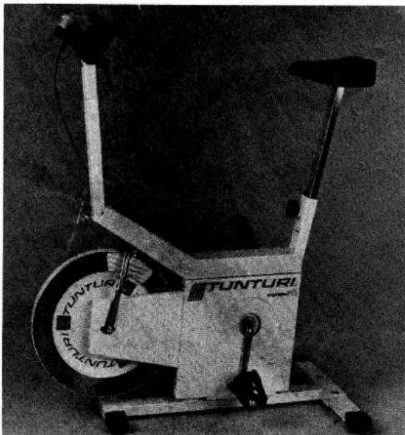
Exterior view of a Tunturi exercise bike (no signage or text visible on the vehicle itself)CONSTRUCTION AND TECHNICAL SPECIFICATIONS
- length 95 cm
- width 58 cm
- height 111 cm
- weight 41 kg
- weight of flywheel 18 kg
- gear ratio 1:3.25
- strong steel tube frame
- low centre of gravity – the cycle will not easily topple
- freewheel ensures safe pedalling
- infinitely variable adjustment of pedalling resistance
– effective range of display scale 50 W – 375 W
– clear display of pedalling effect at 50 and 60 rpm
– liquid crystal display: pedal revolutions per minute, total number of revolutions, time and automatic display change - time buzzer
- adjustable seat height
- adjustable handlebars
Manufacturer:
Tunturipyörä Oy
SF-20760 PIISPANRISTI, Finland
Tel. +358-21-603 111, telex 62617 Telefax +358-21-603 323

Tunturi – the fitness experts
PRINTED IN FINLAND BY PAINOPRISMA OY 11.90.2000


- OWNER'S MANUAL
- TUNTURI ERGOMETER W2
- ASSEMBLY AND PREPARATION FOR USE
- USE
- Adjustment of saddle
- Adjustment of handlebars
- Pedalling
- Adjustment of pedalling resistance
- LIQUID CRYSTAL DISPLAY
- RESET BUTTON
- EXERCISE TIMER: HOUR BUTTON
- TRANSPORT AND STORAGE
- SERVICE
- Adjustment of pedalling resistance cable
- Brake pads
- Changing the brake pads
- Flywheel brake surfaces
- Chains
- Changing the batteries
- Calibration
- Shock absorber
- Saddle locking nut
- Gymnasium use
- CONSTRUCTION AND TECHNICAL SPECIFICATIONS
Marke : TUNTURI
Modell : W2
Kategorie : Heimtrainer