PC3 - Büro Piranha - Kostenlose Bedienungsanleitung
Finden Sie kostenlos die Bedienungsanleitung des Geräts PC3 Piranha als PDF.


Benutzerfragen zu PC3 Piranha
0 Frage zu diesem Gerät. Beantworten Sie die, die Sie kennen, oder stellen Sie Ihre eigene.
Eine neue Frage zu diesem Gerät stellen
Laden Sie die Anleitung für Ihr Büro kostenlos im PDF-Format! Finden Sie Ihr Handbuch PC3 - Piranha und nehmen Sie Ihr elektronisches Gerät wieder in die Hand. Auf dieser Seite sind alle Dokumente veröffentlicht, die für die Verwendung Ihres Geräts notwendig sind. PC3 von der Marke Piranha.
BEDIENUNGSANLEITUNG PC3 Piranha
COMPUTER DESK ASSEMBLY INSTRUCTIONS
Thank you for choosing to purchase from Piranha Furniture We trust everything is as expected, however if there are ANY issues at all or you have further questions, please don't hesitate to email us and we will resolve the matter as quickly as possible:
United Kingdom: sales@piranhafurniture.com
Rest of EU: info@piranhaeurope.com
You can contact us through our website wherepicanhalfatsotfine.comfull range of products.
Please read the assembly instructions carefully before the installation
Retain all packaging as, if required, goods must be returned packed in the original cartons.
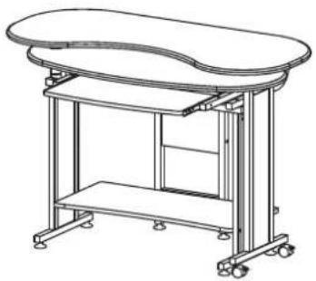
natural_image
Line drawing of a modern office desk with curved top and horizontal legs, no text or symbols presentMODEL PC3M
General Care:
Keep furniture out of direct sunlight. Use mats and coasters to protect surfaces.
Do not place hot or wet items directly onto unprotected surfaces.
Cleaning:
Wipe surfaces with a clean damp (not wet) cloth then dry with a clean lint free cotton cloth.
Glass surfaces may be polished with window or other glass cleaning liquids.
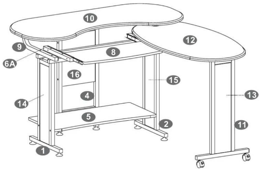
■PARTS LISTPARTS LIST
text_image
Technical diagram of a dual-plate office setup with numbered components and labeled parts1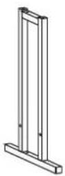 | 2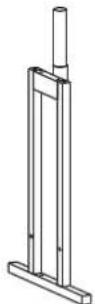 | 3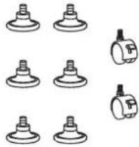 | 4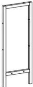 |
5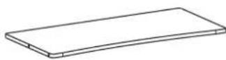 | 6A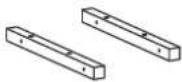 | 7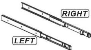 | 8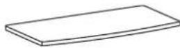 |
| 6B | |||
9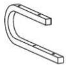 | 10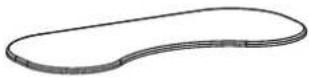 | 11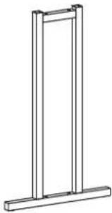 | 12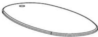 |
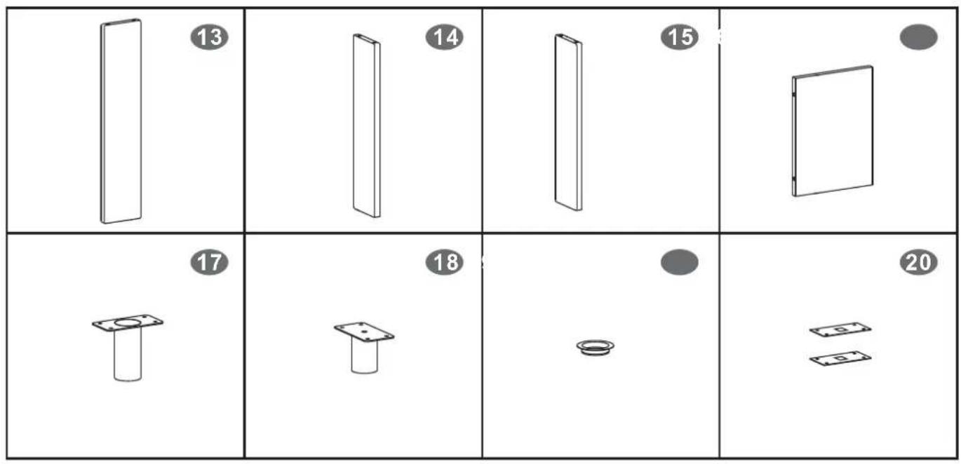
text_image
13 14 15 17 18 20■SCREWS LIST SCREWS LIST
| PART | QTY. | ITEM PART QTY. | ITEM |
| A | 4 | 6X35 MM | |
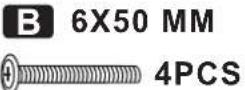
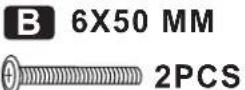
| B | 6 | 6X50 MM | |
| C | 2 | 6X30 MM | |
| D | 4 | 4X30 MM | |
| E | 20 | 4X14 MM | |
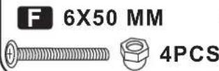
| F | 4 | 6X50 MM |
| G | 2 | 5X70 MM | |
| H | 14 | 5X40 MM | |
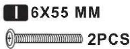
| I | 2 | 6X55 MM | |
| J | 2 | 6X20 MM | |
| 1 | |||
| 1 |
natural_image
Two metallic screw fasteners with mounting holes, one with a plus symbol and the other with a circular opening (no text or labels visible)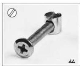
natural_image
Close-up of a metallic screw with a cross-shaped end, shown against a plain background (no text or symbols)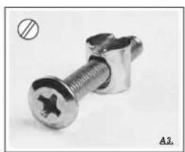
natural_image
Close-up of a metallic screw with a hole and mounting bracket (no text or symbols visible)
natural_image
Close-up of a wooden door with a knob and circular button, labeled B1 (no readable text or symbols beyond basic markings)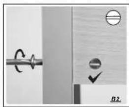
natural_image
Pure mechanical diagram showing a rotating shaft and a rectangular block with circular elements, no text or symbols present.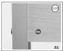
natural_image
Close-up of a wooden door with two circular holes and a side panel (no text or symbols visible)■ASSEMBLY STEPS:ASSEMBLY STEPS:
1
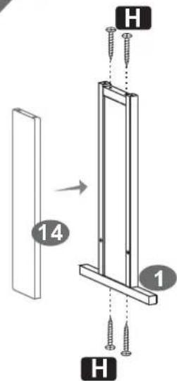
text_image
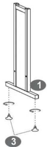
H 14 1 H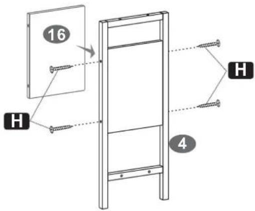
text_image
16 H 4 H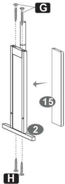
text_image
G 15 2 H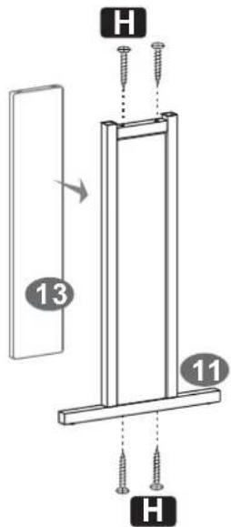
text_image
H 13 11 H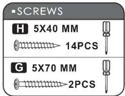
text_image
■SCREWS H 5X40 MM 14PCS G 5X70 MM 2PCS2
text_image
Diagram showing a structural frame with three labeled components and directional arrows indicating rotation or movement.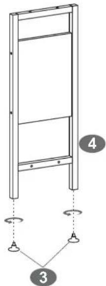
text_image
Diagram of a ladder structure with numbered components and supporting fixtures, labeled 3 and 4.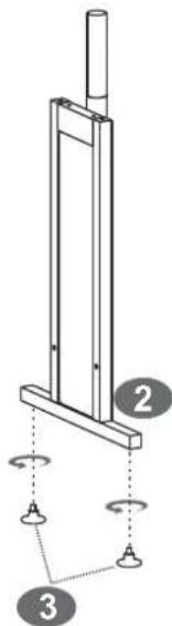
text_image
Diagram of a mechanical device with labeled components and rotational indicators3

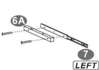
text_image
6A 7 LEFT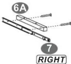
text_image
6A 7 RIGHT■ SCREWS

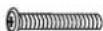
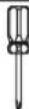
4
text_image
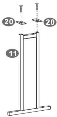
20 20 11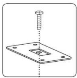
natural_image
Technical diagram showing a screw inserted into a square plate with a central hole (no text or symbols)5
text_image
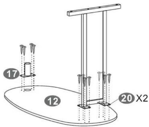
17 12 20 X2■ SCREWS
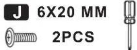
■ SCREWS
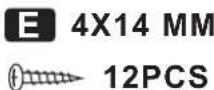
6
text_image
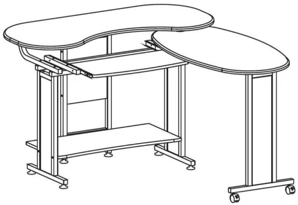
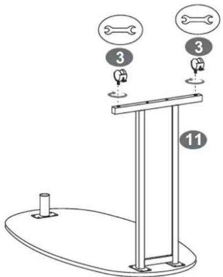
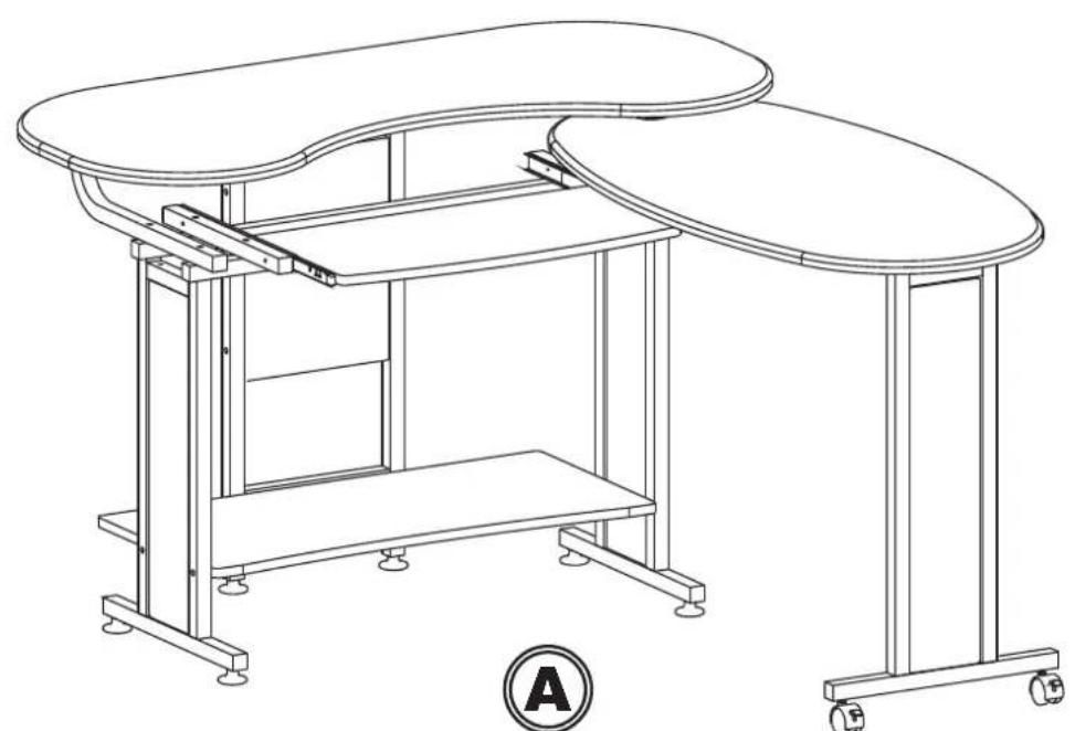
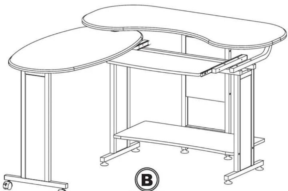
3 3 11** There are 2 options to assemble our desk, please choose it according to your preference.
natural_image
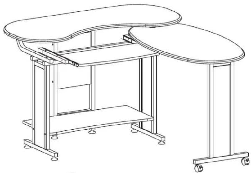
Line drawing of a modern office or workshop table setup with curved and flat panels, no text or symbols present.A1-A9
natural_image
Line drawing of a dual-plate office setup with curved top and horizontal base, no text or symbols presentB1-B9
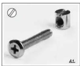
A1
text_image
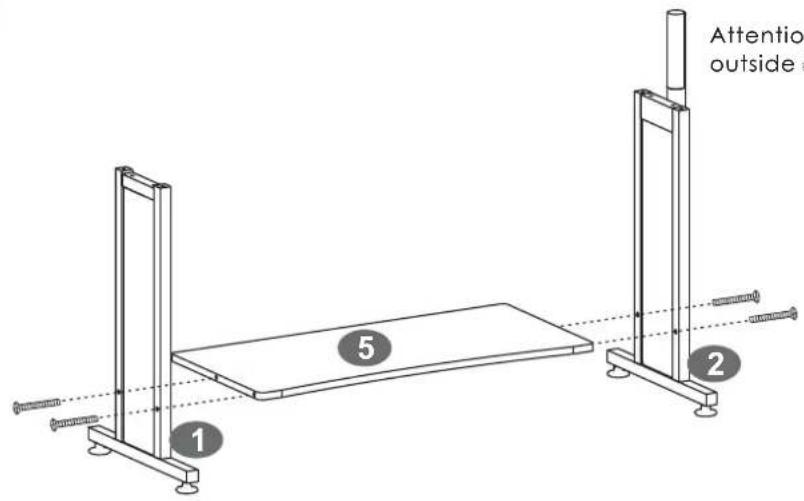
Attention outside 1 5 2Attention: The revolving tube must be outside of right leg.
■ SCREWS
A2
natural_image
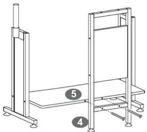
Technical line drawing of a mechanical assembly with two vertical supports and a horizontal shelf, labeled with numbers 4 and 5 (no text or symbols beyond labels)■SCREWS
A3
text_image
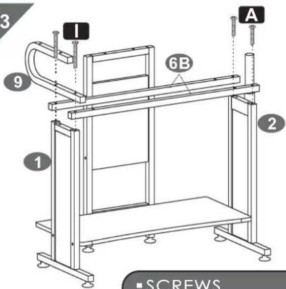
3 I 6B A 9 1 2 ■ SCREWSA4
text_image
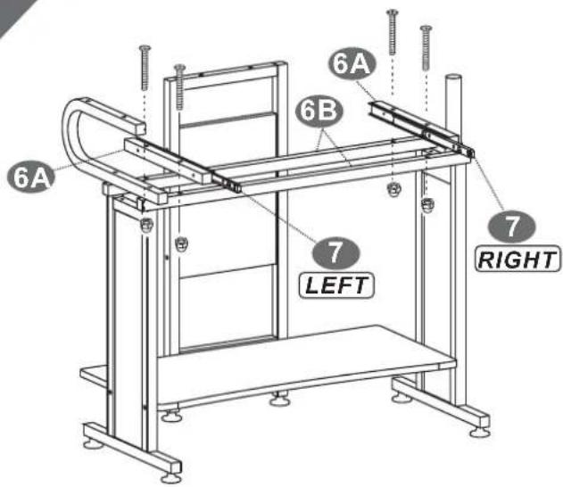
6A 6A 6B 7 LEFT 7 RIGHT■ SCREWS
■ SCREWS
A5
text_image
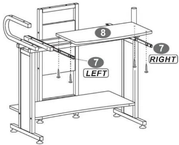
8 7 LEFT 7 RIGHT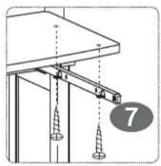
natural_image
Technical diagram showing a mechanical assembly with screws and a numbered circle (7), no readable text or symbols present.■SCREWS
E 4X14 MM
4PCS
A6
text_image
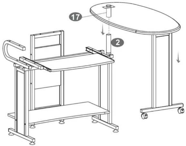
Technical diagram of a table setup with labeled components and directional arrows indicating assembly or movement.A7
text_image
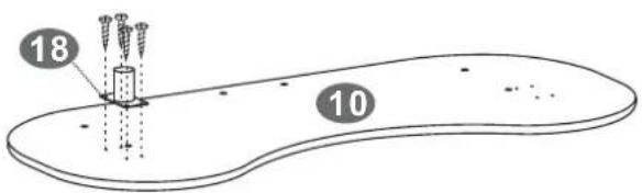
18 10■SCREWS
E 4X14 MM
4PCS
A8
text_image
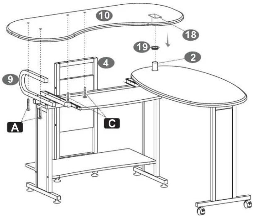
10 18 19 2 4 9 A C B■SCREWS
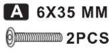
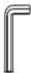
A 6X35 MM
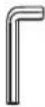
C 6X30 MM

A9
natural_image
Line drawing of a modern office or workshop table setup with curved top and horizontal shelves, no text or symbols present.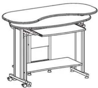
natural_image
Line drawing of a simple laboratory table with a curved top and horizontal supports (no text or symbols)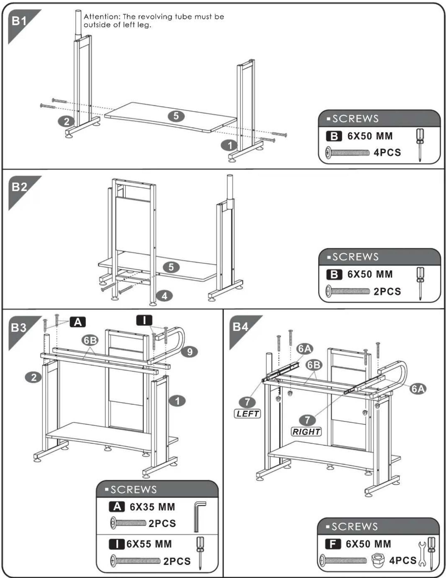
B5
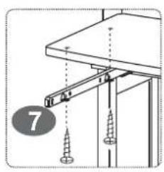
natural_image
Technical diagram showing a structural assembly with two screws and a base plate (no text or symbols)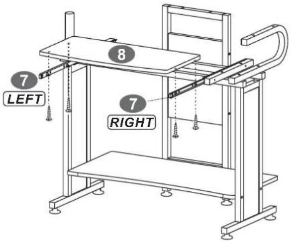
text_image
7 LEFT 8 7 RIGHT■SCREWS
E 4X14 MM
4PCS
B6
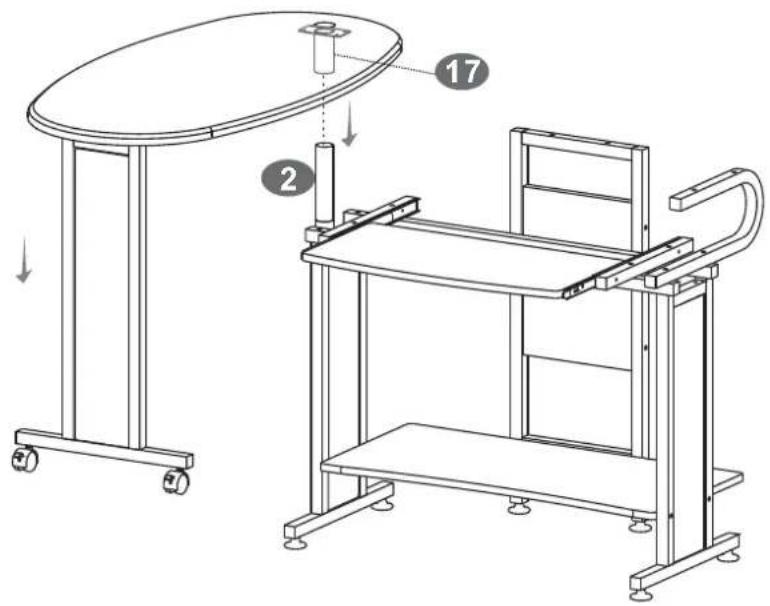
text_image
Technical diagram showing two views of a mechanical device with labeled components and directional arrows indicating assembly or assembly.B7
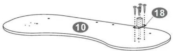
text_image
10 18■SCREWS
E 4X14 MM
4PCS
B8
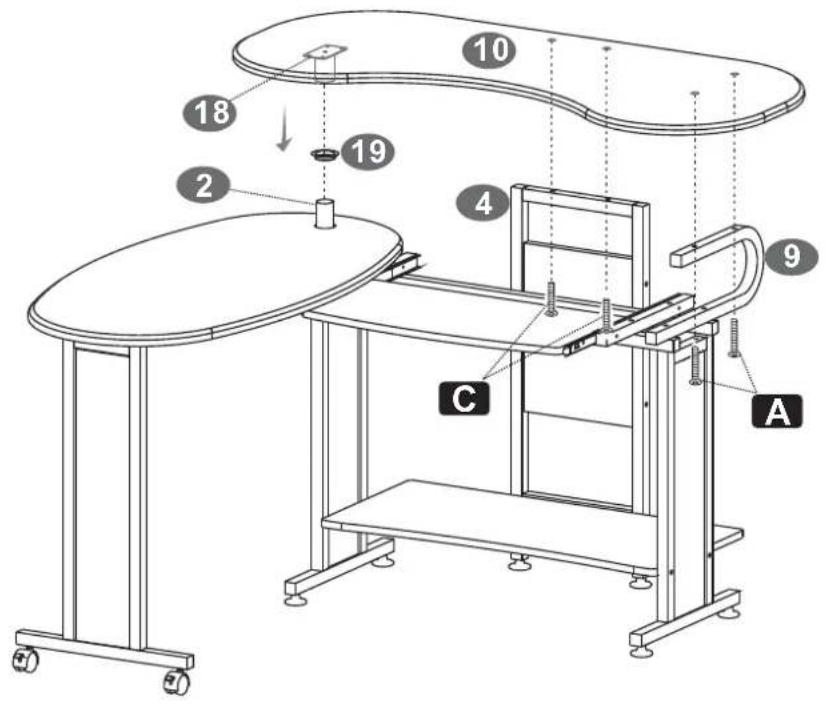
text_image
Technical diagram of a workbench with labeled components and numbered parts■ SCREWS
A 6X35 MM
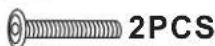
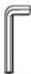
C 6X30 MM
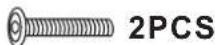
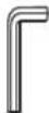
B9
natural_image
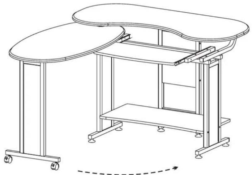
Technical line drawing of a dual-plate office setup with wheels and structural supports (no text or symbols)