WIQ1832EU - Waschmaschine SIEMENS - Kostenlose Bedienungsanleitung
Finden Sie kostenlos die Bedienungsanleitung des Geräts WIQ1832EU SIEMENS als PDF.


| Produkttyp | Waschmaschine |
| Marke | Siemens |
| Modell | WIQ1832EU |
| Bauart | Frontlader |
| Fassungsvermögen | 8 kg |
| Maximale Schleuderdrehzahl | 1200 U/min |
| Energieeffizienzklasse | A+++ |
| Schleuderklasse | B |
| Wasserverbrauch pro Jahr | ca. 9600 Liter |
| Stromverbrauch pro Jahr | ca. 176 kWh |
| Geräuschpegel Waschen | 51 dB |
| Geräuschpegel Schleudern | 76 dB |
| Höhe | 84,5 cm |
| Breite | 60 cm |
| Tiefe | 65 cm |
| Gewicht | ca. 75 kg |
| Anschlusswert | 2300 W |
| Netzspannung | 230 V |
| Frequenz | 50 Hz |
| Wasseranschluss | Kaltwasser |
| Besondere Merkmale | aquaStop, Schaumregulierung, Unwuchterkennung, Kindersicherung, Überlaufsicherung |
| Programme | Baumwolle, Pflegeleicht, Feinwäsche, Schleudern, Spülen, Schnellprogramm |
Häufig gestellte Fragen - WIQ1832EU SIEMENS
Benutzerfragen zu WIQ1832EU SIEMENS
0 Frage zu diesem Gerät. Beantworten Sie die, die Sie kennen, oder stellen Sie Ihre eigene.
Eine neue Frage zu diesem Gerät stellen
Laden Sie die Anleitung für Ihr Waschmaschine kostenlos im PDF-Format! Finden Sie Ihr Handbuch WIQ1832EU - SIEMENS und nehmen Sie Ihr elektronisches Gerät wieder in die Hand. Auf dieser Seite sind alle Dokumente veröffentlicht, die für die Verwendung Ihres Geräts notwendig sind. WIQ1832EU von der Marke SIEMENS.
BEDIENUNGSANLEITUNG WIQ1832EU SIEMENS
esInstruccionesdemontaje enInstallation instructions ptInstruçõesdemontagem
natural_image
Line drawing of a washing machine with control panel and suction tube (no text or symbols)Conexión
Elaparatosesuministralistoparalaconexiónalaredeléctrica y sólodeberáconectarseaunatomadecorrienteinstalada correctamenteyprovistadepuestaatierra.
Lainstalacióndeunatomadecorrienteolasustitucióndel cable deconexióndelaparatosólopodránserefectuadospor un electricista,deconformidadalasnormastécnicasválidas y aplicables.
Encasodenopoderalcanzarseelenchufetraselmontajedel aparato, lainstalación(red)eléctricadeberáestarequipadacon un dispositivodeseparacióndetodaslasfases, conunaapertura decontactomínimade3 mm.
Sólounmontajecorrectodeconformidadconlaspresentes instruccionesdemontajeaseguraunusocorrectodelaparato.
Losmueblesquenoestuvieransujetos,deberánfijarsealapared conunaescuadracorriente.
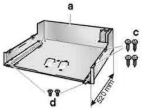
Volumendesuministro
Figura1
aChasis(concarrilestelescópicos)
bPlacadesoporteconaparatoyfrontal
c Tornillosparamadera(4 unidades)
dTornillosderoscacortante(2unidades)
Montajedelaparato
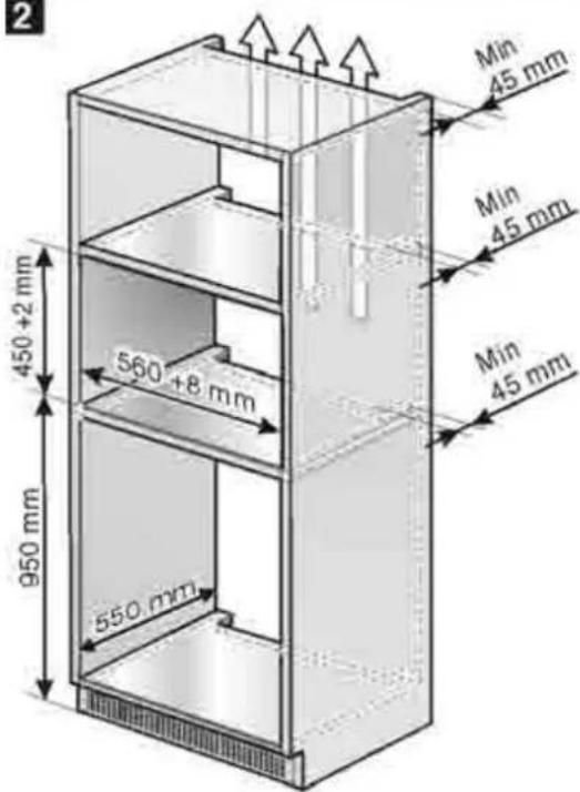
Figura2
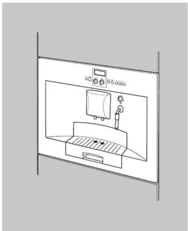
Elarmarioencastrablenodeberátenerdetrásdelosaparatos un panelposterior.
Entrelaparedyelfondodelarmariooelpanelposteriordel armariosituadoporencima, tienequeobservarseunadistancia mínimade 45 mm.
Lasrendijasdeventilaciónnylasaberturasdeaspiración no deberánestarnuncacubiertasnitapadasporobjetos.
Ténganseencuentaaesterespectotambiénlasinstrucciones de montajedelosaparatosemplazadosporencimaopordebajo delamáquina.
Encasodemontajeporencimadeuncajóncalientaplatos, el huecodemontajedeberátenerunaalturade 590 mm.
Encasodemontarelaparatodirectamentedebajodeunpanel decorativo, hayqueprestaratenciónaqueexistaunarendija de ventilacióndeporlomenos 200 cm ^2 .
Laalturademontajeidealparalacafeteraespressoes, medida desdeelsuelohastaelbordeinferiordelaparato, de95 cm.
- Desembalartodosloscomponentessegúnlasinstrucciones correspondientesyverificarsipresentandañosodesperfectos. Losaparatosquepresentarandañosodesperfectos no deberánponerseenmarcha.
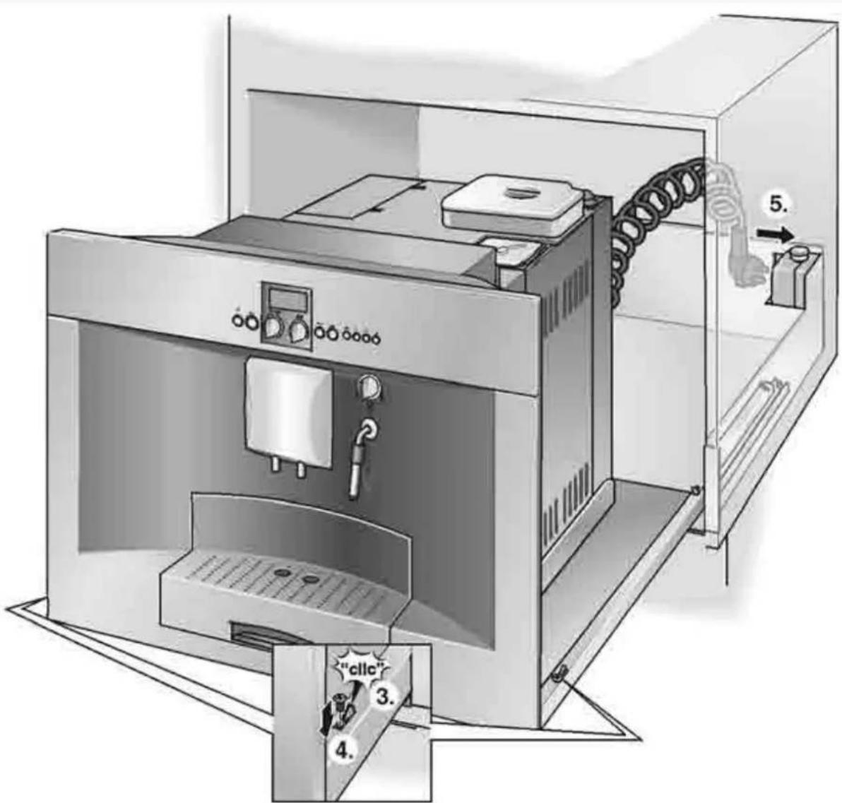
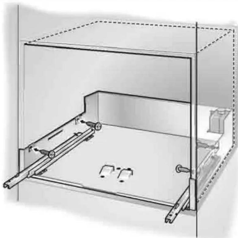
- Fijar el chasis a en posición central y con el frontal enrasado, con los 4 tornillos para madera c (Fig. 3).
- Introducirelcabledeconexióndelaparatoenlatoma de corriente. Elcabledeconexiónnodeberáestaraprisionadonipresentar dobleces.
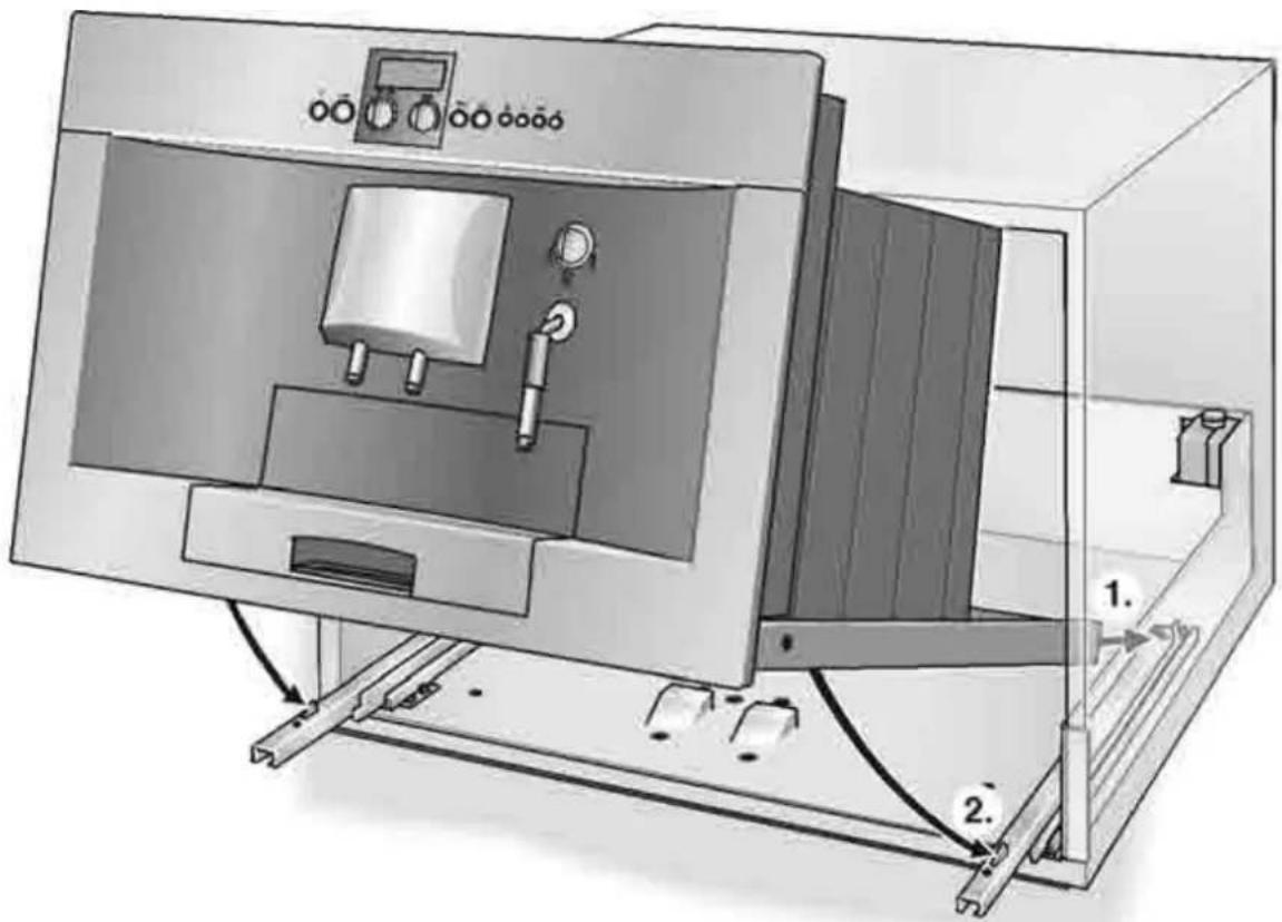
Figura4
- Desplegaramboscarrilestelescópicos.
- Montar la placa de soporte b con el aparato sobre los carriles telescópicos.
Fijarelaparatoconlosdostornillosd.
- Conectarelcableenespiraldelaparatoenelchasis.
Connection
The appliance is supplied with a fitted plug and maybe connected to accurately installed earthed socket only.
Onlyanelectricianmayfitasocketorreplacethepowercord in considerationoftherelevantregulations.
If the plug is no longer accessible following installation of the appliance, ther must bean all - poledis connector with a contact gap of least 3 mmonthe installations side.
Only an appliance which has been correctly installed according to these installation instructions can be used safely.
Attachloosefurnituretothewallwithaconventionalbracket.
Includedinstandarddelivery
Fig.1
aChassis(withtelescopicslides)
bSupportplatewithapplianceandfrontpanel
cWoodscrews(4x)
dSelf-tappingscrews(2x)
Installingtheappliance
Fig.2
The built-in unit must not have a rear panel behind the appliance. Theremust be agap of at least 45 mmb between the wall and base of the unit or there rear panel of the units situated above.
Theventilationslotsandintakeopeningsmustnotbecovered.
Also follow the installation instructions for the appliances situated above or below.
Ifinstallingtheapplianceaboveawarmingdrawer,theheight of therecessmustbe590mm.
If the appliance is installed directly under adécorpanel, ensure that there is a ventilation slot of at least 200 cm ^2 .
The ideal installation height for the fully automatic espresso machine, measured from the floor to the lower edge of the appliance, is 95cm.
- Firstunpackallpartsaccordingtotheinstructionsandcheck fordamageintransit. Donotswitchonadamagedappliance.
- Then attach the chassis a, centred and flush at the front, with the enclosed 4 screws c (Fig. 3).
- Insertthepowercordintothesocket. Donottraporkinkthepowercord.
Fig.4
• Pulloutbothtelescopicslides.
- Place the support plate b with the appliance on the two telescopic slides. Securewiththepre-assembledscrewsd.
- Insert the coiled cable of the appliance into the chassis.
Ligação
Oaparelhoestájápreparadoparaserligadoàcorrenteesópode serligadoaumatomadacomcontactodesegurança,instalada de acordocomasnormasemvigor.
Ainstalaçãodumatomadaouasubstituiçãoadocabode alimentaçõesópodeserexecutadaporumelectricistacredenciado e respeitandoasnormasemvigor.
Seaficha, depoisdainstalaçãodoaparelho, deixardeestar acessível, temqueexistirnainstalaçãoumdispositivodecorte multipolarcomumaaberturadecontactosde, pelomenos, 3 mm.
Sóumamontagemcorrecta, respeitandoestasinstruções de montagem, garanteuma utilização com segurança.
Osmóveissoltosdevemserfixadosàparedecomumapeça em ângulo,correntenomercado.
Amplitudedofornecimento
Fig.1
aChassis(comextensõestelescópicas)
bPlacadesuportecomaparelhoefrente
cParafusosdemadeira(4unidades)
dParafusosauto-atarraxadores(2unidades)
Montagemdoaparelho
Fig.2
Oarmárioparamontagem, portrásdosaparelhos, não pode possuirumaparedeposterior. Entreaparedeeabasedoarmárioouaparedeposterior do armáriolocalizadoporcimatemqueexistirumadistância mínimade 45 mm.
Asranhurasdeventilaçãoeasaberturasdeaspiraçãoonãopodem sertapadas.
Paraisso, respeitar, também, asinstruções demontagem do aparelho, localizador porcima ouporbaixo.
Emcasodemontagemporcimadumagavetadecalor é necessárioumnichode 590 mm.
Seoaparelhoforinstaladodirectamenteporbaixodumaplaca decorativa,deveter-seematençãoquetemqueexistiruma ranhuradeventilaçãode 200 cm ^2 .
Aalturademontagemidealparaamáquinadecaféexpresso totalmenteautomática,medidadochãoatéaarestainferior do aparelho,éde95 cm.
- Primeiro, desembalaroscomponenteseverificar, seexistem danoscausadosospelotransporte.
Osaparelhosqueapresentemdanosnãopodemserpostos emfuncionamento.
- Fixarochassisacentradoalinhadoàfacecom os 4 parafusos c (Fig. 3).
- Ligarocabodealimentação à tomada. Ocabonãopodeficarentaladonemdobrado.
Fig.4
•Puxarasduasextensõestelescópicasparafora.
- Assentar a placa de suporte b com o aparelho sobre as duas extensõestelescópicas.
Fixarcomosparafusosdpré-montados.
- Introduzirocaboemespiraldoaparelhonochassis.
1
text_image
a c d 520 mm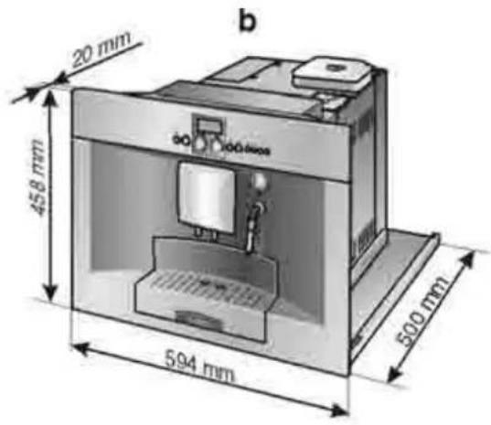
text_image
20 mm 458 mm 594 mm 500 mm b2
text_image
2 450 + 2 mm 950 mm 560 + 8 mm 550 mm Min 45 mm Min 45 mm Min 45 mm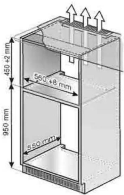
text_image
450 +2 mm 560 +8 mm 950 mm 550 mm
text_image
560 +8 mm 590 +2 mm 550 mm3
natural_image
Technical line drawing of a mechanical assembly with no visible text or symbols4
text_image
Technical diagram of a laboratory instrument with labeled parts and directional arrows indicating assembly or movement.