
HB86P672B - Ofen SIEMENS - Kostenlose Bedienungsanleitung
Finden Sie kostenlos die Bedienungsanleitung des Geräts HB86P672B SIEMENS als PDF.


Benutzerfragen zu HB86P672B SIEMENS
0 Frage zu diesem Gerät. Beantworten Sie die, die Sie kennen, oder stellen Sie Ihre eigene.
Eine neue Frage zu diesem Gerät stellen
Laden Sie die Anleitung für Ihr Ofen kostenlos im PDF-Format! Finden Sie Ihr Handbuch HB86P672B - SIEMENS und nehmen Sie Ihr elektronisches Gerät wieder in die Hand. Auf dieser Seite sind alle Dokumente veröffentlicht, die für die Verwendung Ihres Geräts notwendig sind. HB86P672B von der Marke SIEMENS.
BEDIENUNGSANLEITUNG HB86P672B SIEMENS
1
text_image
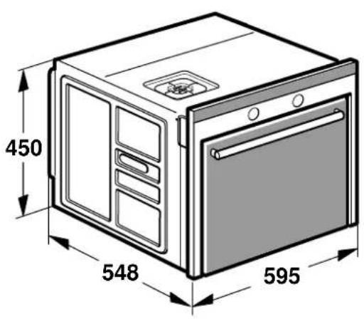
450 548 595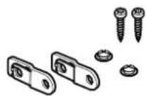
text_image
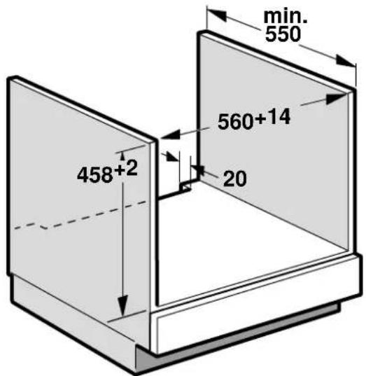
min. 550 560+14 20 458+2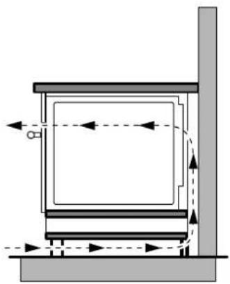
natural_image
Pure technical diagram of a mechanical assembly with no text, numbers, or symbols2

text_image
600 560+14 min 550 450+2 45 45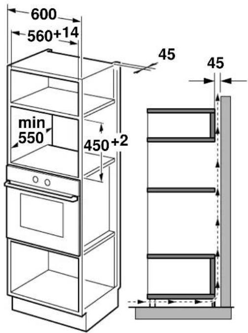
text_image
600 560+14 min 550 450+2 45 453
text_image
E min. 90D
text_image
min. 454
text_image
max. 16 18-20 15-17 click max. 16 max. 16 13-145
text_image
min. 5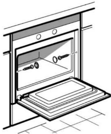
natural_image
Line drawing of an oven with a tray and two outlets, no text or symbols presenten
The following must be noted:
Electrical connection
The appliance is fitted with a plug and must only be connected to a properly installed earthed socket. Only a qualified electrician who takes the appropriate regulations into account may install the socket or replace the connecting cable.
If the plug is no longer accessible following installation, an all-pole isolating switch must be present on the installation side with a contact gap of at least 3 mm.
Contact protection must be ensured by the installation.
United Kingdom and Australia
The appliance is designed for a permanent connection to a 3-wire circuit. The appliance must only be connected by a qualified electrician in accordance with the wiring diagram attached to the connecting cable.
An all-pole disconnecting device must be present on the installation side with a contact gap of at least 3 mm in order to comply with current safety regulations.
The appliance fulfils the requirements of protection class Y, in accordance with heating test standards. The colours of the wires in the mains cable correspond to the following coding: green/yellow = PE conductor, blue = neutral conductor, brown = phase. Do not connect the appliance using a 13 A plug or protect with a 13 A fuse.
Fitted units
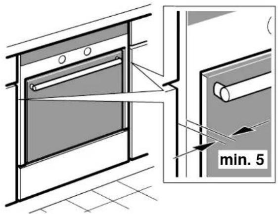
The fitted cabinet must not have a back wall behind the appliance. A gap of at least 45 mm must be maintained between the wall and the cabinet base and/or the back panel of the overlying cabinet.
The fitted cabinet must have a ventilation opening of 50 cm^2 on the front. For surround units with no ventilation cut-out in the back of the side panels 200 cm^2 . To do this, cut back the base panel or fit a ventilation grille.
Make sure that you do not cover ventilation slots and air inlet openings.
The safe operation of this appliance can only be guaranteed if it has been installed to a professional standard in accordance with these installation instructions. The installer is liable for damage incurred as a result of incorrect installation.
Fitted units must be heat-resistant up to 90 °C, and neighbouring unit fronts up to at least 70 °C.
Cut-out work on the units and worktop should be performed before fitting the appliances. Remove any shavings or the function of the electrical components may be impaired.
Appliance under the worktop - Fig. 1
There must be a ventilation cut-out made in the intermediate floor of the surround unit.
Secure the worktop to the fitted units.
If a fitted oven is to be built in under a hob, pay attention to the hob installation instructions.
Appliance in a tall unit - Fig. 2
The appliance may only be fitted above a ventilated oven from the same manufacturer.
Installation above a refrigerator is possible.
The appliance must not be fitted above a steamer, combination steam oven or a dishwasher.
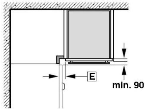
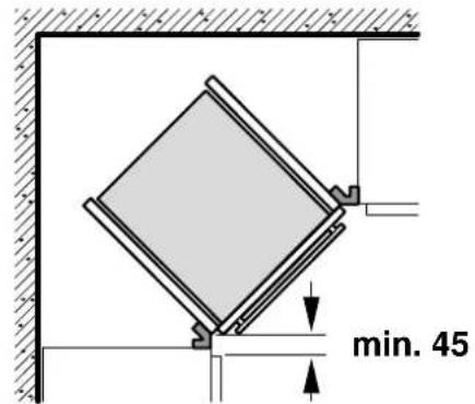
Corner installation - Fig. 3
For corner installation, dimension D must be taken into consideration. Dimension E is dependent on the thickness of the unit front and the handle.
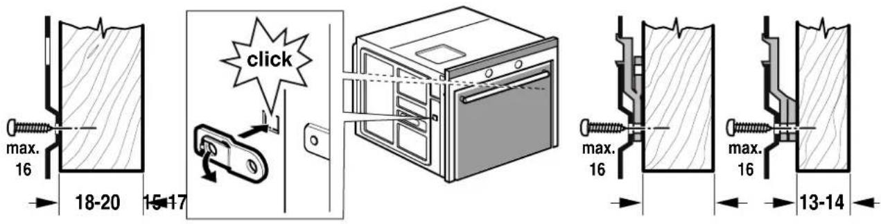
Preparing for installation - Figs 4
If necessary, fit the spacer - Fig. 4.
Securing the appliance - Fig. 5
■ Fully insert the appliance and centre it.
■ Do not kink the connecting cable.
■ Screw the appliance into place.
■ The gap between the worktop and the appliance must not be closed by additional battens.
Removal
Disconnect the appliance from the power supply. Undo the securing screws. Raise the appliance slightly and pull it out completely.