Flush PWM - Thermostat Qubino - Kostenlose Bedienungsanleitung
Finden Sie kostenlos die Bedienungsanleitung des Geräts Flush PWM Qubino als PDF.


Benutzerfragen zu Flush PWM Qubino
0 Frage zu diesem Gerät. Beantworten Sie die, die Sie kennen, oder stellen Sie Ihre eigene.
Eine neue Frage zu diesem Gerät stellen
Laden Sie die Anleitung für Ihr Thermostat kostenlos im PDF-Format! Finden Sie Ihr Handbuch Flush PWM - Qubino und nehmen Sie Ihr elektronisches Gerät wieder in die Hand. Auf dieser Seite sind alle Dokumente veröffentlicht, die für die Verwendung Ihres Geräts notwendig sind. Flush PWM von der Marke Qubino.
BEDIENUNGSANLEITUNG Flush PWM Qubino
Qubino

The INNOVATIVE and SMALLEST
Flush PWM Thermostat
| ORDERING CODE | Z-WAVE FREQUENCY |
| ZMNHLD1 | 868.4 MHz |
| ZMNHLD2 | 921.4 MHz |
| ZMNHLD3 | 908.4 MHz |
| ZMNHLD4 | 869.0 MHz |
| ZMNHLD5 | 916.0 MHz |
| ZMNHLD6 | 865.2 MHz |
This Z-Wave module is used to regulate temperature. Regulation is done using full wave PWM technology. The module can be controlled either through Z-wave network or through the wall switch.
The module is designed to be mounted inside a "flush mounting box" and is hidden behind a traditional wall switch. Module measures power consumption of connected device. It is designed to act as repeater in order to improve range and stability of Z wave network.
Supported switches
Module supports mono-stable switches (push button) and bi-stable switches. The module is factory set to operate with bi-stable switches.
Installation
- To prevent electrical shock and/or equipment damage, disconnect electrical power at the main fuse or circuit breaker before installation or any servicing.
- Make sure, that no voltage is present in the installation - Prevent the disconnecting device from being switched on accidentally.
- Connect the module according to electrical diagram. - Locale the antenna far from metal elements (as far as possible).
• Do not shorten the antenna.
Danger of electrocution! - Module installation requires a great degree of skill and may be performed only by a qualified and licensed electrician.
- Even when the module is turned off, voltage may be present on its terminals. Any works on configuration changes related to connection mode or load must be always performed by disconnected power supply (disable the fuse).
Note!
Do not connect the module to loads exceeding recommended values. Connect the module only in accordance to the below diagrams. Improper connections may be dangerous.
Electrical installation must be protected by directly associated over current protection fuse 1A, gG or Time lag T, rated breaking capacity 1500A (ESKA 522.717) must be used according to wiring diagram to achieve appropriate overload protection of the module. The fuse must be installed in fuse holder type: Adels contact 503 Si / 1 DS
Package contents:
- Flush PWM thermostat + Temperature sensor
Electrical diagram 230VAC
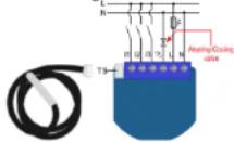
Notes for the diagram:
N Neutral load
L Live lead
Output
13 Input for switch /push button or sensor* 12 Input for switch /push button or sensor* 11 Input for switch /push button or sensor* TS Terminal for digital temperature sensor (only for Flush PWM thermostat module compatible digital temperature sensor).
*For details please check parameters 11, 12 and 13 Electrical diagram 24VDC
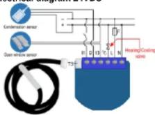
Notes for the diagram:
N + VDO
L - VDC
Output
10
I3 Input for switch /push button or sensor* I2 Input for switch /push button or sensor* I1 Input for switch /push button or sensor* TS Terminal for digital temperature sensor (only for Flush PWM thermostat module compatible digital temperature sensor).
*For details please check parameters 11, 12 and 13 \$ Service button (used to add or remove module from the Z-Wave network in case of 24 V SELV power supply).
WARNING: Service button S must NOT be used when module is connected to 110-230V power supply. WARNING: the temperature sensors should not be exposed to water. Module Inclusion (Adding to Z-wave network)
- Connect module to power supply (with
temperature sensor connected),
- enable add/remove mode on main controller - auto-inclusion (works for about 5 seconds after connected to power supply) or
- press push button 11 three times within 3s (3 times change switch state within 3 seconds) or - press service button 5 (only applicable for 24 V SELV supply voltage) for more than 2 second.
NOTE 1: For auto-inclusion procedure, first set main controller into inclusion mode and then connect module to power supply.
NOTE 2: When connecting temperature sensor to module that has already been included, you have to exclude module first. Switch off power supply, connect the sensor and re-include the module.
Module Exclusion/Reset (Removing from wireless network)
- Connect module to power supply
- bring module within maximum 1 meter (3 feet) of the main controller,
- enable add/remove mode on main controller - press push button 11 live times within 3s (5 times change switch state within 3 seconds) in the first 60 seconds after the module is connected to the power supply or
- press service button S (only applicable for 24 V SELV supply voltage) for more than 6 second.
By this function all parameters of the module are set to default values and own ID is deleted.
If push button II is pressed three times within 3s (or service button S is pressed more than 2 and less than 6 seconds) module is excluded, but configuration parameters are no set to default values.
NOTE: If the module is included with parameters 100,101 or 102 with values different to default and module reset is done, wait at least 30s before next inclusion.
Association
Association enables PWM thermostat module to transfer commands inside Z-Wave network directly (without main controller) to other Z-Wave modules.
Associated Groups:
Group 1: Lifeline group (reserved for communication with the main controller), 1 node allowed.
Group 2: basic on/off (triggered at change of the output Q state and reflecting its state) up to 16 nodes.
Group 3: SENSOR_MULTILEVEL_GET (triggered once per minute if Parameter 121 is not 0) up to 16 nodes.
Group 4: basic on/off (triggered by Too high temperature limit, it send 0x00 in Heating mode and 0xFF in Cooling mode, triggered by Too low temperature limit, it send 0x00 in Heating mode and 0xFF in Cooling mode; hysteresis is 1°C) up to 16 pads.
Group 5: THERMOSTAT_SETPOINT_GET (triggered once per minute if Parameter 121 is not 0) up to 16 nodes. Group 6: basic on/off (trigged by change of 11 if window sensor functionality is selected by parameter no. 11) up to 16 nodes.
Group 7: basic on/off (trigged by change of 12 if condense sensor functionality is selected by parameter no. 12) up to 16 nodes.
Group 8: basic on/off (trigged by change of 13 if flood sensor functionality is selected by parameter no. 13) up to 16 nodes.
Group 9: sensor multilevel report (trigged by change of temperature) up to 16 nodes.
Group 10: Basic on/off (triggered by change of the output Q plate and reflecting its plate, up to 15 nodes
state and reflecting its state, up to 16 nodes. Basic Set ON command is delayed for the time defined in parameter no. 77.
Basic Set OFF command is reported immediately.
Configuration parameters
Parameter no. 1 - Input I1 switch type
Available config. parameters (data type is 1 Byte DEC)
- default value 1
- 0 - mono-stable switch type (push button)
• 1 - bi-stable switch type
Parameter no. 2 - Input I2 switch type
See parameter 1 (valid for I2 instead of II)
Parameter no. 3 - Input I3 switch type
See parameter 1 (valid for 13 instead of 11) Parameter no. 4. Input 1 contact type
Parameter No. 4 - Input 1 contact type Available config parameters (data bits is 1 Byte DEC):
• default value 0
• 0 - NO (normally open) input type
• 1 - NC (normally close) input type
NOTE: This parameter has influence only when parameter no. 11 is set to the value "2". After selling this parameter switch the window sensor once, so that the module could determine the input state.
Parameter no. 5 - Input 2 contact type
See parameter 4 (valid for I2 instead of I1)
NOTE: This parameter has influence only when parameter
no. 12 is set to the value "2000". After setting this parameter, switch the condense sensor once, so that the module could determine the input state.
Parameter no. 6 - Input 3 contact type
See parameter 4 (valid for I3 instead of II) NOTE: This parameter has influence only when parameter
NOTE: This parameter has imborise only when parameter no. 13 is set to the value "2". After setting this parameter,
switch the flood sensor once, so that the module could determine the input state.
Parameter no. 10 - Activate / deactivate functions ALL ON/ALL OFF
Available config. parameters (data type is 2 Byte DEG):
- default value 255
• 255 - ALL ON active, ALL OFF active.
- 0 - ALL ON is not active ALL OFF is not active
• 1 - ALL ON is not active ALL OFF
• 2 - ALL ON active ALL OFF is not active
Flush PWM thermostat module responds to commands ALL ON / ALL OFF that may be sent by the main controller or by other controller belonging to the system.
Parameter no. 11-11 Functionality selection Available config. parameters (data type is 2 Byte DEC): • default value 1
• 32767 - Input I1 doesn't influence on the Heat/Cool process
- 1 - input I changes the mode of the thermostat between Off and Heat/Cool. In this case function on window sensor is disabled
• 2 - input I1 influences on healing/cooling valves
according to status of window sensor. In this case function of Off and Heat/Cool selection by 11 is disabled.
NOTE: If "Window Sensor" selected (value set to *2'), parameter 100 (enable/disable endpoint) must be set to non zero value and module re-included!
Parameter no. 12 - I2 Functionality selection
Available config. parameters (data type is 2 Byte DEC); - default value 32767
• 32767 - input l2 does not influence on the Heat/Cool process
- From 0 to 990 - Temperature set point from 0.0 °C to 99.0 °C. When I2 is pressed, it automatically set temperature setpoint according to value defined here. In this case function of condense sensor is disabled
- From 1001 to 1150 - Temperature set point from -0.1 °C to -15.0 °C. When I2 is pressed, it automatically set temperature setpoint according to value defined here. In this case function of condense sensor is disabled
• 2000 - Input I2 influences on the cooling valve
according to status of condense sensor, In this case function of apostin selection with _1 is disabled.
function of 56point selection with H2 is disabled NOTE: If "Condense Sensor" selected (value set to "2000"), parameter 101 (enable/disable endpoint) must be set to non zero value and module re-included!
Parameter no. 13 - I3 Functionality selection
Available config. parameters (data type is 2 Byte DEC):
- default value 32767
• 32767 - input I3 does not influence on the heat/cool
process
- 1 - input I3 changes the mode of the thermostat between Heat and Cool and overticle parameter 59. In this case function on flood sensor is disabled NOTE: After parameter change, first exclude module (without setting parameters to default value) and then re include the module!
- 2 - input I3 influences on heating/cooling valves according to status of flood sensor. In this case function Heat/Cool selection by I3 is disabled
NOTE1: If this parameter is changed, it is necessary to re-include the module.
NOTE2: II "Flood Sensor" selected (value set to "2"), parameter 102 (enable/disable endpoint) must be set to non zero value and module re-included!
Parameter no. 40 - Power reporting in Watts on power change
Set value means percentage, set value from 0 - 100 = 0% - 100%. Available configuration parameters (data type is 1 Byte DEC):
• default value D
• 0 - reporting disabled
- 1-100 - 1%-100% Reporting enabled. Power report is send (push) only when actual power in Watts in real time changes for more than set percentage comparing to previous actual power in Watts, step is 1%.
NOTE: If power changed is less than 1W, the report is not send (pushed), independent of percentage set.
Parameter no. 42 - Power reporting in Watts by time interval
Set value means time interval (0 - 32767) in seconds, when power report is send. Available config. parameters (data type is 2 Byte DEC):
• default value 0 (power report is disabled)
• 0 - reporting disabled
- 1 - 32767 - 1 second - 32767 seconds. Reporting enabled. Power report is send with time interval set by entered value.
Parameter no. 45 - Antifreeze
Set value means at which temperature the device will be turned on even if the thermostat was manually set to off. Available config. parameters (data type is 2 Byte DEC):
• default value 50 (5,0 °C)
- 0 - 127 = 0,0°C ... 12.7 °C
• 1001 - 1127 = -0,1°C ... - 12,6 °C
• 255 - Antifreeze functionality disabled
NOTE: Antilfreeze is activated only in heating mode.
Parameter no. 50 - PWM maximum value
Available config. parameters (data type is 1 Byte DEC):
• default value 100 (Maximum PWM value)
- 2-100 - 2%-100%. step is 1%. Maximum PWM set by
entered value
NOTE: The maximum level may not be lower than the
minimum level!
Parameter no. 51 - PWM minimum value
Available config. parameters (data type is 1 Byte DEC):
- Default value 0 (Minimum dimming value is 0%)
- 1-99 = 1% - 99%, stop is 1%. Minimum PWM set by
entered value
NOTE: The minimum level may not exceed max. level
Parameter no. 52 - PWM cycle duration
Available config. parameters (data type is 1 Byte DEC)
- default value 10 (Minimum dimming value is 0%)
- 5 - 127 - 1 - 127s, step is 1s. PWM cycle duration set by entered value.
NOTE: PWM cycle duration define the summary of all ON plus OFF time periods. For example if Output is set to 70% with PWM cycle duration of 20s, output will be ON for 14s then OFF -6s, again 14s ON, etc...
Parameter no. 53 - PID value inside deadband
Available config. parameters (data type is 1 Byte DEC): - default value 0 (PID value equal PWM minimum value)
• 1 - PID value set to LAST VALUE
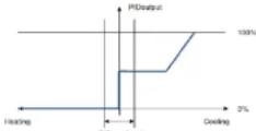
NOTE: When value is set to "0", PID inside deadband is forced to PWM minimum value. LASTVALUE means that PID remains on same level as was before entering into deadband.
Parameter no. 54 - PID deadband
Available config. parameters (data type is 1 Byte DEC):
• default value 5 (0.5 °C)
- 0-127 - 0.0 °C to 12.7 °C, step is 0.1°C
NOTE: This parameter defines the zone where PID is not active. If the temperature difference between actual and setpoint is bigger than PID deadband, then the PID will start to regulate the system, otherwise the PID is zero or fixed.
Parameter no. 55 - Integral sampling time
Available config. parameters (data type is 1 Byte DEC):
- default value 5 (5s)
• 0-127 - 0s to 127s, step is 1s
Parameter defines the time between samples. On each sample the controller capture difference between SP-act.
Parameter no. 56 - P parameter
Available config. parameters (data type is 2 Byte DEC):
- default value 100
- 0 -1000 - P value, stop is 1
Parameter no. 57 - I parameter
Available config. parameters (data type is 2 Byte DEC):
- default value 1
• 0 - 1000 - I value, step is 1
Parameter no. 58 - D parameter
Available config. parameters (data type is2 Byte DEC):
- riafruit value 1
- 0,1000. D value step in
Drosophila no. 50. Therapical mode
Available cardin parameters (data type in 1 Data DEC)
Available Corning
- scratch value of
• 0 - Heat mode
• 1 - Cool mode
If parameter changed it is necessary to re-include module.
Parameter no. 60 - Too low temperature limit
Available configuration parameters (data type is 2 Byte
DECY
- Default value 50 (Too low temperature limit is 5.0°C)
- 1700 = 0.1^ to 10^n ^6C , step is 0.1^
1706-6157:3487to-1579
- 1501...+159.4.1 C to -15.3 C
Too low temperature limit is used with Association Group 4
Parameter no. 61 - Too high temperature limit
Available config. parameters (data type is 2 Byte DEC)
- default value 700 (top high temperature limit is
70.0°C
- 1000 = 0.1°C - 100.0°C, ring is 0.1°C. Too high
temperature limit is used with Association Group 4.
Parameter no. 52 Output Switch selection
Parameter not so - Output Option Selection Sed value means the type of the device (that) is supported by
GB: Valid means the type of the device that is connected to the PMI-104.
the 1-WMI output. The device type can be normally open
(NO) or normally close [NO]
Available conlip. parameters (data type is 1 Byte DEC)
- default value 0
- 0 - When system is turned off the output is 0 V
- When system is turned off the output in 000 V
- When system is limited on the output
Parameter No. 70 - Input 1 status on delay
Available coming. parameters (data type is 2 Byte DEC).
• default value 0
• 1 - 32000 seconds
If the value of parameter is different to 0, means that the
Influence of this input to heating or cooling will react after
improved lime. This is a example that influences only when the
with the following described property is selected by Theorem 68.
Mitsow Samb: functionality is selected by the paralnatal no
11.
NOTE: Device status on of change immediate
Parameter no. 71 - Input 1 status off delay
Available config. parameters (data type is 2 Byte DEC)
- default value 0
• 1 - 32000 seconds
If the value of parameters is different to 7, means that lie
In favor of this input to heating or cooling will soon after
Influence of this input to heating or cooling will react after
inserted time. This parameter has influence only when the
Window sensor functionality is selected by the parameter no
11.
NOTE: Device status on UI change immediately
Parameter no. 72 - Input 2 status on delay
See parameter 70 (valid for 12 instead of 11)
This parameter has influence only when the condense
sensor functionality is selected by the parameter no. 12
Parameter no. 73 - Input 2 status off delay
See numerator 71 Avoid for (2 instead of 11)
Use parameter 71 (valid for 12 instuts of 11,
This parameter has influence only when the consensus
sensor functionality is selected by the parameter no. 12.
Parameter no. 74 - Input 3 status on delay
See parameter 70 (valid for is instead of 11)
This parameter has influence only when the flood sensor
functionality is selected by the parameter no. 13.
Parameter no. 75 - Input 3 status off delay
See parameter 71 (valid for I3 instead of I1)
This parameter has influence only when the flood seno
functionality is related by the parameter no. 13
Parameters no. 76. Association group 0, 49, reporting
Paramotor No. 1
on time interval
Available config. parameters (data type is + Byte DEG)
• Default value 30 = 30 minutes
• D - Reporting disabled
• 1-127 - 1 minute - 127 minutes reporting enabled
NOTE: If the Association groups 2 or 10 are set, the device
is reporting its state (Revis Sat CW CEE) on change and an
to reporting its claims (with set off, set off) on change and on time interval (if this parameter is set).
unio interwai în this paralictor is sec.
Parameter no. 77 - Association group 10 - delay before
sending Basic Set ON/OFF
Available config. parameters (data type is 2 Byte DEC):
• Default value 180 - 3 minutes
-
-
-
-
-
-
-
-
-
-
-
-
-
-
-
-
-
-
-
-
-
-
-
-
-
-
-
-
-
-
-
-
-
-
-
-
-
-
-
-
-
-
-
-
-
-
-
-
-
-
-
-
-
-
-
-
-
-
-
-
-
-
-
-
-
-
-
-
-
-
-
-
-
-
-
-
-
-
-
-
-
-
-
-
-
-
-
-
-
- 99.
-
-
-
-
-
-
-
-
-
-
-
-
-
-
-
-
-
-
-
-
-
-
-
-
-
-
-
-
-
-
-
-
-
-
-
-
-
-
-
-
-
-
-
-
-
-
-
-
-
-
-
-
-
-
-
-
-
-
-
-
-
-
-
-
-
-
-
-
-
-
-
-
-
-
-
-
-
-
-
-
-
-
-
-
-
-
-
-
• 0 = Нерань WITH NO DELAY
• 1-327
enabled
NOTE: If this parameter is set, Basic Set ON/OFF Report is
delayed for the time defined in this parameter.
Parameter no. 78 - Scale Selection
Available config parameters (date type is 1 Byte DECI)
- Default value - degree Correct
• British value c = 05
• 0 = degree Celsius
• 1 = degrees Fanichnell
NOTE: This scale has influence on Temperature reporting
and scale reporting. The device
Setpoint in all supported scales
Parameter no. 100 - Enable / Disable Endpoint I1 or
select Notification Type and Event
Enabling II means that Endpoint (I1) will be present on III
endusing IT module that Endpoint (IT) will be precontrol on CI. Disabling it will result in hiding the endpoint according to the
Explaining it will result in hiding the captain according to in parameters and values. Additionally, a Modification Turn need
Event can be selected for the endpoint. Available
Even can be selected for the endpoint. Available
configuration parameters (data type is 1 Byte DEC).
Endpoint device type selection
- notification sensor (1 - 6):
GENERIC TYPE SENSOR NOTIFICATION,
SPECIFIC TYPE NOTIFICATION SENSOR
default value 0
-
Home Security Motion Detection unknown location
-
CO: Carbon Monoxide detected, unknown location
-
CO2 Carbon Nanoparticles detected unknown location
-
Water Alarm: Water Look detected, unknown location.
-
Unit Name: Overcoat detected, unknown location
3 - Float Altern, Chemical detected, Enrichment location
- Smoke Alarm, Smoke detected, Unknown location
0 - Endpoint, IT dissected
- sensor binary (9): GENERIC_TYPE_SENSOR_BINARY
SPECIFIC TYPE NOT USED
9 - Sensor binary
NOTE1: After parameter changes, first exclude module
(without setting parameters to default value) and then re
(1) Using the module for a module with two sets of modules, including the module.
NOTE 2: When the parameter is set to value 9 the
sellatories are good for Home Security.
nottodations are bonds for Home Security
NOTES: If endpoint enabled (value set to 1..9), parameter
11 must be set to "2" as "Window Sensor"
Parameter no. 101 - Enable / Disable Endpoint I2 or
select Notification Type and Event
See parameter 100 (valid for |2 instead of |1)
NOTE: If "endpoint enabled" /value set to 1, 91 parameter
12 must be set in "3000" or "Canderson Sensor"
Pavamatsu no. 489. Enable / Disable Endpoint IP av
Parameter No. 102 = Enable / Disable Endpoint 13 of select Notification Type and Event
One representative 100 (valid for ID instead of ID)
a. public matter: No (vend ka ka malaka di)
NOTE: If endpoint enabled (value set is 1..9), parameter
13 must be set to 2 as Flood Sensor
Parameter no. 110 - Temperature sensor offset settings
Set value result in adding or subtracting that value to actual
measured value by sensor.
Available config. parameters (data type is 2 Byte DEC):
• default value 325
- 20598 effect in
- 0256 - 0120118 013
- From 1 to 100 = value from 0.1 °C to 10.0 °C is added
to actual measured temperature.
• From 1001 to 1100 - value from -0.1 °C to -10.0 °C is
subtracted to actual measured temperature
Parameter no. 120 - Digital temperature sensor
reporting
If digital temperature sensor is connected, module reports
measured temperature on temperature change defined by
this parameter
Available profile parameters (data type is 1 Rate DEC)
Available boring parameters (delta type is 1 Byte BEO);
- 陈雪峰 张晓
• U - Reporting disabled
- 1-127 = 0.1°C - 12.7°C, step is 0.1°C
Parameter no. 121 - Digital temperature sensor
setpoint selector
If digital temperature sensor is not connected, module can
grab measured temperature from external secondary
module. Available, a pin, parameters (into two in 1 Dax
DECI:
DEO:
• default value c
- 0 - internal digital temperature sensor is mounted.
setpoint is set by controller
• 1 - (bit) 5) temperature in grabbed from external
always an sensor with sensor must level out sent by
ansprisiting 2
• The following table provides the information and the content of
• 2 - (bit 1) temperature is grasoded from external
battery powered room sensor declared in parameter 122
• 4 - (bit 2) setpoint is grabbed from external always on
module with thermostat_setpoint_get sent by association 5
• 8 - (blt 3) setpoint is grabbed from external battery
powered room sensor declared in parameter 122
• 10 - (bit 1 and bit 3) temperature AND angle point am
- 10 - (min) 3.4 mm by comparators and 60 ppm and archived from capacitor battery powered room sensor
graduated from external battery powered to school
declared in parameter 122
Parameter No. 122 - Node ID of external battery
powered room sensor
If digital temperature sensor is not connected, module can
grain measured temperature from external battery powered
room sensor defined by this parameter
Available config. parameters (data type is 1 Byte DEC)
- default value 2
- external rubber, several mm pressure rel in
- 0 = external battery powered toon sensor not in
function
• 1-254 = Node ID of external battery powered room
SENSOR
NOTE: Gel sensor node id from controller and sel
parameter 122 immediately after sensor weak up (after
button press go it etc.)
Functionality
Functionality
Thermostat has 2 working mode, Off or Heat/Gool.
Selection between Off and Heat/Cool is possible to select
with 11 push button or from gateway. When the module is
tumed on it automatically regulate the temperate based on
integral PMV login and prepayments settings
When decides in, turned off. Even it is working in, antidiscern
which device is carried on, which is working in an almost 20 regime. The selfreeze regime hures on heating device
Rugmih: The unimnada Sugmih tams on heating advice when the day was present in lows of a world to the temperature.
When the temperature is lower of equal to the temperature
so: by parameter 45.
Technical Specifications
| Power supply | 110 - 230 VAC ± 10%50 or 50Hz**, 24-30VDC |
| Rated load current of AC output | 0.85A / 230VAC |
| Rated load current of DC output | 0.85A / 30VDC |
| Output circuit power of AC output (resistive load)* | 200W (230VAC) |
| Output circuit power of DC output (resistive load) | 21W (24VDC) |
| Power measurement accuracy | +/-2W |
| Digital temperature sensor range (sensor must be ordered separately) | -50 ~ +125°C |
| Operation temperature | -10 ~ +40°C |
| Distance | up to 30 m indoors (depending on building materials) |
| Dimensions (WxHxD) (package) | 41,6x36,6x15-4mm(75x52x22mm) |
| Weight (Bulls with package) | 46g (64g) |
| Electricity consumption | 0.7W |
| For installation in boxes | ∅ = 60mm or 2M |
| Switching | MOS*ET (Trailing edge) |
| Digital temperature sensor range | 50 ~ +125°C,resolution 0.1°C |
| Digital temperature sensor cable length | 1000mm |
Max Power Limit is automatically set by a spilware. If max
power is exceeded for more than 50 seconds. The output is
turned off up to the next restart of the module
7 Wave Device Class
ZWAVEPLUS INFO REPORT ROLE TYPE SLAVE ALWAYS ON
GENERIC TYPE THERMOSTAT
SPECIFIC TYPE THERMOSTAT
7 Wave-squared Command Close
E Wuro supported Dominica 015006 COMMER CLIFF, THYTER LIE, NEO. VI
COMMAND_CLASS_VERSION_V2
COMMAND CLASS MANUFACTU
COMMAND CLASS DEVICE RESET LOCALLY
根据《中华人民共和国公司法》、《中华人民共和国证券法》、《上市公司收购管理办法》等有关规定,公司股票在交易所上市交易。
COMMAND CLASS POWERLEVEL
COMMAND CLASS BASIC
COMMAND_CLASS_SWITCH_ALL
COMMAND_CLASS_SENSOR_BIKAHY
COMMAND_CLASS_THE/MOSTAT_MODE_V2
COMMAND CLASS THERMOSTAT SETPOINT V2
COMMAND_CLASS_NOTIFICATION_VA COMMAND_CLASS_METER_VI
COMMAND CLASS SENSOR MULTLEVEL V7
COMMAND CLASS MULTI CHANNEL
COMMAND CLASS ASSOCIATION V2
COMMAND CLASS MULTI CHANNEL ASSOCIATION VS
COMMAND_CLASS_ASSOCIATION_CPP_INFO_V2
COMMAND_CLASS_CONFIGURATION_V2
COMMAND CLASS MARK
COMMAND CLASS BASIC
Endpoint:
Device Class
GENERIC_TYPE_THERMOSTAT
SPECIFIC TYPE THERMOSTAT GENERAL V2
Command Classes
LOMIMAND_GASS_ZHAVEPLDS_IKFC_92
COMMAND CLASS VERSION 9
COMMAND STALL HWG VI COMMAND OLOO GINTOL N
COMMAND CLASS THERMOSTAT MODE V2
COMMAND CLASS THEMOSTAT SETPOINT V2
COMMAND CLASS METER 24
COMMAND CLASS ASSOCIATION V
COMMAND CLASS MULTI CHANNEL ASSOCIATION VS
COMMAND_CLASS_ASSOCIATION_GFP_INFC
COMMAND_CLASS_MARK
COMMAND CLASS BASIC
Endpoint 2 (1)
Device Class
GENERIC_TYPE_SENSCH_BINARY
SPECIFIC_TYPE_NOT_USED
Command Classes
COMMAND_CLASS_ZWAVEPLUS_INFO_V2
COMMAND_CLASS_VERSION
COMMAND CLASS SENSOR
EQUIMAND (CLASSIFICATION)
COMMAND CLASS ASSOCIATION V2
COMMAND CLASS MULTI CHANNEL ASSOCIATION VS
COMMAND CLASS ASSOCIATION GRP INFO
COMMAND CLASS MARK
COMMAND_CLASS_BASIC
Endpoint 3 (12)
Device Class
GENERIC TYPE SENSOR BINARY
SPECIFIC TYPE NOT USED
Command Classes
COMMAND_CLASS_ZWAVEPLUS_INFO_V2
COMMAND_CLASS_VERSION_02
COMMAND_CLASS_BASIC_V2
COMMAND_CLASS_SENSITION
COMMAND-CLASS 450FIIATION
COMMAND CLASS MULTI CHANNEL ASSOCIATION 15
COMMAND CLASS ASSOCIATION GFP INFO
COMMAND CLASS MARK
COMMAND CLASS BASIC V2
Endpoint 4 (13)
Device Class
GENERIC TYPE SENSOL BINDORY
SPECIFIC TYPE NOT USED
Command Classes
COMMAND CLASS ZWAVEPLUS INFO V2
COMMAND CLASS VERSION VS
COMMAND_CLASS_BASIC_V2
COMMAND CLASS SENSOR BINARY
COMMAND CLASS NOTIFICATION
COMMAND CLASS MULTI CHANNEL ASSOCIATION VS
COMMAND CLASS ASSOCIATION, SEE INEC
COMMAND CLASS MARK
COMMAND CLASS BASIC