TW-COLOMOUNT-2 - Nicht kategorisiert Ventev - Kostenlose Bedienungsanleitung
Finden Sie kostenlos die Bedienungsanleitung des Geräts TW-COLOMOUNT-2 Ventev als PDF.


Benutzerfragen zu TW-COLOMOUNT-2 Ventev
0 Frage zu diesem Gerät. Beantworten Sie die, die Sie kennen, oder stellen Sie Ihre eigene.
Eine neue Frage zu diesem Gerät stellen
Laden Sie die Anleitung für Ihr Nicht kategorisiert kostenlos im PDF-Format! Finden Sie Ihr Handbuch TW-COLOMOUNT-2 - Ventev und nehmen Sie Ihr elektronisches Gerät wieder in die Hand. Auf dieser Seite sind alle Dokumente veröffentlicht, die für die Verwendung Ihres Geräts notwendig sind. TW-COLOMOUNT-2 von der Marke Ventev.
BEDIENUNGSANLEITUNG TW-COLOMOUNT-2 Ventev
Mounting Instructions
Note: The Co-Locating Mount can be mounted on any flat surface including, but not limited to, walls, ceilings, and I-beams. Mounting hardware is not included with this product. User should identify the mounting surface and then purchase the appropriate mounting hardware.
Caution: Ensure the mounting surface will support the fully assembled unit's weight including the mount itself, the access point, and the antenna.
text_image
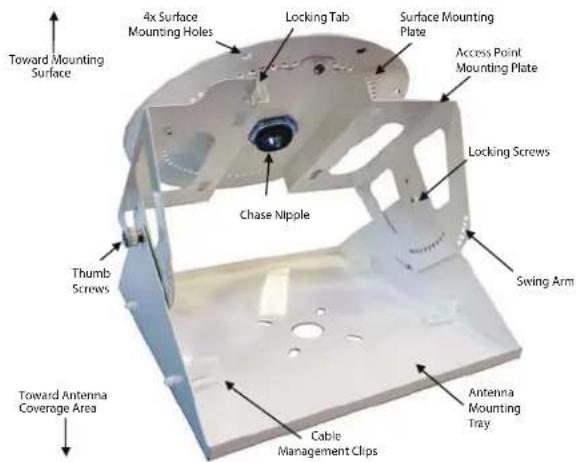
Toward Mounting Surface 4x Surface Mounting Holes Locking Tab Surface Mounting Plate Access Point Mounting Plate Locking Screws Chase Nipple Swing Arm Thumb Screws Toward Antenna Coverage Area Cable Management Clips Antenna Mounting TrayRecommended Hardware:
Dry Wall Mounting:
- 4x Wall Anchors
- 4x Dry Wall Screws that fit the holes shown in Figure 2.
Wood Wall Mounting:
- 4x Wood Screws that fit the holes shown in Figure 2.
- 4x Locking Washers
Metal Surface Mounting
- 4x Metal Screws that fit the holes shown in Figure 2.
- 4x Flat Washers
- 4x Locking Washers
Figure 1
- Major parts of the Dual Axis Co-Locating Mount. Refer to it as required for the remaining steps.
text_image
Surface Mounting Plate Chase Nipple Nut Chase Nipple Threads Figure 2Figure 2
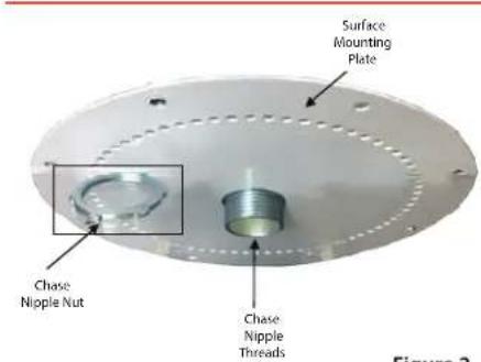
Figure 2
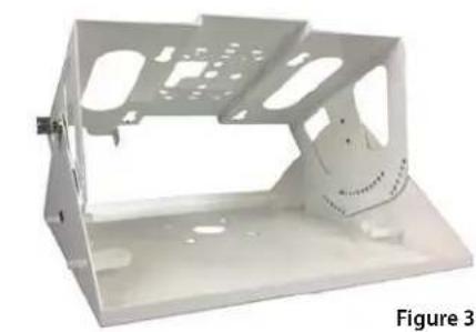
- Detach the circular Surface Mounting Plate from the Access Point Mounting Plate by unscrewing the Chase Nipple nut. Set aside the Chase Nipple nut for later use. Retain the Chase Nipple within the Surface Mounting Plate.
natural_image
White plastic enclosure with mounting holes and a small inset showing internal structure (no text or symbols)Figure 3
- Set aside the combined Access Point Mounting Plate/Antenna Mounting Tray for later use.
text_image
Surface Mounting Stand-offsFigure 4
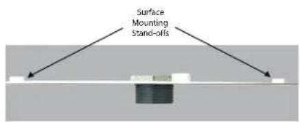
Figure 4
- Place the Surface Mounting Plate over the desired mounting location, with the four Surface Mounting Stand-Offs touching the mounting surface.
- Pull the RJ-45 cable through the Chase Nipple and allow it to hang loose.
- Insert four screws or bolts into the four Surface Mounting Holes. Tighten the screws/bolts until the Surface Mounting Plate is secure against the mounting surface.
text_image
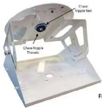
Chase Nipple Nut Chase Nipple ThreadsFigure 5
Figure 5
- Position the combined Access Point Mounting Plate/Antenna Mounting Tray so that the threaded Chase Nipple inserts into the Access Point Mounting Plate's hole. Thread the Chase Nipple nut onto the Chase Nipple and finger tighten. The mated assembly should look like Figure 5.
natural_image
Metallic mechanical component with mounting holes and a central hub, shown without any text or symbols.Figure 6
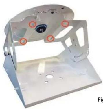
Figure 6
-
Locate the four Access Point Mounting Slots (circled) in the Access Point Mounting Plate.
-
Insert the access point's rubber mounting feet into the Access Point Mounting Slots. Slide the mounting feet inside the Mounting Slots until the access point locks into place with an audible snap.
-
Recommended step for securing the access point: Secure the access point to the Access Point Mounting Plate through the locking tab. The most common method is to thread a zip-tie through the Mounting Plate's locking tab and the access point's adjacent locking tab and tighten the zip-tie.
-
Insert the RJ-45 cable into Access Point's RJ-45 port.
natural_image
Metallic mechanical component with red circular annotations on a base plate (no visible text or symbols)Figure 7
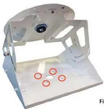
Figure 7
- Remove the nuts and washers from Antenna mounting bolts located at rear of the antenna. Push the antenna's mounting bolts through the holes in the Antenna Mounting Tray.
- Re-attach antenna washers and nuts and tighten them to hold antenna securely against Mounting Tray.
- Run antenna cables through cable management clips and attach cable connectors to the Access Point.
- Optional steps for positioning antenna:
a. The Chase Nipple nut is still only finger tight. Rotate the combined Access Point Mounting Plate/Antenna Mounting Tray until it is in the desired position. Tighten the Chase Nipple Nut so further rotation is impossible.
b. Loosen the Antenna Mounting Tray's thumb screws and locking screws. Rotate the Antenna Mounting Tray to achieve the desired antenna position. Tighten all screws.