
FA-30 - Séparateur FURUNO - Kostenlose Bedienungsanleitung
Finden Sie kostenlos die Bedienungsanleitung des Geräts FA-30 FURUNO als PDF.


Benutzerfragen zu FA-30 FURUNO
0 Frage zu diesem Gerät. Beantworten Sie die, die Sie kennen, oder stellen Sie Ihre eigene.
Eine neue Frage zu diesem Gerät stellen
Laden Sie die Anleitung für Ihr Séparateur kostenlos im PDF-Format! Finden Sie Ihr Handbuch FA-30 - FURUNO und nehmen Sie Ihr elektronisches Gerät wieder in die Hand. Auf dieser Seite sind alle Dokumente veröffentlicht, die für die Verwendung Ihres Geräts notwendig sind. FA-30 von der Marke FURUNO.
BEDIENUNGSANLEITUNG FA-30 FURUNO
FA-30 VHF SPLITTER MOUNTING PROCEDURE
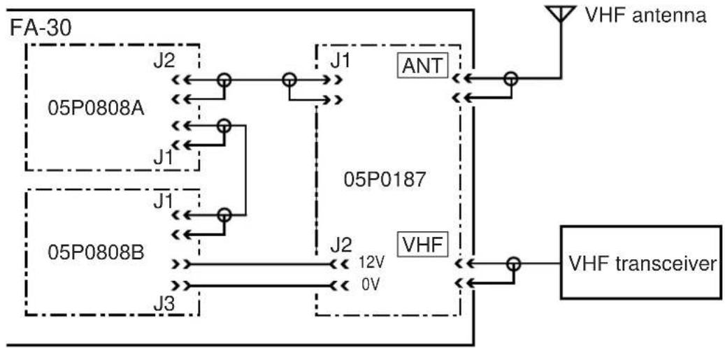
The VHF splitter enables the AIS receiver and VHF transceiver to share a single VHF antenna.
Note: The FA-30 can not receive AIS signal when the VHF transceiver is transmitting.
Equipment Lists
VHF Splitter: Type OP05-106, Code No. 000-011-704
| No. | Name Type Code No. Qty | Remarks | |||
| 1 | VHF Splitter Assembly OP05-106-1 001-024-100 1 Rear panel + pcb 05P0817 | ||||
| 2 | Installation Materials CP05-11301 001-024-110 1 Cable tie CV-70N, 1 pc. | ||||
Mounting procedure
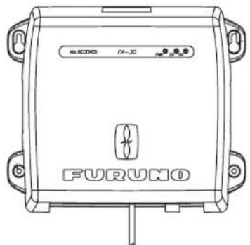
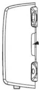
- Open the detachable cover.
text_image
FURUNO 74-30 12.5mView
natural_image
Technical line drawing of a mechanical component with two mounting holes and a central shaft (no text or symbols)Side View
-
Put fingers on both sides and pull outwards and lift up to take off.
-
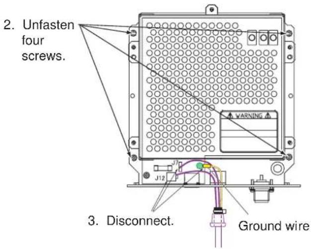
Unfasten four screws to separate the chassis from the mounting plate.
-
Disconnect plugs on J7, J12 and the ground wire from pcb 05P0807.
text_image
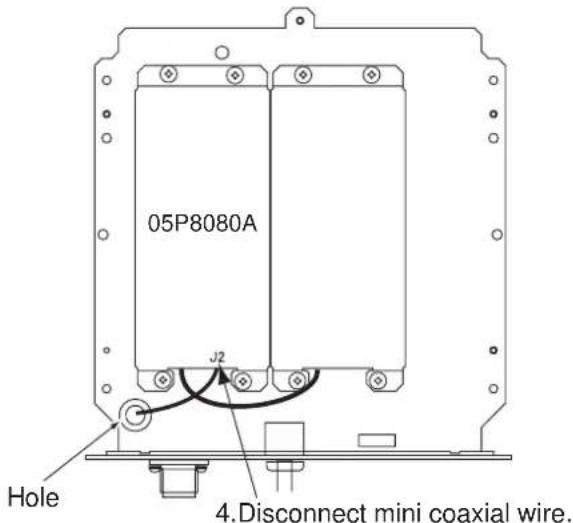
2. Unfasten four screws. 3. Disconnect. Ground wire- Turn over the chassis. Then, disconnect mini coaxial wire from J2 on pcb 05P0808A.
text_image
05P8080A J2 Hole 4.Disconnect mini coaxial wire.Bottom view
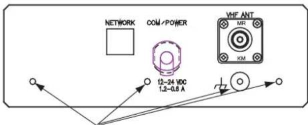
- Unfasten four screws from the rear panel to come free.
text_image
NETWORK COM/POWER VHF ANT 12-24 VDC 1.2-0.8 A KM-
Unfasten four screws.
Rear panel -
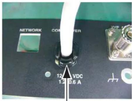
Pull out the cable assembly from the rear panel. (The rear panel may be dicarded.)
text_image
NETWORK COMPUTER 12 VDC 1.2 0.6 A-
Push strongly here and pull out the cable.
-
Pass the cable assembly to the new rear panel.
-
Connect the plugs and ground wires to original places.
-
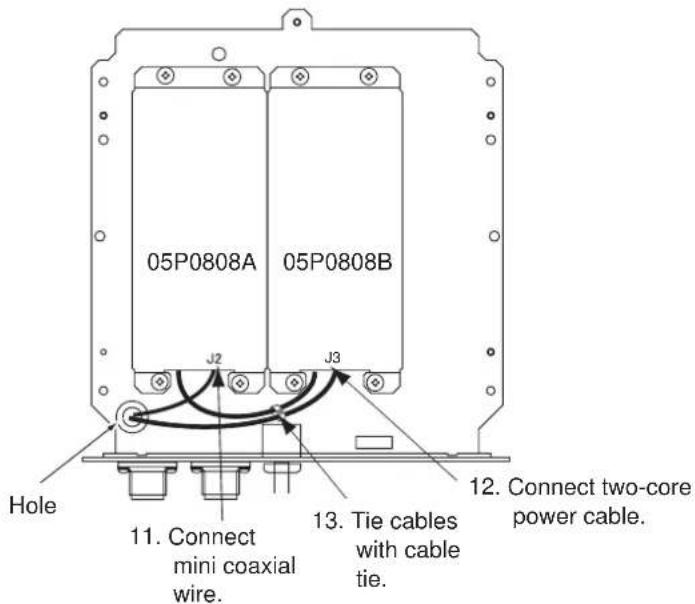
Pass two wires (two-core power cable and mini coaxial cable) from pcb 05P0817 on the new rear panel through the hole on the chassis.
Pass two-core power cable and then mini coaxial cable.
-
Fix the new rear panel to the chassis with original four screws.
-
Connect the plug of mini coaxial wire to J2 on pcb 05P0808A.
-
Connect two-core power cable to J3 on pcb 05P0808B.
-
Tie two cables with a cable tie.
-
Reassemble the chassis.
-
Connect the coaxial cable from the VHF antenna to the ANT port.
-
Connect the coaxial cable from the VHF transceiver to the VHF port.
Note: The wrong connection of coaxial cable from VHF antenna or VHF transceiver may damage this equipment.
flowchart
graph TD
    A["FA-30"] --> B["05P0808A"]
    A --> C["05P0808B"]
    B --> D["J1"]
    B --> E["J2"]
    C --> F["J1"]
    C --> G["J3"]
    D --> H["ANT"]
    E --> I["VHF"]
    F --> J["VHF transceiver"]
    G --> J
    H --> K["VHF antenna"]
    I --> K
    J --> K
    style A fill:#f9f,stroke:#333
    style B fill:#ccf,stroke:#333
    style C fill:#ccf,stroke:#333
    style D fill:#cfc,stroke:#333
    style E fill:#cfc,stroke:#333
    style F fill:#cfc,stroke:#333
    style G fill:#cfc,stroke:#333
    style H fill:#fcc,stroke:#333
    style I fill:#fcc,stroke:#333
    style J fill:#fcc,stroke:#333
    style K fill:#fcc,stroke:#333
text_image
05P0808A 05P0808B J2 J3 Hole 11. Connect mini coaxial wire. 13. Tie cables with cable tie. 12. Connect two-core power cable.Bottom view of the chassis