Venus - Nicht kategorisiert Polmar - Kostenlose Bedienungsanleitung
Finden Sie kostenlos die Bedienungsanleitung des Geräts Venus Polmar als PDF.


Benutzerfragen zu Venus Polmar
0 Frage zu diesem Gerät. Beantworten Sie die, die Sie kennen, oder stellen Sie Ihre eigene.
Eine neue Frage zu diesem Gerät stellen
Laden Sie die Anleitung für Ihr Nicht kategorisiert kostenlos im PDF-Format! Finden Sie Ihr Handbuch Venus - Polmar und nehmen Sie Ihr elektronisches Gerät wieder in die Hand. Auf dieser Seite sind alle Dokumente veröffentlicht, die für die Verwendung Ihres Geräts notwendig sind. Venus von der Marke Polmar.
BEDIENUNGSANLEITUNG Venus Polmar

text_image
POL MARVENUS
MULTI-STANDAARD CB ZENDONTVANGER Gebruikshandleiding
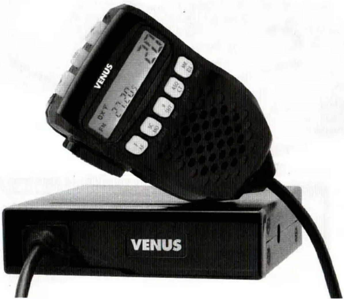
MULTISTANDARD CB TRANSCEIVER User manual
text_image
VENUS DXY 27.2015 Venus VENUSContents
Important Information 19
Controls and Connectors 20
Box Contents 21
Installation 21
Operation 22
Power ON/OFF 22
Volume Control 22
Channel Selection 22
SQ Control 23
How to start European Multi-standard support 24
Primary Function 25
Tri function button 26
SCAN 26
9 (EMG 9) 26
ASQ 26
MR (Memory Recall) 26
Secondary Function 27
AM/FM 27
MO (MONITOR) 27
SHT (EMG19) 27
CTCSS 38 Tones 28
DX 28
Third Function 29
P/SCAN (Priority Scan) 29
PRI 29
CT.SET 29
MW (Memory Write) 29
MENU function 30
Technical Specification 32
38 CTCSS Code List 33
Important Information
Please read before installing or operating. This radio is an advanced technology mobile CB transceiver that combines the latest circuit design with microprocessor control system. The following standard features are included:
- Microprocessor system.
• Large & wide angle readout for multi-function display
• Three color backlighting choices by green and amber and red color
•Full channels or priority channel scanning.
• Memory and recall function for up to 4 channels.
•Automatic squelch control System (ASQ)
•Key lock system
- Instant access to channel 9 or 19
•AM/FM selection.
- External speaker connector (3.5mm mono) and coaxial antenna socket (SO-239)
•European Multi standard support.
Safety Warnings
- Do not place your radio in the area over an air bag or in the air bag replacement area.
• Air bags inflate with great force. - If a radio is placed in the air bag deployment area and the air bag inflates, the radio may be propelled with great force and can cause serious injury to the occupants of the vehicle.
- Turn your radio off when in any area with a potentially explosive atmosphere, unless it is a type especially qualified for such use (for example, by intrinsic safe approvals).
- Sparks in such areas could cause an explosion or fire resulting in injury or even death.
- To avoid possible interference with blasting operations turn your radio OFF near electrical blasting caps or in a "blasting area" or in areas posted: "Turn off any two way radio." Obey all signs and instructions.
- Check the laws regarding the use of radios while driving and always obey them.
- In some European countries it is forbidden for the driver to keep any microphone in hands or to operate a radio during driving.
- Some countries (like Germany) make a difference between mobile phones and 2 way radios. Mobile phones are only allowed to be operated in hands free mode, while CB & commercial two way radios are still allowed even with hand microphone.
- Do not try to transmit if the antenna has not been connected
- Only use antennas tuned on 27 MHz and with a typical impedance of 50 ohm
- Never allow children to touch the transceiver
- Use the specified microphone only
- Do not place the transceiver in excessively dusty environments
- Do not operate the transceiver countinuously without running the vehicle's engine. The vehicle's battery can quickly run out.
- Servicing must be performed by qualified personnel only.
- Switch the transceiver off while refuelling or at a petrol station.
- Do not tamper with or attempt to modify the transceiver.
Controls e connectors
text_image
8 1 F AF BC MO 0 SHT ASO CT MX MXCAN PR CT SET 3 4 5 6 7 8 9 10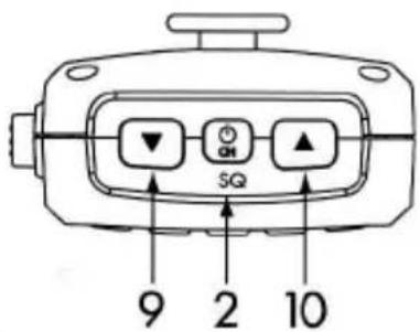
text_image
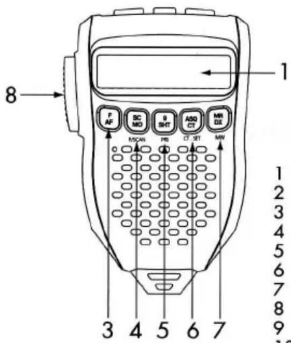
9 2 10 SQ1 LCD display
2 Long push for Power ON/OFF
3 Function selector / AM/FM selector
4 SCAN, Monitor, PSCAN
5 EMG9, EMG19/PRI channel setting
6 ASQ, CTCSS ON/OFF /CTCSS code setting
7 Memory recall, DX / Memory save
8 Push to talk
9 Volume/channel/squelch/Down
10 Volume/channel/squelch/UP
text_image
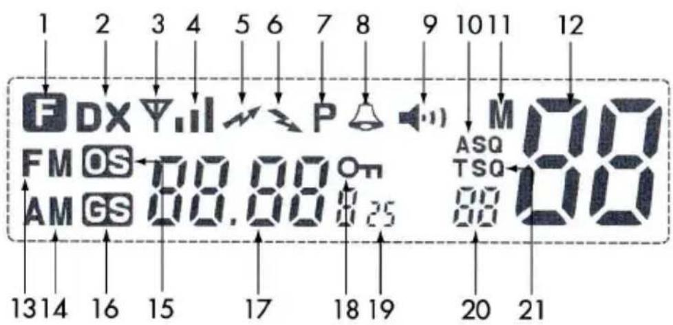
1 2 3 4 5 6 7 8 9 10 11 12 F DX Y.II P M FM OS 00.00 On ASQ AM GS 00.00 025 TSO 13 14 16 15 17 18 19 20 211 Function
2 DX
3 Antenna
4 Signal Strength
5 Transmitter Indicator
6 Receiver Indicator
7 Priority On/Off
8 Roger beep On/Off
9 Monitor ON/OFF
10 Automatic SQ
11 Memory indicator
12 Channel display
13 FM Mode
14 AM Mode
15 Open Scan (General Scan)
16 Group Scan (Priority Scan)
17 Frequency display
18 Key Lock ON/OFF
19 UK frequency display
20 CTCSS code display
21 CTCSS ON/OFF
Box contents
- 1 x RF Radio
• 1 x Controller Speaker Microphone - 1 x DC Power cord with inline fuse
- 1 x Mounting bracket with mounting screws for RF Radio
- 1 x 2m long Extension cable with a coupler
Installation
CAUTION
- When installing your radio in your vehicle, check that during installation you do not damage any wiring or vehicle components that may be hidden around the mounting position.
- If you are unsure about how to install your radio, we suggest for optimum performance you have your radio professionally installed by a CB specialist or Auto electrician. When installing the radio, avoid mounting it close to heaters or air conditioners. Do not press the PTT before installing the antenna Screw the mounting bracket and the remote head bracket to firm surfaces.
To install the radio;
1 Fix the radio bracket in a suitable location.
2 Then fix the radio in the bracket using the thumb screws.
Note
The radio contains a built-in loud speaker, the radio must be installed in an open location, an external speaker can be used as an alternative (not supplied)
Fitting the Controller Microphone Speaker
The Remote Head uses an 8 pin telephone style plug and socket:
1 Position the microphone plug so the plastic flap faces downwards, and press the plug into the socket until it 'clicks'
2 Gently press the rubber boot into the hole surrounding the socket so that the slot around the boot fits neatly inside the rim of the entry hole.
3 If required use the extension cable (supplied) to allow the radio to be installed further from Controller Speaker Microphone.
Disconnection the Remote Head/Speaker Controller Microphone
It is recommended that the remote head be left permanently connected to the radio, but if it must be disconnected, proceed as follows:
1 Lift the rubber boot and the lip of the raised area on the front panel.
2 Ease the rubber boot out of the cable entry hole and slide it along the cable away from the front panel.
3 Identify the plug locking flap, move the flap towards the plug body.
At the same time gently pull the plug from the socket.
DC Power Connection
The radio is designed for 13.8 V dc, negative earth installations only (i.e. where the negative battery terminal connects to the chassis of the vehicle). For installation on 24V system an inverter (not supplied) will need to be used.
Over voltage protection
The radio has a high voltage input detection system, to warn you if an over voltage situation occurs. Example: If the power supply voltage exceeds 17 volts DC, the display (LCD backlight) will flash in 3 different colors when the unit is turned on.
If the over voltage warning appears, you must switch your radio off and disconnect it from the power source, therefore locate the cause of the trouble.
Radio stays ON when the ignition is switched OFF
Connect the radio's negative (black) lead to the vehicle chassis, or directly to the battery's negative terminal. Connect the radio's positive (red) lead via the 2 A fuse to the battery's positive terminal. Alternatively, the positive lead could be connected at the fuse box at a point that has 13.8 volts continuously available (preferably the battery side of the ignition switch) via the 2A fuse.
Radio turns OFF with the ignition switch
Connect the radio's negative (black) lead to the vehicle's chassis, or directly to the batterie's negative terminal. The radio's positive (red) lead should be connected to an accessory point in the vehicle's fuse box via the 2 Amp fuse.
Antenna information
The antenna (not supplied) is of critical importance, to maximize your output power and receiver sensitivity.
A poor quality antenna or one not designed for the specific frequency band you are using will give poor performance. You should purchase an antenna designed for the 27MHz frequency band.
Antenna installation
1 Connect the antenna to the rear antenna socket using a PL-259 coaxial connector.
2 To obtain maximum performance from the radio, select a high quality antenna and mount it in a good location. Do not press the PTT before installing the antenna.
Optional accessories
If required you may install an external (8ohm,max 5w power) speaker fitted with 3.5mm mono plug (not supplied). There is a jack located on the rear of the radio.
Operation

text_image
SQPower On/Off
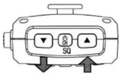
Press and hold PWR button for 2 seconds.
text_image
SQ CHVolume control
The Venus CB has Volume Up and Volume Down buttons on the microphone. Adjust to the preferred volume level.

text_image
SQChannel Selection
Briefly press the PWR button. Select the channel by pressing the Channel Up or Channel Down buttons on the microphone from 1 to 40.
The Venus CB has Channel Up or Channel Down buttons on the microphonel.
SQ Control
- This control is used to cut off or eliminate the background noise in the absence of incoming signals.
- Twice press power PWR button for Squelch adjust mode.
Venus CB has 15 preset squelch levels:
OFF - SQ OFF (monitor on condition)
1 - Max sensitivity (min squelch)
15 - Min sensitivity (max/tight squelch)
How to start the country switching (European Multi-standard support)
Venus CB has the present and future European Multi-standard support as explained below.
Multi Standard Mode
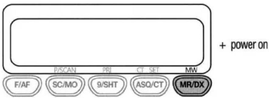
Please note that this device must operate in Italy within 26,965 \~ 27,405 MHz frequency range, as indicated in Nota 49G of the "Piano Nazionale Ripartizione Frequenze".
- Hold MR/DX button and Power on. It is menu mode.
text_image
+ power on P/SCAN PRI CT SET MW F/AF SC/MO 9/SHT ASQ/CT MR/DX- Channel up and down for your country - You select country and then press 9/SHT button to fix the country.
Now your radio will start to operate at the selected country mode.
| Display | Country Setting |
| SET E | SPAIN, ITALYFM 40CH, 4WAM 40CH, 4W |
| SET U | UKFM 40CH, 4W, CEPTFM 40CH, 4W, UK |
| SET dE | GERMANYFM 80CH, 4WAM 40CH, 1W |
| SET EU | EUFM 40CH, 4WAM 40CH, 1W |
| SET EC | CEPTFM 40CH, 4W |
| SET Po | POLANDFM 40CH, 4WAM 40CH, 4W |
Primary function
Tri-Function buttons
text_image
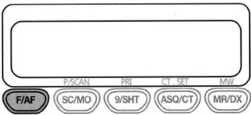
P/SCAN PRI CT. SET MW F/AF SC/MO 9/SHT ASQ/CT MR/DXTo use the primary function (F,SC,9,ASQ,MR) press the required button. To use the secondary function (AF, MO, SHT, CT, DX) press and hold the button for 2 seconds. To use the third function (P/SCAN, PRI, CT.SET, MW), press F/AF and press the required button.
SCAN
text_image
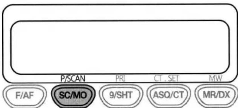
P/SCAN PRI CT . SET MW F/AF SC/MO 9/SHT ASQ/CT MR/DXVenus CB transceiver incorporates a scanning feature. The radio will scan through all 40 (80) channels and will stop at BUSY channel. The default stay time is 5 seconds after conversation has stopped and then it will resume scanning.
1 To start scanning turn on the power first and adjust the volume and squelch.
2 Press SC/MO button to start scanning. The word "OS" will appear in the LCD.
3 The unit will start scanning.
4 If you want to stop scanning you can push SC/MO button again or press the push-to-talk button. This will shut off the scanning function and transmit on that channel.
9 (EMG 9)
text_image
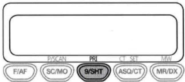
P/SCAN PRI CT SET MW F/AF SC/MO 9/SHT ASQ/CT MR/DXThe EMG (Emergency) button is for instant access to international Calling & Emergency channel 9, which is monitored by all truckers and many CB users and in some regions even by road safety organizations. if you need any help or assistance, it is a good idea to call on this channel 9.
Truckers can be reached in most cases in AM mode. The emergency channel is also used on the German highways as warning system in case of accidents, road maintenance or serious traffic jams with collision danger, if you pass a special beacon on your lane and a dangerous situation may be in front of you, you will be warned by alarm tones and voice announcement. With the EMG key you can toggle between CH9 and your previously used channel.
The other, often used calling channel is Channel 19, if you want to use CH19, press for 2 seconds 9/SHT button.
ASQ
text_image
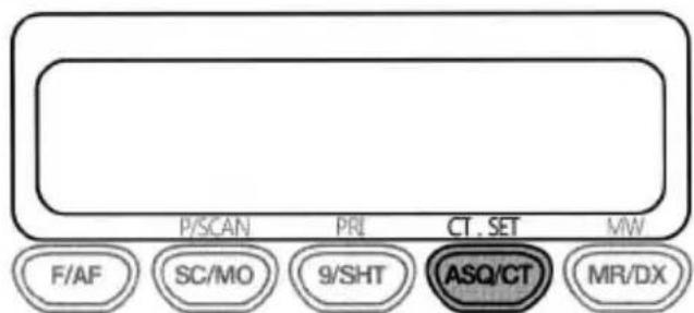
P/SCAN PRI CT. SET MW F/AF SC/MO 9/SHT ASQ/CT MR/DXAs already mentioned in the squelch chapter, the ASQ is a feature that allows the radio to receive an incoming signal which is stronger than the surrounding noise level. This automatic switching function does not need any adjustment and works fully automatic. It opens at any signal which is good enough to be understood.
The sensitivity of the ASQ system is very good. It can even open at signal strengths below the nominal maximum usable sensitivity. The only criterion is the reduction of noise on the receiving channel. However, the ASQ function is limited to normal receiving condition on the CB band. During periods of strong over-range wave propagation, strong sun-spot activates, it could be better to use the standard squelch instead of the ASQ.
MR (Memory Recall)
text_image
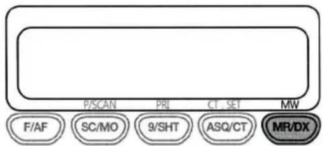
P/SCAN PRI CT_SET MW F/AF SC/MO 9/SHT ASQ/CT MR/DXTo access memorized channels simply press the "MR/DX" button and choose the desired memory channel from M1 to M4 by pressing on buttons from F/AF to ASQ/CT.
Secondary function
AM/FM
text_image
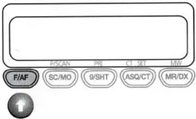
P/SCAN PR CT. SET MW F/AF SC/MO 9/SHT ASQ/CT MR/DXYou can select AM or FM modulation by pressing the F/AF button for 2 seconds. Please note that in the German 80 CH system it is possible (and allowed) to listen in AM on all 80 channels but transmit is only possible on CH 1 - 40 in AM. During receive mode, The bar graph shows the strengths of the received signal, during transmission, it shows the relative output power.
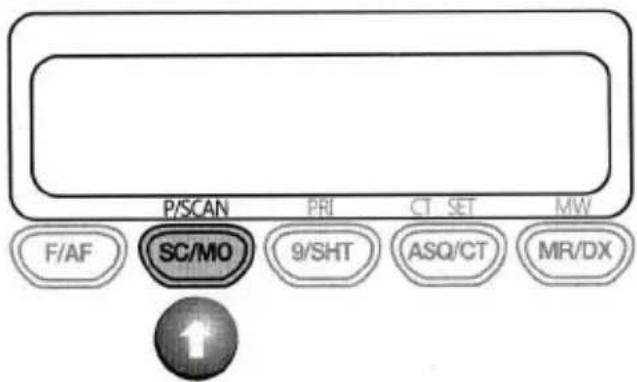
MO (Monitor)
text_image
P/SCAN PRI CT SET MW F/AF SC/MO 9/SHT ASQ/CT MR/DXThe monitor feature is used to listen to weak signal that repeatedly open and close the squelch without changing the squelch setting. When receiving a weak signal, push for 2 seconds this button to open the squelch completely.
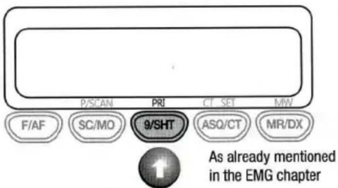
SHT (EMG 19)
text_image
P/SCAN PRI CT SET MW F/AF SC/MO 9/SHT ASQ/CT MR/DX As already mentioned in the EMG chapterAs already mentioned in the EMG chapter
CT (CTCSS)
text_image
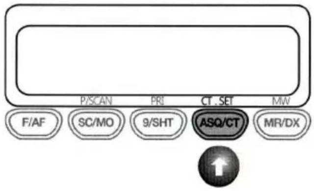
P/SCAN PRI CT . SET MW F/AF SC/MO 9/SHT ASQ/CT MR/DX ↑CTCSS uses a sub-audile tone to open and close the squelch on your radio. This will allows a number of users to share the same channel without disturbing one another.
Technically, CTCSS system can only work in FM mode and not in AM.
The CTCSS mode allows you to create closed user groups within the CB band and it avoids any opening of the squelch by other stations. Only stations with the correct CTCSS code on their transmissions can be heard.
Enabling CTCSS on a channel
our radio is supplied with CTCSS Tone CH 01 pre-programmed in all CB channels but not-activated (CTCSS Tone off condition) as a factory default.
You can activate CTCSS function by pressing ASQ/CT button for 2 seconds and you can select whether CTCSS Tone will work in TX mode only or both TX and RX mode as follow.
1 Press ASQ/CT button for 2 seconds, then the icon "T" will appear in LCD.
The "T" means CTCSS Tone can work in Transmitting mode only.
2 Press and hold ASQ/CT button one more time, the icon "TSQ" will appear in LCD. The "TSQ" means CTCSS Tone can work in both Transmitting and Receiving mode. When you want to change CTCSS tone channel, you can select CT.SET button by pressing F/AF button and ASQ/CT.
Then the pre-programmed Tone CH 01 will be blinking in LCD.
You can select the desired channel and press ASQ/CT button to fix the selected new Tone CH.
Note: CTCSS Tone CH can be programmed different in each CB channel but its use condition such TX only, TX/RX only or Tone off condition is programmed same to all CB channels.
DX
text_image
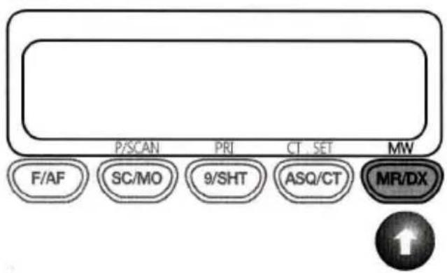
P/SCAN PRI CT SET MW F/AF SC/MO 9/SHT ASQ/CT MR/DXThe DX feature allows long distance communication in some season.
The DX setting condition is maximum user receiving sensitivity condition. When DX is not selected, you can communicate within local area.
Third Function PSCAN (Priority SCAN)
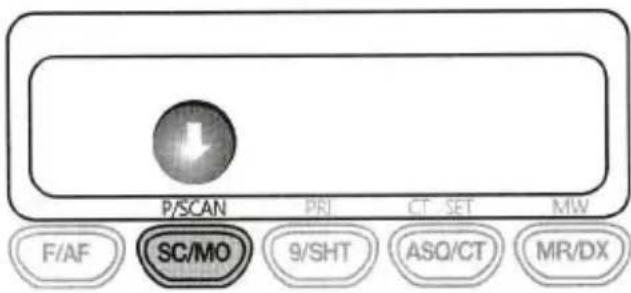
text_image
P/SCAN PRI CT SET MW F/AF SC/MO 9/SHT ASQ/CT MR/DX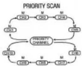
flowchart
graph TD
    A["CHS"] --> B["M"]
    B --> C["CHS"]
    C --> D["M"]
    D --> E["CHS"]
    E --> F["M"]
    F --> G["CHS"]
    G --> H["M"]
    H --> I["CHS"]
    I --> J["M"]
    J --> K["CHS"]
    K --> L["M"]
    L --> M["CHS"]
    M --> N["M"]
    N --> O["CHS"]
    O --> P["M"]
    P --> Q["CHS"]
    Q --> R["M"]
    R --> S["CHS"]
    S --> T["M"]
    T --> U["CHS"]
    U --> V["M"]
    V --> W["CHS"]
    W --> X["M"]
    X --> Y["CHS"]
    Y --> Z["M"]
    Z --> A
    style A fill:#f9f,stroke:#333
    style B fill:#f9f,stroke:#333
    style C fill:#f9f,stroke:#333
    style D fill:#f9f,stroke:#333
    style E fill:#f9f,stroke:#333
    style F fill:#f9f,stroke:#333
    style G fill:#f9f,stroke:#333
    style H fill:#f9f,stroke:#333
    style I fill:#f9f,stroke:#333
    style J fill:#f9f,stroke:#333
    style K fill:#f9f,stroke:#333
    style L fill:#f9f,stroke:#333
    style M fill:#f9f,stroke:#333
    style N fill:#f9f,stroke:#333
    style O fill:#f9f,stroke:#333
    style P fill:#f9f,stroke:#333
    style Q fill:#f9f,stroke:#333
    style R fill:#f9f,stroke:#333
    style S fill:#f9f,stroke:#333
    style T fill:#f9f,stroke:#333
    style U fill:#f9f,stroke:#333
    style V fill:#f9f,stroke:#333
    style W fill:#f9f,stroke:#333
With Priority Scan function the Radio scans for activity, but in addition, it also inserts your Priority Channel into the scan sequence.
This means that your Priority Channel will be monitored regularly while scanning to ensure that no calls are missed. Any signals received on your Priority Channel will take precedence over any signal received on the other channels.
Pushing SC/MO button allows you to monitor the Priority Channel while scanning other channels in the P/Scan mode.
To activate this function push F/AF and SC/MO buttons.
PRI (Priority)
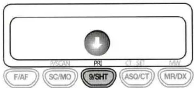
text_image
P/SCAN PRI CT SET MIN F/AF SC/MO 9/SHT ASO/CT MR/DXTo store a Priority channel, press the F/AF and PRI buttons. The letter "P" will appear when the priority channel is set. The channel you selected as your Priority Channel will then be automatically monitored during the Priority Scan.
Note: You can only store one channel as your priority channel
CT.SET

text_image
P/SCAN PRI CT. SET MW F/AF SC/MO 9/SHT ASQ/CT MR/DXThis feature allows you to receive signals only from callers who have selected the same CTCSS tone.
1 Press F/AF and ASQ/CT button, The CTCSS channel will be blinking.
2 Select channel 1 to 38 tones with UP/DOWN buttons and then repeat above 1 process to fix other channels tone.
MW (Memory Write)
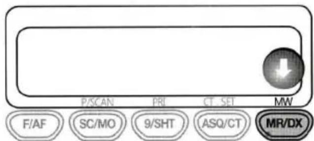
text_image
P/SCAN PRI CT SET MW F/AF SC/MO 9/SHT ASQ/CT MR/DXThis MW button is used to store any channel in each memory location from M1 to M4. To store channel:
1 Select the desired channel with UP/DOWN buttons
2 Press F/AF +MW buttons
3 You can choose any memory location from F/AF (M1) to ASQ/CT(M4).
Menu Function
This MENU function can control six Sub menu functions in sequence.
- Power off
- You must press hold the MR/DX button and than power On.
- The display will show "Set E".
- Now press F/AF button.
- You can change SUB menu setting by Up and down button.
| Control | Functions | STEP | Display | Default |
| MEMU | CE-MULTI SET | SET E | E | |
| LIGHT | Off,1,2,3 | LIGHT 3 | 3 | |
| BEEP | On | BEEP off | On | |
| Roger beep | On | r9b of | Off | |
| TOT | 1,2,3,4min | tot of | Off | |
| SCAN stop time control | 5,10,15min sec | stop PS | PS |
Light
You can select from three color options for the LCD backlight. The three options are amber, red and green.
Key Beep On/Off
The Beep tone emits a tone when you press any of the buttons on the Microphone (except PTT switch)
Roger Beep
This function emits a beep once the transmission is finished.
TOT (Time of Timer)
The Venus has 4 kinds time of timer function for TX. The display 1 mean time of timer setting 1 minute. "TOT - On" will appear in the display with error beep sound to indicate that the TOT has activated.
Scan stop control
The scan resume condition can be set as a pause (p5) or time scan (5/10/15).
When a signal disappears, scan resume after 5 sec.
5/10/15: Scan paused for 5,10 or 5 sec. when a signal is detected, then resumes after set timer.
P5: Scan pauses until the signal disappears and then resumes after 5 sec.
Factory reset
If the radio's display locks up or stops functioning properly, you might need to reset your radio. This procedure clears all the information you have stored in your radio.
Before you reset CB radio, try turning it off and on again.
If your CB radio is still not functioning correctly you may need to reset the CB radio!
While holding the F/AF button, turn the CB radio on, "rESEt" will be displayed for 1 to 2 seconds.
The radio will then return to its factory default status.
Key lock
The Key lock feature allows you lock all buttons on the radio except F/9/ASQ/PWR. So they can't be activated by wrong entries or accidentally. Press F/AF and PTT. Use the same procedure later again to unlock the buttons again.
Specifications
| General | |
| Transmitter | Crystal Controlled PLL Synthesizer |
| Receiver | Double Conversion and Superheterodyne System |
| Voltage Operation | 13.8V dc |
| For supply over 17V, automatic detection of over voltage | |
| Switch on blinking of LCD display at three colors rotation. | |
| Channel Step | 10kHz |
| Dimension (H x W x D) | microphone: 95 x 58 x 25 mm main unit: 29 x 108 x 136 mm |
| 3.5mm External SPK Jack | Mono Type |
| Antenna connector | SO-239 (50 Ohms socket for PL-259 plugs) |
| Condensor Microphone | Corresponds to 6 pin standard wiring |
| Transmitter | |
| RF Output Power | FM: 4W - AM: 4W (AM: 1W in german band) |
| Frequency Range | See table pag. 22 |
| Frequency Error | < ±600Hz |
| Microphone Sensitivity | 2.5mV (1250Hz input) |
| Modulation Capability | AM 80% - FM 2.0 kHz |
| Receiver | |
| Maximum Sensitivity at 12dB SINAD | AM : -120dBm - FM: -121dBm |
| Squelch Close sensitivity | -126dBm at SQ1 - -47dBm at SQ15 |
| Auto Squelch | -120dBm |
| S/N Ratio | 40dB |
| Distortion | <5% |
| Signal meter sensitivity at maximum | -67dBm at 3 digit |
| Audio Output Power | Minimum 2 W at 8 ohms |
| Test Condition | |
| Power Source | 13.8 V dc |
| Antenna Impedance | 50 Ohm |
| Audio Load Impedance | 8 Ohm |
38 CTCSS Code list
| Code | Frequency (Hz) | Code | Frequency (Hz) |
| OFF | OFF | 20 | 131.8 |
| 1 | 67.0 | 21 | 136.5 |
| 2 | 71.9 | 22 | 141.3 |
| 3 | 74.4 | 23 | 146.2 |
| 4 | 77.0 | 24 | 151.4 |
| 5 | 79.7 | 25 | 156.7 |
| 6 | 82.5 | 26 | 162.2 |
| 7 | 85.4 | 27 | 167.9 |
| 8 | 88.5 | 28 | 173.8 |
| 9 | 91.5 | 29 | 179.9 |
| 10 | 94.8 | 30 | 186.2 |
| 11 | 97.4 | 31 | 192.8 |
| 12 | 100.0 | 32 | 203.5 |
| 13 | 103.5 | 33 | 210.7 |
| 14 | 107.2 | 34 | 218.1 |
| 15 | 110.9 | 35 | 225.7 |
| 16 | 114.8 | 36 | 233.6 |
| 17 | 118.8 | 37 | 241.8 |
| 18 | 123.0 | 38 | 250.3 |
| 19 | 127.3 | 39 |
Declaration of Conformity
Hereby Polmar Srl, declares that this CB transceiver brand Polmar, mod. Venus is in compliance with the essential requirements and other relevant provisions of Directive 1999/5/CE.

POLMAR Syl
Sede operativa: F.zea Adigrat 2 -20133- Milano
Sede Legalet: Rattie Cavour, 3 -20121-Mann
Cell, 134 5087779
E-mail: poinat.azhianson.it
500 Internet: www.42money.com
Ref: SCLG.2011.TR.06
Declaration of Conformity
I hereby declare that the product:
Type:
27 MHz citizen's band transceiver brand Polmar model Venus
satisfies all the technical regulations applicable to the product within the scope of Council Directives, 2006/95/IC, 89/336/TEC (and its amendments) and 99/05/EC.
Standard dtls:
EN 60950-1: 2006/A11: 2009; EN 301 489-1 V1.8.1; EN 301 489-13 V1.2.1;
EN 300 135-2 V1 2.1 (2008-02); EN 310 433-2 V1 2.1 (2010-07)
All essential radio test suites have been carried out.
Notified Body:
Name:
Istituto Superiore delle Comunicazioni e delle Tecnologie dell'informazione (I.S.C.T.I.)
Address:
Viale America, 201
00144 Roma
Italy
Identification Number:
0641
Manufacturer or Authorized Representative:
Name:
Polemar St
Address:
Plaza Cavour, 3
2012 Milano
Italy
Telephone no. +39 334 5007779
E-mail: goimar.sri@olice.it
This declaration is issued under the sole responsibility of the Manufacturer and, if applicable, his Authorized Representative.
Point of contact:
Name: Mrs. Norma Uggeri
Tel.no. +39 334 5007779
E-mail:polmar.srd@alice.it
Milano, 28 luglio 2011
Signature
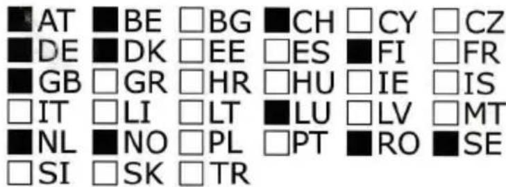
List of intended countries of use
text_image
AT BE BG CH CY CZ DE DK EE ES FI FR GB GR HR HU IE IS IT LI LT LU LV MT NL NO PL PT RO SE SI SK TRC€0648①
CE This symbol, on the serial number seal, means that the equipment complies with the essential requirements on the European Radio and Telecommunication Terminal Directive 1999/05/EC.
This warning symbol indicates that this equipment operates in non-harmonized frequency bands and/or may be subject to licensing conditions in the country of use. Be sure to check that you have the correct version of this radio or the correct programming of this radio, to comply with national licensing requirements.
GEBRUIKSINFORMATIE
Conform artikel 13 van de Richtlijn van 25th juli 2005, nr. 15 "Implementatie van Richtlijnen 2002/95/EC, 2002/96/EC en 2003/108/EC, m.b.t. de reductie in gebruik van schadelijke stoffen in elektrische en elektronische apparatuur, naast afvalverwerking"

Het doorgekruiste afvalbaksymbool op de apparatuur betekent dat het product aan het einde van de levensduur ervan gescheiden van ander afval moet worden ingezameld.
De gebruiker moet daarom de bovengenoemde apparatuur naar een geschikt centrum voor gescheiden inzameling van elektronisch en elektrisch afval brengen, of terugbrengen naar het verkooppunt wanneer een nieuw apparaat wordt aangeschaft van een gelijksoortig type, met een verhouding van één op één.
Gescheiden inzameling van afval voor daaropvolgende recycling, behandeling en milieuvriendelijke verwijdering van afgedankte apparatuur helpt mogelijke negatieve effecten op het milieu en de volksgezondheid te voorkomen en bevordert recycling van de grondstoffen in de apparatuur.
Illegaal afdanken van het product door de gebruiker zal worden gestraft d.m.v. toepassing van administratieve kosten zoals bepaald is door Richtlijn nr. 22/1997 (artikel 50 en volgens Richtlijn nr. 22/1997).
Raadpleeg bij twijfel en/of vragen altijd uw dealer.
Drukfouten voorbehouden.
Geïmporteerd en gedistributeerd door:

text_image
K-PO®KBC IMPORT / EXPORT
ARGONSTRAAT 6
6718 WT EDE
HOLLAND
WWW.K-PO.COM
INFO@K-PO.COM
TEL. +31 318 552491
FAX +31 318 437801