MS400080H - Wi-Fi-Repeater Microsens - Kostenlose Bedienungsanleitung
Finden Sie kostenlos die Bedienungsanleitung des Geräts MS400080H Microsens als PDF.


Benutzerfragen zu MS400080H Microsens
0 Frage zu diesem Gerät. Beantworten Sie die, die Sie kennen, oder stellen Sie Ihre eigene.
Eine neue Frage zu diesem Gerät stellen
Laden Sie die Anleitung für Ihr Wi-Fi-Repeater kostenlos im PDF-Format! Finden Sie Ihr Handbuch MS400080H - Microsens und nehmen Sie Ihr elektronisches Gerät wieder in die Hand. Auf dieser Seite sind alle Dokumente veröffentlicht, die für die Verwendung Ihres Geräts notwendig sind. MS400080H von der Marke Microsens.
BEDIENUNGSANLEITUNG MS400080H Microsens
MICROSENS
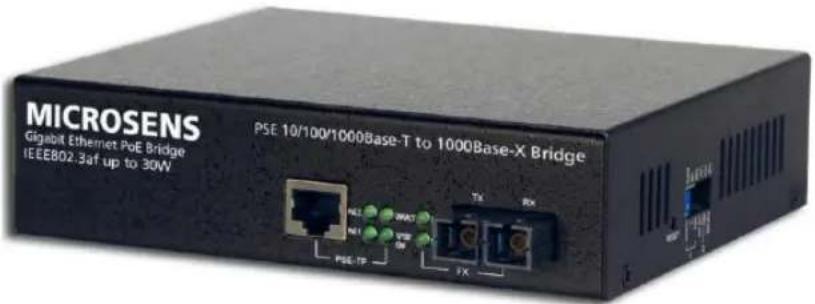
text_image
MICROSENS Gigabit Ethernet PoE Bridge IEEE802.3af up to 30W PSE 10/100/1000Base-T to 1000Base-X Bridge TX RX NE2 3MWT NET VSB ON PSE-TP FXUser's Manual
Gigabit Ethernet PoE Bridge MS40008xH
Table of Contents
CAUTION....3
ELECTRONIC EMISSION NOTICES 3
- OVERVIEW......4
- MODEL DESCRIPTION....4
- CHECKLIST 5
- INSTALLING THE BRIDGE....5
- WDM SINGLE FIBER MODEL....8
- LINK FAULT PASS THROUGH....9
- LED DESCRIPTION 11
- DIP SWITCH AND RESET BUTTON....11
- CABLE CONNECTION PARAMETER 12
- POE PSE TP-FIBER TECHNICAL SPECIFICATIONS 12
Caution
Circuit devices are sensitive to static electricity, which can damage their delicate electronics. Dry weather conditions or walking across a carpeted floor may cause you to acquire a static electrical charge.
To protect your device, always:
- Touch the metal chassis of your computer to ground the static electrical charge before you pick up the circuit device.
- Pick up the device by holding it on the left and right edges only.
Electronic Emission Notices
Federal Communications Commission (FCC) Statement
This equipment has been tested and found to comply with the limits for a class A computing device pursuant to Subpart J of part 15 of FCC Rules, which are designed to provide reasonable protection against such interference when operated in a commercial environment.
European Community (CE) Electromagnetic Compatibility Directive
This equipment has been tested and found to comply with the protection requirements of European Emission Standard EN55022/EN60555-2 and the Generic European Immunity Standard EN50082-1.
| EMC: | EN55022(1988)/CISPR-22(1985) | class A |
| EN60555-2(1995) | class A | |
| EN60555-3 | ||
| IEC1000-4-2(1995) | 4K V CD, 8KV, AD | |
| IEC1000-4-3(1995) | 3V/m | |
| IEC1000-4-4(1995) | 1KV – (power line), 0.5KV – (signal line) |
1. Overview
10/100/1000Base-T to 1000Based-SX/LX IEEE802.3z/ab GbE media bridge, which allows two types of network segments to be connected easily and inexpensively. Complied with IEEE802.3af (extended version with max. PoE output power consumption up to 30W) Power-Over-Ethernet standard, this AC powered PoE media bridge is a Power Sourcing Equipment (PSE) which combines data received over a TP link with -48VDC power, providing power to IEEE802.3af of powered device (PD) over the existing CAT5 UTP cable. The bridge includes a PD signature sensing and power monitoring features. Other features include over-current protection, under-current detection and fault protection input. We are using "PSE+" to represent the high power PoE output max. 30W.
The LFP (Link Fault Pass-through) allows the media bridge to monitor both the fiber and copper RX ports for loss of signal. In case of a loss of RX signal on one media port, the bridge will automatically disable the TX signal to the other media port, thus passing through the link fault. FEF (Far End Fault) enables the bridge to stop sending link pulse to the link partner once a loss of the fiber RX signal is encountered. Then the link partner will synchronously stop sending data. FEF prevents loss of valuable data transmitted over invalid link. Combining LFP and FEF troubleshooting features of MS40008xH, both end devices can be notified of a loss of fiber link.
- Model Description
| Model | Description |
| PoE PSE TP-Fiber SC | 10/100/1000Base-T to 1000Base-SX PoE PSE+ GbE bridge, MM SC |
| PoE PSE TP-Fiber SC.Sxx | 10/100/1000Base-T to 1000Base-LX PoE PSE+ GbE bridge, SM SC 10/30/50km |
| PoE PSE TP-Fiber ST | 10/100/1000Base-T to 1000Base-SX PoE PSE+ GbE bridge, MM ST |
| PoE PSE TP-Fiber BSx.Sxx | 10/100/1000Base-T to 1000Base-LX PoE PSE+ GbE bridge, SM Bidi SC 10/20km, 1310nm/1550nm |
| PoE PSE TP-Fiber LC | 10/100/1000Base-T to 1000Base-SX PoE PSE+ GbE bridge, MM LC |
| PoE PSE TP-Fiber LC.Sxx | 10/100/1000Base-T to 1000Base-LX PoE PSE+ GbE bridge, SM LC 10/30/50km |
3. Checklist
Before you start installing the bridge, verify that the package contains the following:
— The PoE PSE+ TP-Fiber Bridge
— AC Power Cord
—This User's Manual
Please notify your sales representative immediately if any of the aforementioned items is missing or damaged.
4. Installing the Bridge
PSE+ TP-Fiber Bridge with Powered Device (PD)
⇒ Connect the PSE+ bridge to an AC power source
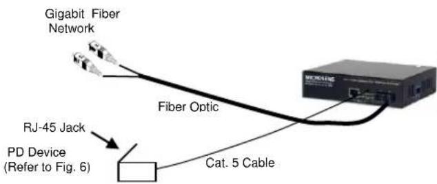
⇒ Install the TP media cable to the IEEE 802.3af PD device (See Fig. 2)
Note: It can work as a pure bridge that connects to the non-PoE converter.
⇒ Install the media cable for network connection
Warning:
⇒ Verify that the AC input conforms to your country AC power requirement and then insert the power plug
⇒ Ensure that the power of PSE device is turned on
⇒ Install the media cable for network connection
| TP Port | 10/100Base-TXAuto-NegotiationAuto-MDIXflow control for Full-Duplexbackpressure for Half-Duplex |
| 1000Base-TXAuto-Negotiation modeAuto-MDIX only for Auto-Negotiationflow control for Full-Duplex only | |
| Fiber Port | 1000Base-SX/LXwith NWay flow controlLink partner must be 1000FDX with NWay flow control |
text_image
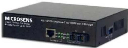
MICROSENS USB port Ethernet Port Bridge MISI 10/10V/1000Base-T to 1000Base-X Bridge MISI 10/10V/1000Base-T to 1000Base-X BridgeFig. 1 The View of PoE PSE Bridge
text_image
Gigabit Fiber Network Fiber Optic RJ-45 Jack PD Device (Refer to Fig. 6) Cat. 5 CableFig. 2 Connection among PSE PoE Bridge, Fiber and TP Cables
flowchart
graph LR
    A["1000Base-X Fiber Network Converter/Switch"] -->|RX TX| B["Cooperable Fiber"]
    B --> C["PoE PSE TP-to-GbE Fiber Converter"]
    C --> D["AC"]
    E["PoE PD or PoE Splitter"] --> F["Switch"]
    F --> G["Switch"]
    style A fill:#f9f,stroke:#333
    style B fill:#ccf,stroke:#333
    style C fill:#cfc,stroke:#333
    style D fill:#fcc,stroke:#333
    style E fill:#ffc,stroke:#333
    style F fill:#cff,stroke:#333
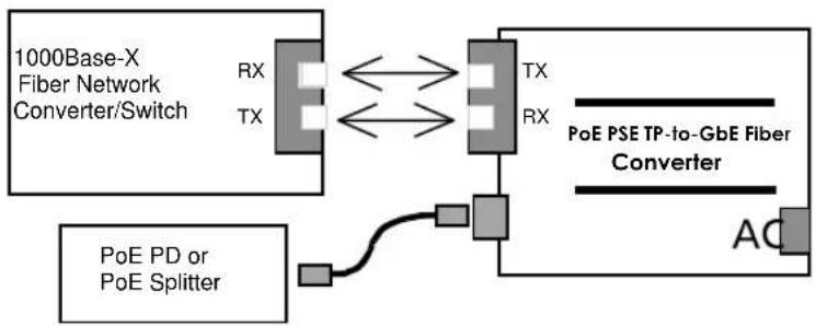
Fig. 3 PSE to PD or PoE Splitter
text_image
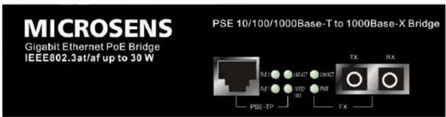
MICROSENS Gigabit Ethernet PoE Bridge IEEE802.3at/af up to 30 W PSE 10/100/1000Base-T to 1000Base-X Bridge RX TX FX PSE-TP RE:5 RE:6 RE:7 PRE:7 PRE:8 PRE:9 PRE:10 PRE:11 PRE:12 PRE:13 PRE:14 PRE:15 PRE:16 PRE:17 PRE:18 PRE:19 PRE:20 PRE:21 PRE:22 PRE:23 PRE:24 PRE:25 PRE:26 PRE:27 PRE:28 PRE:29 PRE:30 PRE:31 PRE:32 PRE:33 PRE:34 PRE:35 PRE:36 PRE:37 PRE:38 PRE:39 PRE:40 PRE:41 PRE:42 PRE:43 PRE:44 PRE:45 PRE:46 PRE:47 PRE:48 PRE:49 PRE:50Fig. 4 PoE PSE Bridge Front Panel
text_image
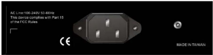
AC Line:100-240V 50-60Hz This device complies with Part 15 of the FCC Rules CE MADE IN TAIWANFig. 5 PoE PSE Bridge Rear Panel
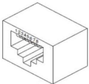
The PoE PSE+ bridge may auto-detect PD and provide power via one of two valid four-wire connections. In each four-wire connection, the two conductors associated with a pair each carry the same nominal current in both magnitude and polarity. Refer to following figure in conjunction with PSE pinout alternative table, illustrates the valid alternatives.
PSE Pinout Alternative Table
| Conductor | Alternative A (MDI-X) | Alternative B (All) |
| 1 | Negative V_Port | |
| 2 | Negative V_Port | |
| 3 | Positive V_Port | |
| 4 | Positive V_Port | |
| 5 | Positive V_Port | |
| 6 | Positive V_Port | |
| 7 | Negative V_Port | |
| 8 | Negative V_Port |
natural_image
Isometric view of a 3D rectangular device with internal channel structure (no text or symbols)PD and PSE Eight-Pin Modular Jack (RJ-45)
Note:
IEEE802.3af assigns pairs on the RJ-45 connector pinout as below: Alternative A PSE: 48V via TP pin 1, 2, 3, 6 Alternative B PSE: 48V via TP pin 4, 5, 7, 8
5. WDM Single Fiber Model
The TP-Fiber bridge is specially designed with an optic Wavelength Division Multiplexing (WDM) model that can transport bi-directional full duplex signal over a single fiber simultaneously.
| Single Fiber Model | TX, RX Wavelength | |
| 1310nm Single-Mode 10Km* 20Km models are option | TX (Transmit) | 1310nm |
| RX (Receive) | 1550nm | |
| 1550nm Single-Mode 10Km* 20Km models are option | TX (Transmit) | 1550nm |
| RX (Receive) | 1310nm | |
Note:
The 1310nm and 1550nm models must be installed in pairs, i.e., install 1310nm model at one end and 1550nm model at the other one.
text_image
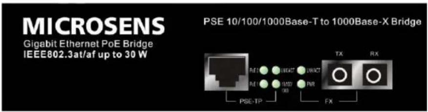
MICROSENS Gigabit Ethernet PoE Bridge IEEE802.3at/af up to 30 W PSE 10/100/1000Base-T to 1000Base-X Bridge PSE-TP PSE-TP PSE-TP PSE-TP TX RX FXFig.7 PoE PSE WDM Single Fiber Bridge Front Panel
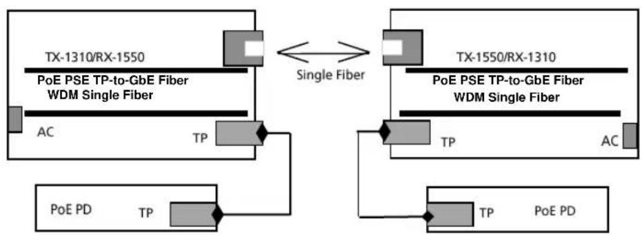
flowchart
graph TD
    A["TX-1310/RX-1550\nPoE PSE TP-to-GbE Fiber\nWDM Single Fiber"] <-->|Single Fiber| B["TX-1550/RX-1310\nPoE PSE TP-to-GbE Fiber\nWDM Single Fiber"]
    B --> C["TP"]
    C --> D["AC"]
    C --> E["TP"]
    E --> F["POE PD"]
    F --> G["TP"]
    G --> H["POE PD"]
Fig. 8 Power from PSE to PD
6. Link Fault Pass Through
The Bridge model of LFP (link fault pass through) in TX/FX bridge application is controlled by the software and instantly take effect. Link status on one port is propagated to the other port to notice the remote nodes. If TP port is unplugged, this bridge stops transmission on fiber port. This causes the remote fiber node link to fail. LED shows the link failure on both TP and fiber ports. If fiber link fails, this bridge restarts auto-negotiation on TP port but always stays in the link failure state. This causes the remote TP node link to fail. LED also shows the link failure on both TP and fiber ports. Refer to Fig. 9 shown below for the normal status when the link succeeds. Also refer to Fig. 10 and Fig. 11 for the erroneous status when TP cable A, fiber cable B or C fails to connect.
Note: Link fault pass through (LFP) function only takes effect as S1-Bit2 (see Fig. 15) is enabled. Disabled S1-Bit2 will turn this bridge into a general one.
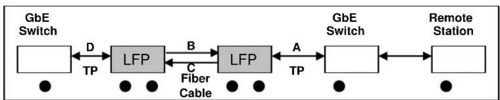
flowchart
graph LR
    A["GbE Switch"] -->|D TP| B["LFP"]
    B -->|B C Fiber Cable| C["LFP"]
    C -->|A TP| D["GbE Switch"]
    D --> E["Remote Station"]
    style A fill:#fff,stroke:#000
    style B fill:#ccc,stroke:#000
    style C fill:#ccc,stroke:#000
    style D fill:#fff,stroke:#000
    style E fill:#fff,stroke:#000
Fig. 9 Normal status via LFP converter

flowchart
graph LR
    A["GbE Switch"] -->|D TP| B["LFP"]
    B -->|B C Fiber Cable| C["LFP"]
    C -->|A TP| D["GbE Switch"]
    D --> E["Remote Station"]
    style A fill:#fff,stroke:#000
    style B fill:#ccc,stroke:#000
    style C fill:#ccc,stroke:#000
    style D fill:#fff,stroke:#000
    style E fill:#fff,stroke:#000
Fig. 10 The status as TP Cable A or D is broken

flowchart
graph LR
    A["GbE Switch"] -->|D TP| B["LFP"]
    B -->|B C Fiber Cable| C["LFP"]
    C -->|A TP| D["GbE Switch"]
    D --> E["Remote Station"]
    style A fill:#fff,stroke:#000
    style B fill:#ccc,stroke:#000
    style C fill:#ccc,stroke:#000
    style D fill:#fff,stroke:#000
    style E fill:#fff,stroke:#000
Fig. 11 The status as Fiber Cable B or C is broken

flowchart
graph LR
    A["GbE Fiber Switch"] -->|B| B["LFP"]
    B -->|A TP| C["GbE Switch"]
    C --> D["Remote Station"]
    B -->|C Fiber Cable| A
Fig. 12 Normal status via LFP converter

flowchart
graph LR
    A["GbE Fiber Switch"] -->|B| B["LFP"]
    B -->|A TP| C["GbE Switch"]
    C --> D["Remote Station"]
    B -->|C Fiber Cable| A
    B -->|○ ○ ○| A
    C -->|○ ○| C
Fig. 13 The status as TP Cable A is broken

flowchart
graph LR
    A["GbE Fiber Switch"] -->|B| B["LFP"]
    B -->|A TP| C["GbE Switch"]
    C --> D["Remote Station"]
    B -->|C Fiber Cable| E["○"]
    B -->|○| F["○"]
    C -->|○| G["●"]
Fig. 14 The status as fiber cable B or C is broken
| Note: ● | Indicates LNK/ACT LED Lit |
| ○ | Indicates LNK/ACT LED Off |
Notice: The LFP (Link Fault Pass Through) function can work with different link partners (for example: fiber port on switch). It does not need both two bridges with the same model in pairs.
7. LED Description
| LED | Color | Function |
| PWR | Green | Lit when power is coming up |
| FX LNK/ACT | Green | Lit when fiber connection is goodBlinks when fiber data is present |
| TP LNK/ACT | Green | Lit when TP connection is goodBlinks when TP data is present |
| 10/100/1000Mbps | Green/Amber | Lit green when TP link on 1000MbpsLit amber when TP link on 100MbpsOff when TP link on 10Mbps |
| PoE1 | Green | Lit when RJ-45 (1,2),(3,6) pairs detect PD |
| PoE2 | Green | Lit when RJ-45 (4,5),(7,8) pairs detect PD |
8. DIP Switch and Reset Button
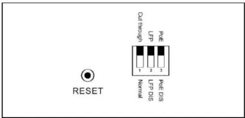
text_image
RESET Cut through LFP PoE - 2 3 Normal LFP DIS PoE DISFig. 15 Reset button and S1—Bit 1, 2, 3 configuration and setting
Reset: Once S1-1, S1-2 is changed, please press this button to have the setting taken effect.
S1-1 Bridge mode: Cut through (default) or Normal
S1-2 LFP: LFP enabled(default) or disabled
S1-3 PoE ON/OFF: Enable(default) or disable
Note:
- S1-1: Cut through mode support jumbo frame size max. up to 9216 Bytes.
Normal mode max. frame size up to 2048 Bytes
- S1-3: Must be set to PoE ON while power supplies to PD.
9. Cable Connection Parameter
1000Base-SX/LX network only support full-duplex mode. The switch-based bridge breaks up TP and fiber segments' collision domain to extend the cabling distance.
- TP Cable Limitations: Cat. 5 and up to 100m
• Bridge Fiber Cable Limitations:
| Mode | Multi-Mode Fiber 62.5/125μm | Multi-Mode Fiber 50/125μm | ||
| Bandwidth MHz-Km | Distance | Bandwidth MHz-Km | Distance | |
| 1000SX (SC/LC)850nm | 160 | 220m | 400 | 500m |
| 200 | 275m | 500 | 550m | |
| 1000LX (SC/LC)1310nm/1550nm | Single-Mode Fiber 9/125μmSingle-Mode transceiver 1310nm: 10KmSingle-Mode transceiver 1550nm: 30/50Km | |||
| Single Fiber Model | TX, RX Wavelength | |
| 1310nm Single-Mode 10Km* 20Km models are option | TX (Transmit) | 1310nm |
| RX (Receive) | 1550nm | |
| 1550nm Single-Mode 10Km* 20Km models are option | TX (Transmit) | 1550nm |
| RX (Receive) | 1310nm | |
Note:
The 1310nm and 1550nm models must be installed in pairs, i.e., install 1310nm model at one end and 1550nm model at the other one.
10. PoE PSE TP-Fiber Technical Specifications
• Standards: IEEE802.3u 10/100Base-TX, 100Base-FX
IEEE802.3z/ab 1000Base-T
IEEE802.3af Power-over-Ethernet
• UTP Cable: Cat. 5 cable and up to100m
• Fiber Cable: 50/125, 62.5/125 or 100/140μm multi-mode
8.3/125, 8.7/125, 9/125 or 10/125μm single-mode
• PSE Power Feeding Supports:
Alternative A via TP pinout 1, 2, 3, 6
Alternative B via TP pinout 4, 5, 7, 8
• LED Indicators:
POWER, PoE, TP LNK/ACT, SPD, FX LNK/ACT, 4W, 7W, 15.4W
• Data Transfer Rate:
| Speed | Forwarding Rate |
| 1000Mbps | 148,8000 PPS |
| 100Mbps | 148,800 PPS |
| 10Mbps | 14,880 PPS |
- Flow Control: IEEE802.3x compliant for full duplex Backpressure flow control for half duplex
• Power Requirement:
AC Line: 100-240V 50-60Hz
• Power Consumption: 65W
- Ambient Temperature: 0 to 40^ C
• Humidity: 5% to 90%
• ×Dimensions: 40(H) 158(W) 133(D) mm
• Complies with FCC Part 15 Class A and CE mark
Note: For connecting this device to router, converter or switch, please refer to the corresponding device's technical manual.
This document in whole or in part may not be duplicated, reproduced, stored or retransmitted without prior written permission of MICROSENS GmbH & Co. KG. All information in this document is provided 'as is' and subject to change without notice. MICROSENS GmbH & Co. KG disclaims any liability for the correctness, completeness or quality of the information provided, fitness for a particular purpose or consecutive damage.
MICROSENS is a trademark of MICROSENS GmbH & Co. KG. Any product names mentioned herein may be trademarks and/or registered trademarks of their respective companies. SH MS40008xH_ACS_MAN_EN_V1.0.3.Docx