Vanguard S3-80 - Ferngesteuertes spielzeug Scorpion - Kostenlose Bedienungsanleitung
Finden Sie kostenlos die Bedienungsanleitung des Geräts Vanguard S3-80 Scorpion als PDF.


| Produkttyp | Elektronischer Geschwindigkeitsregler (ESC) für ferngesteuerte Fahrzeuge |
| Marke | Scorpion |
| Modell | Vanguard S3-80 Super Stock Kit Set |
| Kategorie | Ferngesteuertes Spielzeug |
| Eingangsspannung | 3-14 V (1-3S LiPo) |
| Motorunterstützung | Bürstenlose Motoren (sensorgestützt und sensorlos) |
| Motorbegrenzung | ≥ 8.5T |
| Dauerstrom | 80 A |
| BEC | 3 A / 6 V (True DC-DC) |
| Abmessungen (B x H x T) | 35,0 x 35,0 x 21,0 mm |
| Gewicht | ca. 70 g |
| Funktionen | Programmierbare Einstellungen, Datenspeicher (bis zu 8000 Datensätze), Temperatursensor, Überhitzungsschutz, Firmware-Update |
| Kühlung | Aluminium-Kühlkörper, Lüfter (im Lieferumfang enthalten) |
| Anschlüsse | 2 Hallsensorenanschlüsse (auch für PC), V-Link USB (im Lieferumfang) |
| Lieferumfang | Vanguard Super Booster, V-Link USB-Kabel, Lüfter |
| Wartung | Regelmäßige Reinigung, Lötarbeiten nur bei ausgeschaltetem Gerät |
| Sicherheit | Überstrom-, Überspannungs- und Temperaturschutz |
| Kompatibilität | Geeignet für 1/8 und 1/10 Maßstab On- und Offroad |
| Garantie | 1 Jahr auf Materialfehler (mit Kaufbeleg) |
| Besonderheiten | Werkseitige Voreinstellungen für Scorpion RS-3420 Motor und Wettbewerbsakku |
Häufig gestellte Fragen - Vanguard S3-80 Scorpion
Benutzerfragen zu Vanguard S3-80 Scorpion
0 Frage zu diesem Gerät. Beantworten Sie die, die Sie kennen, oder stellen Sie Ihre eigene.
Eine neue Frage zu diesem Gerät stellen
Laden Sie die Anleitung für Ihr Ferngesteuertes spielzeug kostenlos im PDF-Format! Finden Sie Ihr Handbuch Vanguard S3-80 - Scorpion und nehmen Sie Ihr elektronisches Gerät wieder in die Hand. Auf dieser Seite sind alle Dokumente veröffentlicht, die für die Verwendung Ihres Geräts notwendig sind. Vanguard S3-80 von der Marke Scorpion.
BEDIENUNGSANLEITUNG Vanguard S3-80 Scorpion

Scorpion Power System
www.scorpion-team.com
Scorpion User Guide for
Vanguard S3-Series
53-140 Modify Kit Set
S3-80 Super Stock Kit Set
V4.1
IMPORTANT
Update the ESC firmware to latest version.
Introduction
Thank you for purchasing Scorpion Vanguard Electronic Speed Controller. This ultimate ready to race ESC gives you a powerful range and reliable performance, even in the extreme conditions.
A high power system for RC model can be very dangerous, please read this manual carefully before installing your new ESC.
1.0 Features
• Wide input voltage range 3-14V (15-35 LiPo)
• Sensored and Sensorless brushless motors (BLDC)
• Drive down to 4.5T motor (Scorpion Vanguard S3-140)
• Drive down to 8.5T motor (Scorpion Vanguard S3-80)
• High current, up to 140A continued current, with current protection
(Scorpion Vanguard S3-140 Modify Kit Set)
• High current, up to 80A continued current, with current protection
(Scorpion Vanguard S3-80 Super Stock Kit Set)
• Factory driver suggested setting
(for use with Scorpion RS-3420 motor and Scorpion competition battery pack)
• Profession PC program and Android apps
- Store up to 8,000 data
• Aluminum heat sinks
• Build-in temperature sensor with adjustable temperature protection
• True DC-DC 3A/6V BEC for servo and receiver
- Multiple protection include: over current, over voltage, temperature protection AutoDetect mode
- Motor over temperature protection (for Scorpion RS-3420 motor)
- 2 x hall sensor connectors: each also can be used for PC connection
• Upgradeable Firmware
- Wide range of settings for different race courses
2.0 Specification
| S3-140-Modify | S3-80-Super Stock | |
| Cost / Budget Current, A | 140.0K | 400.0K |
| Motor Type Supported | Standard and Standardless Brushless Motor | Standard and Standardless Brushless Motor |
| Cars Applicable | L/P & 1/10" on road and off road | 1/8" & 1/10" on road and off road |
| Motor Limit | >= 3.57 | >= 8.97 |
| Resistance | 6.000-40cm^2 | 6.000-50cm^2 |
| Voltage Input | 1% to 1Pa | 1% to 1Pa |
| BEC | drySA DC DC | drySA DC DC |
| Footprint | 30.0 mm (N) x 35.0 mm [μl] | 30.0 mm (N) x 35.0 mm [μl] |
| Size (inft. RAM) | 35.0 x 35.0 x 21.0 mm | 35.0 x 35.0 x 21.0 mm |
| Weight | 4kg | 4kg |
| RAN | dry0.2A | dry0.2A |
| External Programming Part Output | ? | ? |
2.1 Vanguard Super Booster
- 470 u/s x 4 = 1880 u/f total
Voltsor: 169
Size: 5mm 0.1×9mm (W) × 15mm 2
Working Temperature: 105 ℃
3.0 Preparation
- Choose a location for the ESC that is close to the motor, but away from the receiver and single cable to prevent radio interference
- If using double-side tape, clean the bottom of the ESC before applying for best result
- Keep the motor wire as short as possible for the best electric current
• Install cooling fan (included)
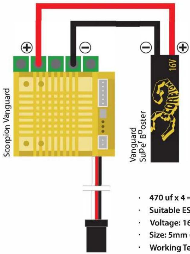
• Install Scorpion Vanguard Super Booster (included), placing the booster as close as
to the ESC, to keep the booster wire as short as possible
- Booster should be mounted directly to the positive (+) and negative (-) on the ESC, as shown in the diagram below
- Keep battery wire as short as possible to crate the best electric current efficiency
4.0 Soldering and Connection
• Always provide a steady working area and easy access to the solder posts
- Do not connect the car battery while working on soldering
- Cut the motor wires to desired length and strip the insulation about 3.2mm-6.35mm from the end. Apply solder to the exposed wire until it is thoroughly covered. **Caution: Solder and iron tip are hot
- Place the iron tip in the notch on top of the post, and then apply small amount of solder to the post
- Hold the tinned wire contact with the notch of the post. Then use the iron tip to heat up the tinned wire and the post for about 2 seconds, allowing the solder to flow. Then remove the iron and hold the wire in position for about 1-2 seconds allowing the solder to set. Caution: do not overheat the ESC
• Refer to the below diagram for proper connection
- Check with battery supplier for the battery connectors (excluded)

text_image
Scorpion Motor Vanguard Super Booster Scorpion Vanguard BATTERY OR Receiver TM5.0 Radio Throttle Calibration
Calibration is necessary for any first use of the ESC. It is also necessary whenever it is used with a new/ different transmitter or when new firmware is updated.
• Make sure the ESC on/off button is "Off"
• Connect the battery, receiver and motor
• Turn on the transmitter
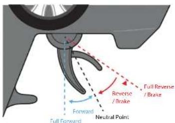
- Move and hold throttle trigger to full reserve/brake
Important: if the full reserve/brake is not held, then the ESC will not activate to calibration mode.
- Press on/off button once to turn on the ESC
- Wait for the first beeping sound (Beep...), then the full reserve/brake will be set
• Pull and hold the throttle trigger to full forward
- Wait for second beep sound (Beep...Beep...), then the full throttle been set
- Hold the throttle trigger in neutral position
- Wait for third beep sound (Beep....Beep.....Beep.....), the neutral been set
- Calibration finish, ESC will restart automatically
text_image
Full Forward Forward Neutral Point Reverse / Brake Full Reverse / Brake6.0 Led & Motor Sound Indication
| ESC turn on | Yellow / Green / Red - On |
| Calibration | Neutral: Red - On / Green & Red - OffFull Reverse / Brake: On / Green & Red - OffFull Forward: Green On / Red & Red - Off |
| Throttle Trigger in Neutral Position | Red - Off if no errors, On if errorsBlinks if zero timing (no boost, no turbo)Off if zero timing, boost, turbo any of these setting is onBattery voltageGreen - On if voltage is OKOff if voltage is lowMotor - ESC over heat - beep...beep...beep..Sound - Motor over heat - beep beep...beep beep...beep beep...ESC & Motor over heat - beep beep...beep beep...beep beep... |
| The motor is running or braking | Red - Off if no errors, On if errorsOnGreen - On if voltage is OK (according to program setting value)Off if voltage is low (according to program setting value) |
| Firmware Update Mode | When ESC in Update Mode - Yellow, Green, Red - OnWhen Updating - Yellow, Green, Red - BlinksUpdate Finish - ESC Ifirstart, Yellow, Green, Red - On. |
| Example of error indication | Conditions - Red LED is ONThrottle in natural position |
| Example - Green LED off- low voltage or cut off (according to program setting value)ESC over heat - beep...beep...beep...Motor over heat - beep beep...beep beep...beep beep...ESC & Motor over heat - beep beep...beep beep...beep beep...Others - Red LED is ON |
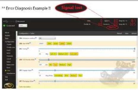
Or connect to PC program locate the problem
text_image
Signal lost ** Error Diagnosis Example !!7.0 Connect ESC to Computer
Team Scorpion provides the most advance setting features or simply download factory driver setting form www.scorpion-team.com
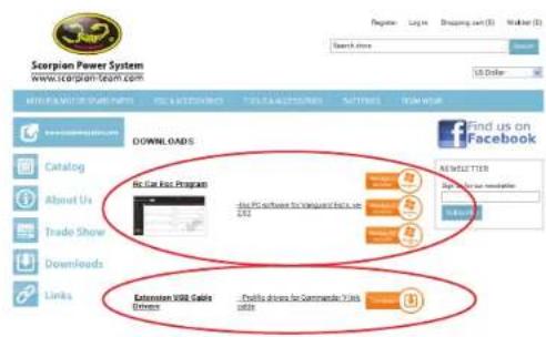
- Download RC Car ESC Program Installer from www.scorpion-team.com, program available for Windows XP, Windows 7, Windows 8 Double click the exe file to start installation
- Download "Extension USB Cable Drivers" from www.scorpion-team.com Double click the "PL2303_Prolific_DriverInstaller_v1.5.0.exe" to install the USB driver If you have any problem installing the USB driver, please read the manual thoroughly or ask an administrator for advice
text_image
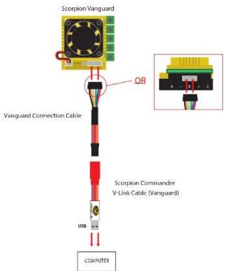
Scorpion Power System www.scorpionteam.com Get us on Facebook Download Catalog About Us Trade Show Downloads Links No Fee Post Program Find PC software for Company's Web 2015 Recommendation Help you use email Send to Enter Station USB Cable Options - Please drive for Commerce Your user- Follow the below diagram to connect the ESC to computer, using the Scorpion V-link USB Cable (included)
text_image
Scorpion Vanguard QR Vanguard Connection Cable Scorpion Commander V-Link Cable (Vanguard) USB COMPUTER• After the connection has been made successfully, the "Connected" display notification and the green light appears
text_image
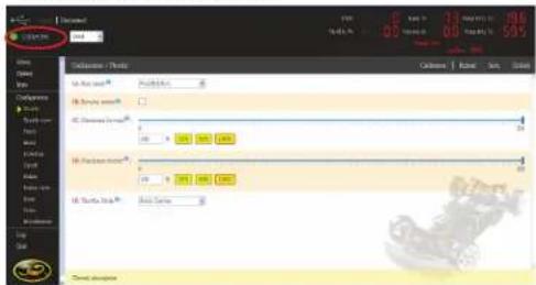
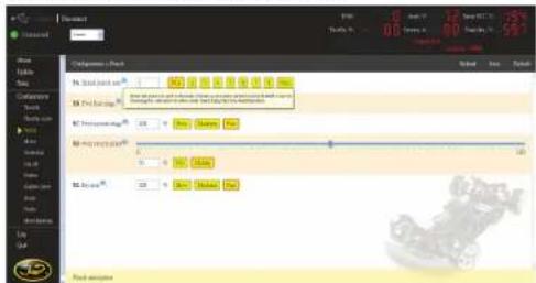
C:\Users\Data\Collected_Check Data List: 100% Data Value: 592 Data Collection: 0.00000000000000000000000000000000000000000000000000000000000000000000000000000000000 Data List: 1.1486 Data Value: 592 Data Collection: 1.1486 Data List: 1.1486 Data Value: 592 Data Collection: 1.1486 Data List: 1.1486 Data Value: 592To know more about each setting description, simply point the mouse cursor to the blue exclamation mark next to the each setting item
text_image
Changgong Book File Edit View Help Book Print (1) Print Print (2) Print Print (3) Print Print (4) Print Print (5) Print Print (6) Print Print (7) Print Print (8) Print Print (9) Print Print (10) Print Print (11) Print Print (12) Print Print (13) Print Print (14) Print Print (15) Print Print (16) Print Print (17) Print Print (18) Print Print (19) Print Print (20) Print Print (21) Print Print (22) Print Print (23) Print Print (24) Print Print (25) Print Print (26) Print Print (27) Print Print (28) Print Print (29) Print Print (30) Print Print (31) Print Print (32) Print Print (33) Print Print (34) Print Print (35) Print Print (36) Print Print (37) Print Print (38) Print Print (39) Print Print (40) Print Print (41) Print Print (42) Print Print (43) Print Print (44) Print Print (45) Print Print (46) Print Print (47) Print Print (48) Print Print (49) Print Print (50) Print Print (51) Print Print (52) Print Print (53) Print Print (54) Print Print (55) Print Print (56) Print Print (57) Print Print (58) Print Print (59) Print Print (60) Print Print (61) Print Print (62) Print Print (63) Print Print (64) Print Print (65) Print Print (66) Print Print (67) Print Print (68) Print Print (69) Print Print (70) Print Print (71) Print Print (72) Print Print (73) Print Print (74) Print Print (75) Print Print (76) Print Print (77) Print Print (78) Print Print (79) Print Print (80) Print Print (81) Print Print (82) Print Print (83) Print Print (84) Print Print (85) Print Print (86) Print Print (87) Print Print (88) Print Print (89) Print Print (90) Print Print (91) Print Print (92) Print Print (93) Print Print (94) Print Print (95) Print Print (96) Print Print (97) Print Print (98) Print Print (99) Print Print (100)8.0 Trouble Shooting
| Trouble Possible Reason Solution | ||
| After powered on, the motor does not rotate and there is no signal light | Poor power connection Check the power connections, replace the connectors if necessary. | |
| After power on, the motor does not spin, but there is signal light | Wrong setting Refer to LED INDICATION to indentify problem | |
| Motor stops halfway | Multiple protection includingOver CurrentOver VoltageLow VoltageTemperature Protection | Refer to LED INDICATION to indentify problem |
| No signs of recognizing from computer program | ESC offCable failurePoor connectionUSB driver | Turn on the ESCChange a new cableCheck all the socketsReplace the Windows ^2 default USB driver with Scorpion provided USB driver |
9.0 Warranty and Service
Scorpion Vanguard Speed Controller is guaranteed to be free from defected materials a dated, itemized sales receipt).
During the warranty period Scorpion will repair speed controller that are found to be defective, providing that it has no signs of damage or abuse. The user will be responsible for shipping charges back to an authorized Scorpion Repair Facility, and Scorpion will pay the return shipping charges. If the damage is the result of a crash or mis-use, the returned item will be repaired, but the cost of repairs will be billed to the user. Repairs will never exceed 50% of the cost of a new speed controller, and if the speed controller is badly damaged or non-repairable, a brand new ESC will be offered at 50% discount of the current retail price for the ESC, plus a nominal shipping charge. If the speed controller returned is no longer in production, Scorpion reserves the right to substitute any other speed controller of equal or better quality. In any event, Scorpion shall not be responsible for the damage that may result from the overuse of products, for consequential or special damages, or for any amount that exceeds the product value. If the motor product is purchased in clearance section, crash and dent section from www.scorpionsystem.com and www.scorpion-team.com, thenthe items are sold "AS IS". No refund or warranty policy will be covered with these products. It is because we do not have parts anymore to repair or replace, or replacement. Please obtain an RMA number by submitting a request by email to our RMA Department support@spihk.com or our distributors for the RMA number before
sending. The RMA process normally takes around 3 - 4 weeks.
RMA form can be found and download from http://www.scorpion-team.com/downloads/
The Power System of Champions!!

text_image
PRECISION SCORPIOM® PERFORMANCEScorpion Power System
www.scorpionsystem.com
User Guide for Vanguard Super Booster
Features:
- Smoother power
- Cooler running speed control
• More punch to brushless system - Small size and light weight
Note:
Installed as close to the ESC as possible.
text_image
Scorpion Vanguard Vanguard Super Boster 16V 470 uf x 4 = Suitable ES Voltage: 16 Size: 5mm Working Te• 470 uf x 4 = 1880 uf total
• Suitable ESC: Vanguard Series
• Voltage: 16V
• Size: 5mm (L) x 9mm (W) x 15mm (H)
• Working Temperature: 105 °C