
TRU812 - Nicht kategorisiert Audac - Kostenlose Bedienungsanleitung
Finden Sie kostenlos die Bedienungsanleitung des Geräts TRU812 Audac als PDF.


Benutzerfragen zu TRU812 Audac
0 Frage zu diesem Gerät. Beantworten Sie die, die Sie kennen, oder stellen Sie Ihre eigene.
Eine neue Frage zu diesem Gerät stellen
Laden Sie die Anleitung für Ihr Nicht kategorisiert kostenlos im PDF-Format! Finden Sie Ihr Handbuch TRU812 - Audac und nehmen Sie Ihr elektronisches Gerät wieder in die Hand. Auf dieser Seite sind alle Dokumente veröffentlicht, die für die Verwendung Ihres Geräts notwendig sind. TRU812 von der Marke Audac.
BEDIENUNGSANLEITUNG TRU812 Audac
TRU Series
User Manual
Index
Introduction 5
Precautions 7
Safety requirements 7
Caution servicing 7
EC Declaration of Conformity 7
Waste of Electrical and Electronic Equipment (WEEE) 8
Caution 8
Chapter 1: Front & rear panel 9
Front panel overview 9
Rear panel overview 9
Front panel description 9
Rear panel description 9
Chapter 2: Connecting 10
Minimum impedance table 10
Example diagram 10
Chapter 3: Additional information 11
Technical specifications 11
Personal notes 12
Introduction
Line Transformer Unit
The TRU series are Line transformer units containing toroidal line transformers, allowing low impedance power amplifiers to be used for powering large public address audio systems with constant voltage levels of 100 Volt, 70 Volt and 50 Volt.
Several models are available differing in the number of channels and/or the output power for each channel. The output power for each channel can differ from 120 Watt to 500 Watt and the number of channels housed in one unit can vary from 4 to 8.
Unlike regular line transformer units, the TRU series have a special internal decoupling network which make them suitable for use in combination with Class–D power amplifiers.
The line transformers are housed in a solid constructed 19" rack mounting housings with a height of 1 or 2 unit. The connections for both in and outputs are performed using reliable Terminal blocks.
Precautions
READ FOLLOWING INSTRUCTIONS FOR YOUR OWN SAFETY
ALWAYS KEEP THESE INSTRUCTIONS. NEVER THROW THEM AWAY
ALWAYS HANDLE THIS UNIT WITH CARE
HEED ALL WARNINGS
FOLLOW ALL INSTRUCTIONS
NEVER EXPOSE THIS EQUIPMENT TO RAIN, MOISTURE, ANY DRIPPING OR SPLASHING LIQUID. AND NEVER PLACE AN OBJECT FILLED WITH LIQUID ON TOP OF THIS DEVICE.
DO NOT INSTALL THIS UNIT NEAR ANY HEAT SOURCES SUCH AS RADIATORS OR OTHER APPARATUS THAT PRODUCE HEAT
DO NOT PLACE THIS UNIT IN ENVIRONMENTS WHICH CONTAIN HIGH LEVELS OF DUST, HEAT, MOISTURE OR VIBRATION
THIS UNIT IS DEVELOPED FOR INDOOR USE ONLY. DO NOT USE IT OUTDOORS
PLACE THE UNIT ON A STABLE BASE OR MOUNT IT IN A STABLE RACK
ONLY USE ATTACHMENTS & ACCESSORIES SPECIFIED BY THE MANUFACTURER

CAUTION - SERVICING
This product contains no user serviceable parts. Refer all servicing to qualified service personnel. Do not perform any servicing (unless you are qualified to)

EC DECLARATION OF CONFORMITY
This product conforms to all the essential requirements and further relevant specifications described in following directives: 2004/108/EC (EMC) and 2006/95/EC (LVD)

WASTE ELECTRICAL AND ELECTRONIC EQUIPMENT (WEEE)
The WEEE marking indicates that this product should not be disposed with regular household waste at the end of its working life. This regulation is created to prevent any possible harm to the environment or human health.
This product is developed and manufactured with high quality materials and components which can be recycled and/or reused. Please dispose this product to your local collection point or recycling centre for electrical and electronic waste. This will make to sure that it will be recycled on an environmentally friendly manner, and will help to protect the environment in which we all live.
CAUTION
The symbols shown are internationally recognized symbols that warn about potential hazards of electrical products. The lightning flash with arrowpoint in an equilateral triangle means that the unit contains dangerous voltages. The exclamation point in an equilateral triangle indicates that it is necessary for the user to refer to the users manual.

text_image
CAUTION RISK OF ELECTRIC SHOCK DO NOT OPENThese symbols warn that there are no user serviceable parts inside the unit. Do not open the unit. Do not attempt to service the unit yourself. Refer all servicing to qualified personnel. Opening the chassis for any reason will void the manufacturer's warranty. Do not get the unit wet. If liquid is spilled on the unit, shut it off immediately and take it to a dealer for service. Disconnect the unit during storms to prevent damage.
Chapter 1
Front & rear panel
Front panel overview

text_image
TRU415 AUDACRear panel overview

text_image
TRU415 AUDAC EUTION IN OF CAN LUT - NOT A (00 MOUT OFF) CH 4 CH 3 CH 2 CH 1Front panel description
The front panel doesn't contain any indicators or controls because of the complete passive function of the devices.
Rear panel description
The rear panel contains all connection facilities. Every channel is provided with a 3-pin input connector and a 4-pin output connector, both performed by Terminal block connectors with locking screws to ensure a reliable connection.
The input connections (wires coming from the amplifier) shall be connected to the 3-pin connector. Depending of the load capabilities of the connected amplifier the connection can be made for 8 Ohm or 4 Ohm.
The output connections (wires going to the loudspeakers) shall be connected to the 4-pin connector. Depending of the desired output voltage the connection can be made for 100 Volt, 70 Volt or 50 Volt.
NOTE
The front and rear panel for the different TRU units may slightly vary depending on the model (different number of channels or different output power). Although, the principle for all the TRU units stay the same and the connections are always performed in the same way. Because of this, drawings for only one single TRU unit is shown above.
Chapter 2
Connecting
The inputs of the TRU unit simply should be connected to the low impedance loudspeaker outputs of a power amplifier. Depending of the output power and the load capabilities of the connected amplifier the connection can be made for 8 Ohm and 4 Ohm.
Due to the internal decoupling network which is internally provided, the TRU units can be connected to Class–D amplifiers, which is unlikely for regular line transformers (or line transformer units).
The loudspeakers shall be connected to the outputs of the TRU units. Depending of the desired output voltage the connection can be made for 100 Volt, 70 Volt or 50 Volt.
NOTE
The total load of the loudspeaker lines should always be verified before connecting, using a real impedance measurement device.
Minimum impedance table
| 100V 70V 50V | |||
| TRU812 | 83.33 Ohm | 41.67 Ohm | 20.83 Ohm |
| TRU415 | 66.67 Ohm | 33.33 Ohm | 16.67 Ohm |
| TRU425 | 40 Ohm | 20 Ohm | 10 Ohm |
| TRU450 | 20 Ohm | 10 Ohm | 5 Ohm |
Example diagram
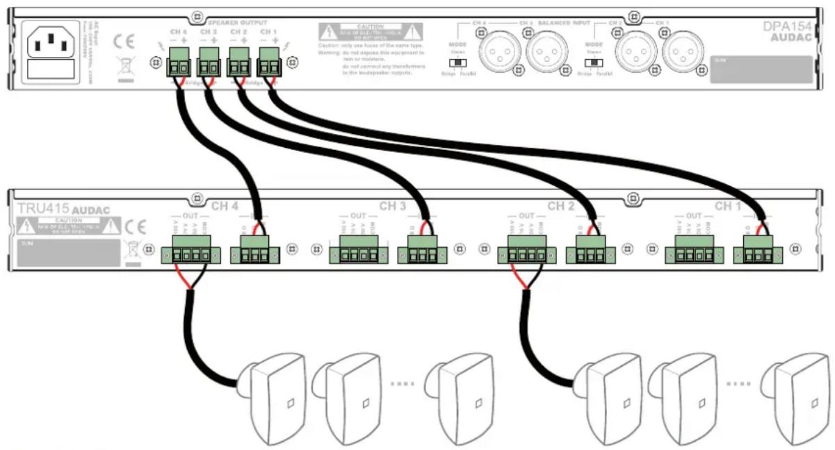
flowchart
graph TD
    subgraph DPA154 AUDAC
        A["Speaker Output"] --> B["CH 4"]
        A --> C["CH 3"]
        A --> D["CH 2"]
        A --> E["CH 1"]
        F["Audio Output"] --> G["OUT"]
        F --> H["OUT"]
        I["Switch"] --> J["Switch Input"]
        K["Switch Output"] --> L["Switch Input"]
        M["Switch Output"] --> N["Switch Output"]
    end

    subgraph TRU415 AUDAC
        O["Switch Input"] --> P["OUT"]
        O --> Q["OUT"]
        R["Switch Output"] --> S["OUT"]
        T["Switch Input"] --> U["Switch Output"]
        V["Switch Output"] --> W["Switch Output"]
    end

    style DPA154 AUDAC fill:#f9f,stroke:#333
    style TRU415 AUDAC fill:#ccf,stroke:#333
Chapter 3
Additional information
Technical specifications
Output power TRU415 4 x 150 Watt
TRU425 4 x 250 Watt
TRU450 4 x 500 Watt
TRU812 8 x 120 Watt
Output power taps 100 Volt / 70 Volt / 50 Volt
Output impedance TRU415 66.67 Ohm / 33.33 Ohm / 16.67 Ohm
TRU425 40 Ohm / 20 Ohm / 10 Ohm
TRU450 20 Ohm/10 Ohm/5 Ohm
TRU812 83.33 Ohm/41.67 Ohm/20.83 Ohm
Input impedance 4 Ohm / 8 Ohm
Frequency response ( ± 3 dB) 35 Hz – 20 kHz
THD+N < 0.1 %
Transformer type Toroidal
Connectors Input 3-pin Terminal block connector with lock (5.08 mm)
Output 4-pin Terminal block connector with lock (5.08 mm)
Construction Steel
Mounting 19 " Rack mount
Unit height TRU415 1 HE
TRU425 1 HE
TRU450 2 HE
TRU812 2 HE
Dimensions (W x H x D) TRU415 482 x 44 x 322 mm
TRU425 482 x 44 x 322 mm
TRU450 482 x 88 x 322 mm
TRU812 482 x 88 x 322 mm
Weight TRU415 Kg
TRU425 Kg
TRU450 Kg
TRU812 Kg
Recommended accessories Procab CLA530 Terminal Block connection cable