ADAM-4520I - Nicht kategorisiert B&B Electronics - Kostenlose Bedienungsanleitung
Finden Sie kostenlos die Bedienungsanleitung des Geräts ADAM-4520I B&B Electronics als PDF.


Benutzerfragen zu ADAM-4520I B&B Electronics
0 Frage zu diesem Gerät. Beantworten Sie die, die Sie kennen, oder stellen Sie Ihre eigene.
Eine neue Frage zu diesem Gerät stellen
Laden Sie die Anleitung für Ihr Nicht kategorisiert kostenlos im PDF-Format! Finden Sie Ihr Handbuch ADAM-4520I - B&B Electronics und nehmen Sie Ihr elektronisches Gerät wieder in die Hand. Auf dieser Seite sind alle Dokumente veröffentlicht, die für die Verwendung Ihres Geräts notwendig sind. ADAM-4520I von der Marke B&B Electronics.
BEDIENUNGSANLEITUNG ADAM-4520I B&B Electronics
ADAM-4510I Robust Isolated RS-422/485 Repeater
ADAM-4520I Robust Isolated RS-232 to RS-422/485 Converter
Packing List
Before you begin installing your module, please make sure that the following materials have been shipped:
1 x ADAM-4510I or ADAM-4520I
1 x DIN-rail mounting bracket (attached)
1 x ADAM-4510I/4520I Startup Manual
1 x Panel mounting bracket
If any of these items are missing/damaged, contact your distributor or sales representative immediately.
CE/FCC Certification
ADAM-4510I and ADAM-4520I developed by Advantech Co., Ltd. has passed the CE and FCC test for environmental specifications. The test conditions for passing including the equipment being operated within an industrial enclosure. Therefore, in order to protect the ADAM module from being damaged by ESD, we strongly recommend that the use of CE-compliant industrial enclosure products.
Overview
Most industrial computer systems come with RS-232 serial ports. Though widely accepted, RS-232 has limited transmission speed, range and networking capabilities. RS-422 and RS-485 standards overcome these limitations by using differential voltage lines for data and control signals.
ADAM-4520I is isolated converter for systems originally equipped with RS-232. It transparently converts RS-232 signals into isolated RS-422 or RS-485 signals. You don't need to change your PC's hardware or your software. The ADAM-4520I lets you easily build an industrial grade, long distance communication system with standard PC hardware.
The ADAM-4510I repeaters simply amplify, or boost, existing RS-485 signals to enable them to cover longer distances. They extend the communication distance by 4000 ft (1200 m) or extend the number of connected nodes by 32.
Notes
For more information on this and other Advantech products, please visit our websites at:
http://www.advantech.com
http://www.advantech.com/eAutomation
For technical support and service:
http://www.advantech.com.tw/eservice
This manual is for ADAM-4510I and ADAM-4520I.
Part No: 2003451010 (1st Ed) May 2006
Industrial Design
Intelligent RS-485 Control
The RS-485 standard supports half-duplex communication. This means that just two wires are needed to both transmit and receive data. Handshaking signals (such as RTS, Request to Send) are normally used to control the direction of the data flow. A special I/O circuit in ADAM-4510I and ADAM-4520I automatically senses the direction of the data flow and switches the transmission direction. No handshaking signals are necessary. So you can build an RS-485 network with just two wires. This RS-485 control is completely transparent to the user. Software written for half-duplex RS-232 can work without modification.
Isolation
ADAM-4510I and ADAM-4520I's opto-isolators provide 3000 VDC isolation to protect the host computer from ground loops and destructive voltage spikes on the RS-485 data lines.
Surge Protection
ADAM-4510I and 4520I offer internal surge protection on their data lines. Internal high speed transient suppressors on each data line protect the modules from dangerous voltages levels or spikes.
Tough Industrial Design
You can power ADAM-4510I and ADAM-4520 with any unregulated power source between +10 and +48 VDC. Their industrial-grade plastic shells can be mounted on a DIN-rail, panel or in a piggy-backed stack. You make signal connections through plug-in screw terminal blocks, guaranteeing easy installation, maintenance and modification.
Features
• Automatic internal RS-485 bus supervision
- No external flow control signals required for RS-485
• Minimum 3000 VDC isolation
- Transient suppression on RS-485 data lines
• Baud rate up to 115.2 kbps
• Networking up to 4000 feet (1200 m)
- Reserved space for termination resistors
- Power and data flow indicator for troubleshooting
• Power requirement: +10 to +48 VDC
- Mounts easily on DIN-rail or panel
Specifications
Common
- Power Requirement: Unregulated +10 to +48 VDC with protection from power reversals
- Case: ABS+PC with captive mounting hardware
- Accessories (Supplied): DIN-rail Mounting Adapter, Panel Mounting Bracket
- Plug-in Screw Terminal Wiring: Accepts AWG 1-#12 to #22 (0.5 to 2.5 mm) wires
- Operating Temperature: -40 85^ C (-40 \~ 185° F)
- Storage Temperature: -40 85^ C (-40 \~ 185° F)
• Humidity: 5 \~ 95%, non-condensing
ADAM-4510I Specifications
• Baud Rate (bps): 1200, 2400, 4800, 9600, 19.2 k, 38.4 k, 57.6 k, 115.2 k and RS-422 (switchable)
• Isolation Voltage: 3000 VDC
- RS-422/RS-485 Interface Connector: Plug-in screw terminal
• Power Consumption: 1.4 W
ADAM-4520I Specifications
- Baud Rate (bps): 1200, 2400, 4800, 9600, 19.2 k, 38.4 k, 57.6 k, 115.2 k, RTS control and RS-422 mode (switchable)
• Isolation Voltage: 3000 VDC
• RS-232 Interface Connector: Female DB-9
• RS-422/RS-485 Interface Connector: Plug-in screw terminal
• Power Consumption: 1.2 W
Switch Settings
Switch Description
DIP switches in the ADAM converter and repeater modules set the data format (number of bits) and baud rate for the ADAM network. You can configure the other modules in the network via software commands. Your program and the PC's serial port should match the settings of the converter and repeater modules.
SW1
Switch 1 controls the data format. Data can be 9, 10, 11 or 12 bits. The factory default is 10 bits: one start bit, eight data bits, no parity bit and one stop bit.
When using the converter in combination with other ADAM modules, do not change the default setting as ADAM modules have a fixed data format of ten data bits. The option of changing to 9, 11 or 12 bits is for use with other modules (other than ADAM modules) that have different data formats. When you change the data format, you will have to change the data format settings on all the other modules in the network.
SW2
Switch 2 sets the baud rate. The options range from 1200 bps to 115.2 kbps. The factory default is 9600 bps. Be aware that when you change the baud rate, you have to change the baud rate for all the connected modules accordingly. If the RS-422 mode is ON, the baud rate doesn't need to be set.
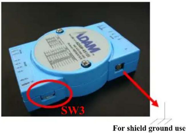
SW3
Switch 3 sets the mode. When the mode is set “Normal”, the baud rate and data format will use SW1 and SW2 setting. When the mode is set “Auto Baud Rate with Noise Reduction”, the baud rate and data format will be set automatically. This mode also help reduce the noise.
Note: There is only one ADAM-4510I or ADAM-4520I module can be set in "Auto Baud Rate with Noise Reduction" mode in single RS-485 network.
Data Format Settings (SW1)
| 9 bits | 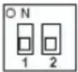 |
| 10 bits (default) | 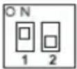 |
| 11 bits | 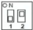 |
| 12 bits | 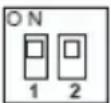 |
ADAM-4510I Repeater Module
| 1200 bps | 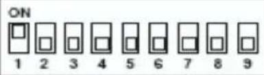 |
| 2400 bps | 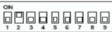 |
| 4800 bps | 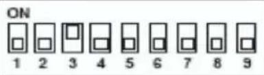 |
| 9600 bps (default) | 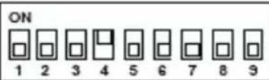 |
| 19.2 kbps | 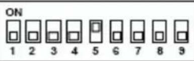 |
| 38.4 kbps | 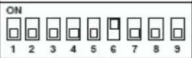 |
| 57.6 kbps | 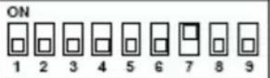 |
| 115.2 kbps /Auto Baud Rate | 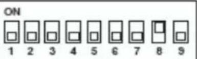 |
| RS-422 | 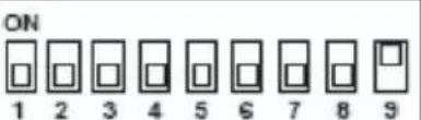 |
ADAM-4520I RS-422/485 Converter Module
| RTS Control | 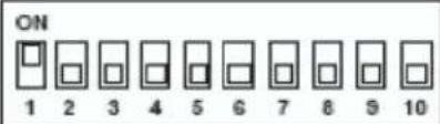 |
| 1200 bps | 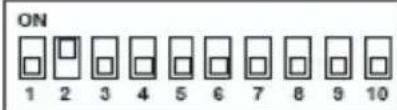 |
| 2400 bps | 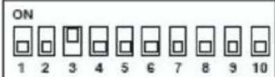 |
| 4800 bps | 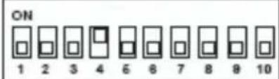 |
| 9600 bps (default) | 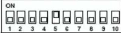 |
| 19.2 kbps | 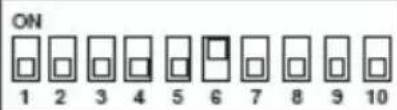 |
| 38.4 kbps | 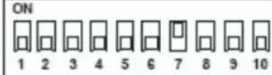 |
| 57.6 kbps | 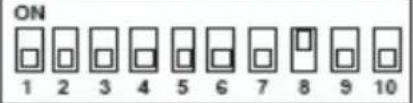 |
| 115.2 kbps/ Auto Baud Rate | 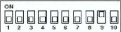 |
| RS-422 | 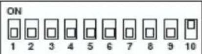 |
Mode Settings (SW3)
| Normal (default) | 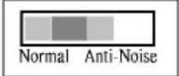 |
| Auto Baud Rate with Noise Reduction | Normal Anti-Noise |
Note: Refer to the image below for the location of SW3
text_image
SW3 For shield ground useCommunication Status
There is one LED on the panel of ADAM-4510I and ADAM-4520I module. Its purpose is to show the communication status:
| Communication Status LED Color | ||
| RS-485 | Idle green | |
| RS-232 → RS-485 flash (green) | ||
| RS-485 → RS-232 flash (red) | ||
| RS-422 | Idle dark green | |
| RS-232 → RS-422 flash (green) | ||
| RS-422 → RS-232 flash (red) | ||
Application Wiring
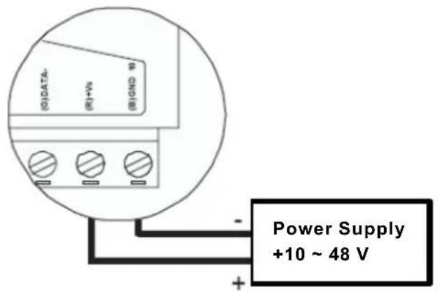
Power Supply
For easy use in industrial environments, the ADAM modules are designed to accept industry standard +24 VDC unregulated power. Operation is guaranteed when using any power supply between +10 and +48 VDC. Power ripples must be limited to 5 V peak to peak while the voltage in all cases must be maintained between +10 and +48 VDC. All power supply specifications are referenced at module connector.
The power cables should be selected according to the number of modules connected and the length of the power lines. When using a network with long cables, we advise the use of thicker wire to limit the line voltage drop. In addition to serious voltage drops, long voltage lines can also cause interference with communication wires.
text_image
(G)DATA- (R)+Vs (B)GND 9 Power Supply +10 ~ 48 VWe advise that the following standard colors (As indicated on the modules) be used for power lines: +Vs (R) Red GND (B) Black
Communication Wiring
We recommend that shielded-twisted-pair cables that comply with the EIA RS-485 standard be used with the ADAM network to reduce interference. Only one set of twisted-pair cables is required to transmit both data and RTS signals. We advise that the following standard colors (as indicated on the modules) be used for the communication lines:
DATA + (Y) Yellow
DATA - (G) Green
Basic Configuration
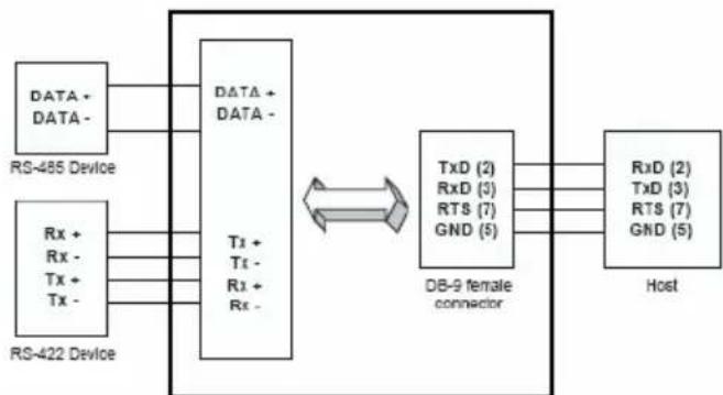
Before placing a module in an existing network, the module should be properly configured. The two following diagrams show typical layouts for both modules:
flowchart
graph LR
    A["DATA + DATA -"] --> B["DATA + DATA -"]
    C["RS-485 Device"] --> B
    D["RS-422 Device"] --> B
    B --> E["TxD (2) RxD (3) RTS (7) GND (5)"]
    E --> F["DB-9 female connector"]
    F --> G["RxD (2) TxD (3) RTS (7) GND (5)"]
    H["Host"] --> F
    B <--> I["双向箭头"]
    D <--> I
ADAM-4520I Converter Module

flowchart
graph LR
    A["DATA + DATA -"] --> B["RS-485 Device"]
    C["Tx + Tx - Rx + Rx -"] --> D["RD-422 Host"]
    E["DATA0 + DATA0 -"] --> F["RS-485 Device"]
    G["Rx 0+ Rx 0- Tx 0+ Tx 0-"] --> H["RD-422 Host"]
    I["DATA1 + DATA1 -"] --> J["RS-485 Device"]
    K["Tx 1+ Tx 1- Rx 1+ Rx 1-"] --> L["RD-422 Slave"]
    M["Rx + Rx - Tx + Tx -"] --> N["RD-422 Slave"]
    B <--> F
    F <--> J
ADAM-4510I Repeater Module
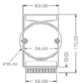
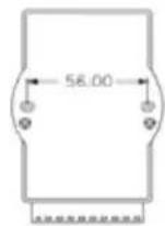
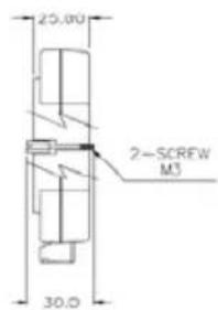
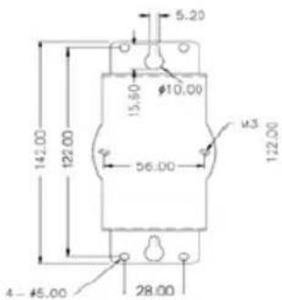
ADAM Dimensions
text_image
60.00 56.00 235.00 52.00 112.00 10.0FRONT VIEW
REAR VIEW
text_image
20.00 2-SCREW M3 30.0SIDE VIEW
text_image
5.20 15.50 Ø10.00 141.00 122.00 56.00 Ø3 122.00 4 - Ø5.00 28.00PANEL MOUNTING BRACKET
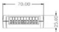
TOP VIEW
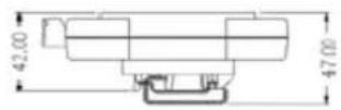
DIN - RAIL MOUNTING
ADAPTER
Function Diagrams
ADAM-4510I Repeater
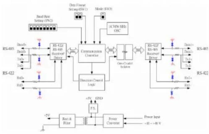
flowchart
graph TD
    A["RS-422"] --> B["RS-423"]
    B --> C["RS-485"]
    C --> D["RS-422"]
    D --> E["RS-423 Receiver/Delay"]
    E --> F["Communication Channel"]
    F --> G["Directional Control Logic"]
    G --> H["One-Count Isolation"]
    H --> I["RS-423 Receiver/Delay"]
    I --> J["RS-485"]
    J --> K["RS-422"]
    K --> L["RS-423 Receiver/Delay"]
    L --> M["Power Converter"]
    M --> N["+5V Gain"]
    N --> O["RS-422"]
    O --> P["RS-485"]
    P --> Q["RS-422"]
    Q --> R["+5V Input +H → -R V"]
    R --> S["Power Input"]
    S --> T["+5V Gain"]
    T --> U["RS-422 Receiver/Delay"]
    U --> V["RS-485 Receiver/Delay"]
    V --> W["Data Format Setting (SW1)"]
    W --> X["Mode (SW3)"]
    X --> Y["14.74% MHz OSC"]
    Y --> Z["Serial Rate Setting (SW2)"]
    Z --> AA["Data Flow Setting (SW1)"]
    AA --> AB["RS-422 Receiver/Delay"]
    AB --> AC["RS-485 Receiver/Delay"]
    AC --> AD["Data Flow Setting (SW1)"]
    AD --> AE["RS-422 Receiver/Delay"]
    AE --> AF["RS-485 Receiver/Delay"]
    AF --> AG["Data Flow Setting (SW1)"]
    AG --> AH["RS-422 Receiver/Delay"]
    AH --> AI["RS-485 Receiver/Delay"]
ADAM-4520I Converter
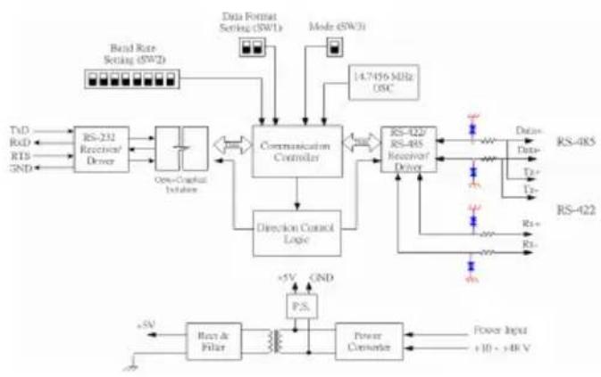
flowchart
graph TD
    A["Input"] --> B["RS-231 Receiver/ Driver"]
    B --> C["One-Channel Isolation"]
    C --> D["Communication Controller"]
    D --> E["RS-422/RS-RS Receiver/ Driver"]
    E --> F["Data Input"]
    E --> G["Data Output"]
    E --> H["RS-485"]
    E --> I["RS-422"]
    J["Data Format Setting (SWI)"] --> D
    K["Mode (SWCI)"] --> D
    L["Band Rate Setting (SWI)"] --> D
    M["TaD"] --> B
    N["RxD"] --> B
    O["RTB"] --> B
    P["GND"] --> B
    Q["+5V"] --> R["Power Converter"]
    S["CND"] --> R
    T["P.S."] --> R
    U["+10 < +8V"] --> R
    V["14.7456 MHz USC"] --> D