AV-1 - Fahrradcomputer Avenir - Kostenlose Bedienungsanleitung
Finden Sie kostenlos die Bedienungsanleitung des Geräts AV-1 Avenir als PDF.


Benutzerfragen zu AV-1 Avenir
0 Frage zu diesem Gerät. Beantworten Sie die, die Sie kennen, oder stellen Sie Ihre eigene.
Eine neue Frage zu diesem Gerät stellen
Laden Sie die Anleitung für Ihr Fahrradcomputer kostenlos im PDF-Format! Finden Sie Ihr Handbuch AV-1 - Avenir und nehmen Sie Ihr elektronisches Gerät wieder in die Hand. Auf dieser Seite sind alle Dokumente veröffentlicht, die für die Verwendung Ihres Geräts notwendig sind. AV-1 von der Marke Avenir.
BEDIENUNGSANLEITUNG AV-1 Avenir
Diamond Back, Cenituron and Avenir products are designed by WSL. © WSL California.
(1)
Avenir AV-1 Owner's Manual
lead all directors carefully before using your Avens AV-1.

Precautions
- Do not preoccupy yourself with watching the computer while riding. Pay attention to traffic and road conditions.
- Do not leave the main unit in direct sunlight when not in use.
- If the Main Unit will not be used for extended periods, remove the battery.
Avenir AV-1 Installation Instructions
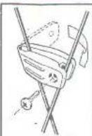
Mounting the Wheel Magnet: Attach the Wheel Magnet by whipping it around the spokes on the right hand side of the front wheel as shown in Figure 1. Secure with screw provides
Figure 1
Mounting the Wheel Sensor Unit: Attach the Wheel Sensor Unit to the right backblade of the bicycle as shown in Figure 2. Use the Rubber Friction Pad to ensure that the unit grips the fontblade securely
Figure 2

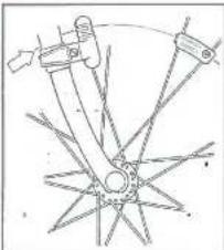
Alignment of the Wheel Sensor Unit: The Wheel Sensor Unit and the Wheel Magnet must be aligned as shown in Figure 3 in order to function properly. When the Wheel Magnet passes the Wheel Sensor Unit, there should be no more than a 1mm gap
Figure 3
natural_image
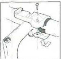
Pure mechanical linkage diagram without any text, numbers, or symbolsMounting the Handlebar Bracket: Using the 1mm or 5mm thick pads to ensure proper fit attach the bracket on the right hand side of the stem so that the mounting channels for the man unit are located directly above the stem as shown in Figure 4. If the stem does not provide enough clearance for the mounting bracket, slide the bracket further to the right
Figure 4
natural_image
Line drawing of a mechanical component with a handle and bracket (no text or symbols)Securing the Wire:
Using the wire clips provided, secure the wire between the white. Sensor unit and the Handlebar Mounting Brackets. Stop the wire to the folklade and to the head, none of the bicycle. Make sure there is enough stock on the wire to allow the handlebars to rotate ready to both sides. Use keys (or similar tool) to pull bed the wire clips. Trim the excess part of the clipp with wire clips or heavy duty scissors.
Mounting the Main Unit:
Starting with the man unit in front of the Handlebar Mounting Bracket, a gate the mounting channels with the corresponding channels on the main unit. Slide the man unit back until a click is in place.
Main Unit Preparation
Before operating your computer the following steps must be complained
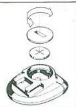
Installing the Battery: Turn the main unit over: Using a coin (or similar object) remove the battery cover by twailing it counter-clockwise, Insect the included CR203 with battery, making sure that the positive (+) pole is facing upwards. Once the battery is in place, replace the battery cover securely (Figure 5).
Figure 5
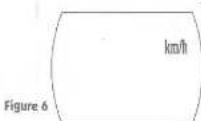
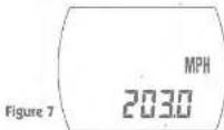
Setting the Unit for Miles or Kilometers: Press and hold down the Mode and Set buttons simultaneously for 6 seconds. The display will clear, except for the KWH/MPH indicator. The unit is preset for kilometers (Figure 6). To switch to miles, press the Set button once. The indicator on the display will change to MPH. Once the desired setting has appeared on the display, press the Mode button once. The display will change to show the wheel circumference indicator (80.0) across the bottom of the screen (Figure 7).
Setting the Wheel Circumference:
The unit is preset for the die preference of a standard ATB wheel (80.5 inches). If you need to revise this number, refer to the following Chad to determine the proper cue preference
Wheel Chart
| Wheat Diameter | circularumference | Indice | |
| Inches | conclusions | ||
| 20 | 51 | 139.6 | |
| 19.95 | 52 | 144.0 | |
| 19.5 | 57 | 163.0 | |
| 19.75 | 53 | 165.6 | |
| 21 | 93 | 167.6 | |
| 19.95 | 54 | 169.6 | |
| 21.5 | 55 | 171.0 | |
| 19.75 | 35 | 173.6 | |
| 19 | 36 | 175.5 | |
| 19.95 | 57 | 177.5 | |
| 22.5 | 57 | 179.5 | |
| 20.75 | 58 | 181.5 | |
| 19 | 38 | 183.3 | |
| 19.95 | 39 | 185.3 | |
| 23.5 | 60 | 187.5 | ATB 24 x 1.75 |
| 23.75 | 60 | 189.0 | |
| 34 | 51 | 191.5 | |
| 24.25 | 62 | 193.5 | |
| 24.3 | 62 | 195.5 | |
| 14.75 | 63 | 197.5 | |
| 25 | 64 | 199.5 | ATB 20 x 1.4 |
| 19.25 | 64 | 201.5 | |
| 19.3 | 65 | 203.5 | ATB 20 x 1.5 |
| 19.75 | 65 | 205.5 | ATB 30 x 1.75 |
| 56 | 66 | 207.5 | 650 A |
| 19.65 | 67 | 209.5 | 700 x 85 C |
| 19.5 | 67 | 211.5 | Trina 4A |
| 19.75 | 68 | 213.4 | 700 x 85 C |
| 27 | 69 | 215.4 | 700 x 70 C |
| 27.85 | 69 | 217.4 | |
| 27.5 | 70 | 219.4 | |
| 19.75 | 70 | 221.4 | |
| 29 | 71 | 223.4 | 700 B |
| 19.95 | 72 | 225.4 | |
| 18.5 | 73 | 227.4 | |
| 19.75 | 73 | 229.4 | |
If your wheel size is not included in the chest, and you wish to determine the setting with the highest degree of accuracy, calculate the circumference of your wheel as follows:
Please your bicycle on a flat surface and rotate the front wheel until the valve stem is at the bottom. Mark the spot. Roll your bicycle in a straight line until the wheel has completed one full revolution. Mark the spot as well. Measure the distance between the two miles in centimeters for ten inches and then multiply by 9.541.
Enter the wheel circumference into the main unit using the Set button. Pressing the Set button once advances the setting by 0.1. Holding the Set button down will rapidly advance the setting. Once the desired number is destroyed press the Mode button. The display will change, so the current (me indication) across the button of the screen (19:00:00).
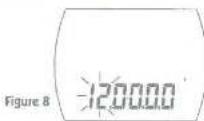
Setting the Current-Time: When the current time and color is first selected, the hours digit will flash (Figure 8). To set the correct time press the Set button until the proper hour is displayed. Once the hour is correct press the Mouse button on line. The hours digit will stop flashing and the minutes digit will enter. Use the Set button to advance the minutes indicator until the current minute is displayed (by pressing the Set button continuously the minutes indicator will advance rapidly). Once the minutes digit is correct, press the Mouse button. The second digits will flash press the Set button. The second digits will change to zero. Press the Mouse button. The men unit it now ready to use.
Operating Functions
The computer is reset every time the Mode and Set buttons are held down simultaneously. Resetting the computer will clear all functions except for the Total Distance Odometer and Current Time.
The function display is changed by pressing the mode button once.
An auto-hold function will suspend the Average Speed and Blessed time calculations if the bicycle remains stationary for more than seven (7 seconds). Due to all functions will be held in memory. When the auto-hold function is enabled, the mode button can be used to review the status of all of the functions. The auto-hold function is cancelled once the bicycle is mentioned
Current Speed:
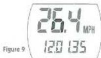
The Current Speed is displayed continuously on the top line of the display (Figure 9). Current Speed will display even when the Sat button has not been pressed. Current Speed is updated at one second intervals.
(AVS) Average Speed:
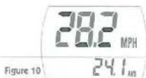
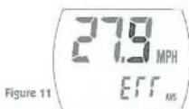
Average Speed is calculated on the basis of the elapsed time and the trip distance. Average Speed is calculated to 0.1 MPa (0.1 Km/h). Average Speed will be calculated for trips lasting up to 24 hours or 1000 miles (kilometers) (Figure 10). Figure 11 shows error reaching if 24 hour period is exceeded.
(MAX) Maximum Speed:
Max/min Speed is speed in memory until the unit is reset. The compute will accurately be -1 MPH or Kinht record speeds up to 50 MPH (50 Kinht). Above the speed accuracy will gradually decline (Figure 12).

(ETM) Elapsed Time:
Elapsed Time function operates only when the wheel rotates. The computer will display time in HHMM-SS format for trips taking up to 24 hours. After 24 hours the elapsed time will roll over to zero and continue from there (Figure 13)
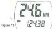
(TRP) Trip Odometer:
The Trip Odometer measures the distance leveled since the time of the last test. Distances are measured in 0.1 mile (0.1 kilometer) increments. When 1,000 miles (1,000 kilometers) are reached, the Trip Odometer returns to zero and counting continues (Figure 14).
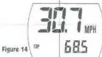
(ODO) Total Distance Odometer:
Average is continuously measured, accumulated and displayed until the battery wears down (Figure 15). Distance is measured in 0.1 mile (0.1 kilometer) increments. When 10,000 miles (10,000 kilometers) are reached, the Total Distance Odometer returns to zero and counting begins anew
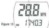
Clock/Current Time:
The current is displayed in HH/MN,35 (cm)
Troubleshooting
- Problem- The liquid crystal display is unusually dry and the digits are difficult to read
Solution- This oogars when the display has been left in direct sunlight too long. The display will return to normal once it has been placed on the shade for a few minutes. Data will not be adversely affected when the oogars
- Problem- Display response is slow.
Solution- Cold temperatures (under 39 degrees) will slow the response of the liquid crystals in the display. Once the temperature uses above freezing the display response will return to normal.
- Problem-No display
Solution- Check the battery. Replace with C19032 lithium battery as outlined in the owner's manual.
- Problem- Conheed or incorrect data appears on the display
Solution- Perform the Main Unit preparation sequence outlined in the owners' manual.
- Problem- Current Speed does not appear in the display
Solution: Check to see that the Main Unit is securely mounted on the Handelser Mounting Bracket. Make sure the leads on the bottom of the Main Unit and top of the Handelser Mounting Bracket are both clear and dry. Check the argument of the Wheel Magnet and the Wheel Sensor Unit. Make sure there a range more than a Term gap between the two when the Wheel Magnet passes the Wheel Sensor Unit. Check the argument of the Wheel Magnet and the Wheel Sensor Unit.

All Avenir Cycle Computer products are manufactured to the highest standards of quality. This cycle computer is warranted to be free from defects in workmanship and materials for a period of one year from the date of purchase. Should the cycle computer fail under normal use please return it to your Avenir dealer along with proof of purchase for inspection. It will be replaced without charge to you (except for freight to and from your Avenir dealer) if it is determined to be defective in workmanship or materials.
The following conditions apply to the warranty: 1. The warranty becomes void if the cycle computer shows evidence of (a) use other than that for which it was designed, (b) damage resulting from attempted repairs or disassembly, (c) improper storage/safekeeping, (d) impacts received during accidents, (e) damage resulting from fire, earthquake or other acts of God and (f) damage or wear resulting from normal use.
- Batteries are not covered by this warranty.