5002 - Heimtrainer SportsArt - Kostenlose Bedienungsanleitung
Finden Sie kostenlos die Bedienungsanleitung des Geräts 5002 SportsArt als PDF.


| Produkttyp | Heimtrainer |
| Marke | SportsArt |
| Modell | 5002 |
| Abmessungen (L x B x H) | ca. 100 x 50 x 120 cm |
| Gewicht | ca. 30 kg |
| Maximales Benutzergewicht | 120 kg |
| Stromversorgung | Batterien (2 x AAA, nicht im Lieferumfang) |
| Widerstandssystem | Magnetbremssystem, manuell einstellbar |
| Widerstandsstufen | 8 Stufen |
| Display | LCD mit Zeit, Distanz, Geschwindigkeit, Kalorien, Puls (Handpulssensoren) |
| Sitzverstellung | Höhenverstellbar (mehrere Positionen) |
| Lenker | Verstellbar, mit Pulsmessung |
| Pedale | Mit Riemen und rutschfester Oberfläche |
| Transportrollen | Ja, für einfaches Bewegen |
| Bodenausgleich | Verstellbare Gummifüße |
| Reinigung | Mit leicht feuchtem Tuch abwischen; keine aggressiven Reiniger |
| Wartung | Regelmäßig Schrauben nachziehen, bewegliche Teile ölen |
| Sicherheitshinweise | Nicht von Kindern unter 14 Jahren ohne Aufsicht nutzen; nur für den Hausgebrauch |
| Ersatzteile | Über den Kundendienst von SportsArt erhältlich |
| Garantie | 2 Jahre |
| Lieferumfang | Heimtrainer, Montagematerial, Bedienungsanleitung |
Häufig gestellte Fragen - 5002 SportsArt
Benutzerfragen zu 5002 SportsArt
0 Frage zu diesem Gerät. Beantworten Sie die, die Sie kennen, oder stellen Sie Ihre eigene.
Eine neue Frage zu diesem Gerät stellen
Laden Sie die Anleitung für Ihr Heimtrainer kostenlos im PDF-Format! Finden Sie Ihr Handbuch 5002 - SportsArt und nehmen Sie Ihr elektronisches Gerät wieder in die Hand. Auf dieser Seite sind alle Dokumente veröffentlicht, die für die Verwendung Ihres Geräts notwendig sind. 5002 von der Marke SportsArt.
BEDIENUNGSANLEITUNG 5002 SportsArt
SPORTS ART COMMERCIAL GRADE 5002 GENERATOR SEMI-RECUMBENT CYCLE
SAFETY GUIDELINES:
Please read and follow the following safety guidelines:
. Read this owner's manual and follow the instructions.
. Assemble and operate the cycle on a solid, level surface.
. Never allow children on or near the cycle.
. Check the cycle before every use. Make sure all parts are assembled, and all nuts and bolts are tightened. Do not use the cycle if the unit is disassembled in any way.
. Keep your hands away from moving parts.
. Wear proper workout clothing: do NOT wear loose clothing. Do not wear shoes with leather soles or high heels. Tie all long hair back.
. Don't rock the unit from side to side, and use care when mounting and dismounting the unit.
. Don't stand on the unit.
. Do not use any accessories that aren't specifically recommended by the manufacture as these might cause injuries or cause the unit to fail.
. Work within your recommended exercise level--do NOT work to exhaustion.
. If you feel any pain or abnormal sensations, STOP YOUR WORKOUT and consult your physician immediately.
Caution:
Before beginning any exercise program, you should consult with your doctor. It is recommended that you undergo a complete physical examination.
INTRODUCTION
Congratulations on purchasing one of the finest pieces of commercial grade exercise equipment on the market today, the Sports Art 5002. Constructed of high quality materials and designed for years of trouble free usage, the 5002 will be an integral part of your fitness regimen.
Before using your cycle, we recommend that you familiarize yourself with this Owner's Manual. Whether you are a first time user of an exercise bicycle or a seasoned "pro," understanding the correct use of the equipment will enhance your ability to achieve your exercise goals safely and successfully.
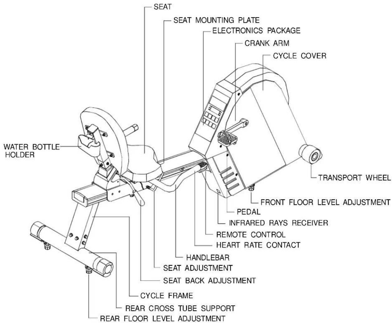
text_image
WATER BOTTLE HOLDER SEAT SEAT MOUNTING PLATE ELECTRONICS PACKAGE CRANK ARM CYCLE COVER TRANSPORT WHEEL FRONT FLOOR LEVEL ADJUSTMENT PEDAL INFRARED RAYS RECEIVER REMOTE CONTROL HEART RATE CONTACT HANDLEBAR SEAT ADJUSTMENT SEAT BACK ADJUSTMENT CYCLE FRAME REAR CROSS TUBE SUPPORT REAR FLOOR LEVEL ADJUSTMENTASSEMBLING YOUR CYCLE
List Of Parts:
. Six 5/16"x 3/4" bolts - Rear cross tube support
. Six 5/16" Spring washers - Rear cross tube support
. Six 5/16" washers - Rear cross tube support
. Four 5/16"x 3/4" bolts - Handlebar mounting plate
. Four 5/16" Spring washers - handlebar mounting plate
. Four 5/16" washers - handlebar mounting plate
. Four 5/16"x 3/4" bolts - Seat
. Four 5/16 flat washers - Seat
. One pair of foot pedals
. One set of screw drivers
. One hex allen wrench
. One combination wrench
. Two fuses - 3 amp for battery
3 amp for generator system
Step By Step Instructions:
Before assembling your cycle, make sure that you have all the above parts.
The following steps explain how to assemble your 5002. Please read every step thoroughly, and follow the directions completely to ensure correct assembly.
-
Make sure all packing materials are removed from the cycle frame.
-
Place the cycle on a level, flat surface.
-
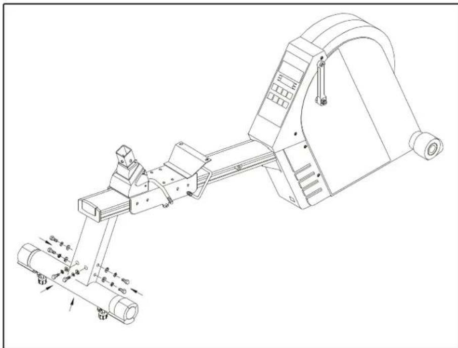
Place the end of the cycle frame over the rear cross tube supports. Attach the cycle frame to the rear cross tube support using two bolts, two spring washers and two flat washers on each side. Make sure that the front and rear legs sit flat on the floor before tightening the bolts securely (see Fig. 1).
natural_image
Technical line drawing of a mechanical assembly with rollers and a conveyor belt (no text or symbols)(FIG.1)
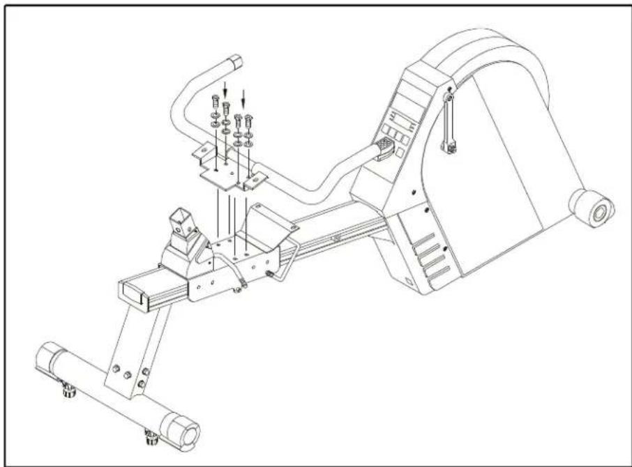
- Attach the handlebar mounting plate to the cycle frame, using four bolts, four spring washers and four flat washers. Tighten the four bolts securely (see Fig. 2).
natural_image
Technical line drawing of a mechanical assembly with no visible text or symbols(FIG.2)
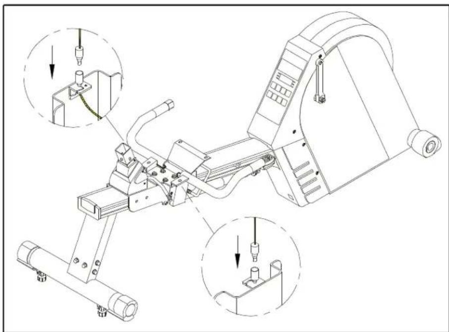
- If your cycle is equipped with Hand Touch Readout, please connect two wires to the sockets located on the cycle frame. (see Fig.3).
natural_image
Technical line drawing of a mechanical assembly with three views of a device (no text or symbols present)(FIG.3)
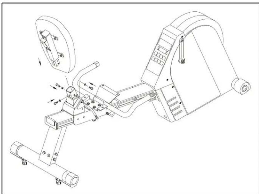
- Insert the post of seat back into the mounting plate and tighten securely using the screws and washers provided (see Fig. 4).
natural_image
Technical line drawing of a mechanical exercise machine with no visible text or symbols(FIG.4)
Attach the seat base to the handlebar mounting plate, using the screws and washers provided. Insert the screws from underneath the seat--two in back and two in front, through the handle bar mounting plate. Tighten the screws securely (see Fig.5).

natural_image
Technical line drawing of a mechanical assembly with no visible text or symbols(FIG.5)
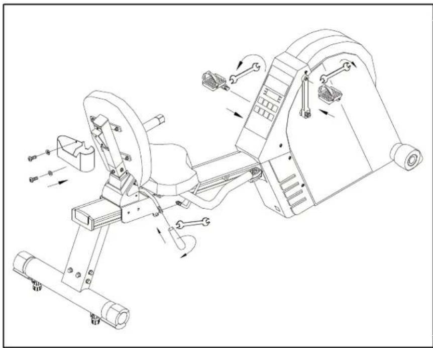
Attach the seat back adjustment handgrip to the seat back adjustment lever, using the wrench provided. Also attach the water bottle/personal stereo holder to the back of the seat, using the screws and washers provided (see Fig.6).
natural_image
Technical line drawing of a mechanical exercise machine with no visible text or symbols(FIG.6)
Attach the foot pedals to the crank arms on the cycle using the wrench provided. Be careful to install the pedals on the correct crank arm. A"R" or "L" on the foot pedal indicates the correct side. Install the pedal marked "R" on the right-hand crank arm (as you stand at the rear of the cycle facing front). When you install the pedal on the left hand crank arm, rotate the pedal counterclockwise to tighten since the pedal has lift-hand screw threads (see Fig 6). Tighten the pedals securely.
Floor Level Adjustment
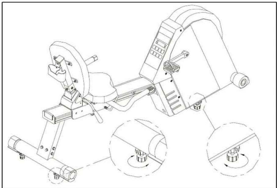
If the cycle is unsteady on your floor, turn the floor level adjustment either on the rear feet or front of cycle. Raise or lower the floor level adjustment to steady your cycle (see Fig. 7).
natural_image
Technical line drawing of a mechanical exercise machine with three circular insets showing rotational components (no text or labels)(FIG.7)
text_image
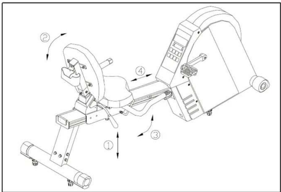
Technical diagram of a stationary exercise machine with numbered components and directional arrows indicating motion.(FIG.8)
Seat Adjustment
Before your workout, you might need to adjust the seat to the appropriate position for your back or leg length. Sit on the cycle with both feet in the pedals and one leg extended as far as possible, pull up on the seat adjustment lever, and move the seat forward and backward until the pedal distance is comfortable. Release the seat adjustment lever (see Fig.8).
The 5002 is equipped with a two piece seat, allowing you to adjust the seat back's angle of incline. Pull on the seat back adjustment lever and move the seat up and back to find the most comfortable position for you, then release the lever (see Fig.8).
Your 5002 Semi-Recumbent Cycle is assembled and ready to use.
EXERCISING ON YOUR CYCLE
Using The Handle Bar Remote Control:
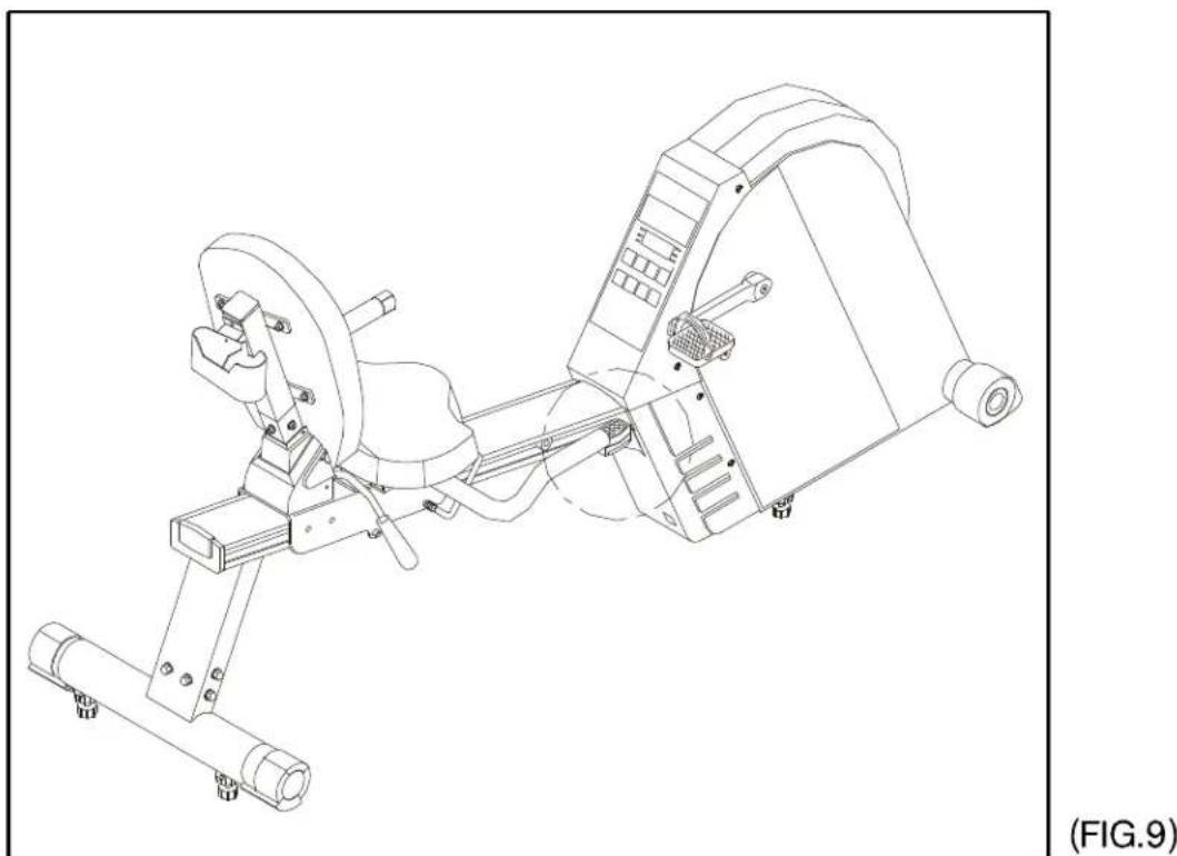
For your convenience while exercising, the 5002 comes with a unique remote control at the end of right handlebar. It's quicker and easier than ever to enjoy your workout. The keep on the remote function exactly like the keep on the electronics package (see Fig. 9).
natural_image
Technical line drawing of a stationary exercise machine (no text or symbols present)Understanding The Electronics Package
Unlike other generator cycles, where you have to pedal for the unit to start, with the Sports Art 5002, you only have to press the "ON" key to program the unit. This is much easier to accomplish, rather than having to pedal and enter information at the same time.
MANUAL:
- Press the Electronics Package "ON" key to start. The cycle will enter the MANUAL MODE immediately.
- If you do not change the MODE or choose a LEVEL (or WATTS), the display will prompt you to PEDAL TO START. The cycle will remain in the MANUAL MODE. If you do not pedal for over 2 minutes, the electronics package will switch OFF automatically.
- If you stop in the middle of your workout, you will be prompted to PEDAL TO START. All input information (DIST., CAL., TIME, etc.) will be retained.
- You can use the MODE button to switch to LEVEL (or WATTS), TIME, DISTANCE, RPM, CAL., SCAN or PULSE. Use the ▲▼ keys to set the desired LEVEL (or WATTS), TIME or DISTANCE.
MODE (What each of these categories means):
LEVEL: There are 14 levels, with Level 1 being the lightest, and LEVEL 14 being the heaviest. Use the ▲▼ keys to choose the desired level.
WATTS: The watts range from 50-320 watts, with the 50 being the lightest, and 320 being the heaviest. Use the ▲▼ keys to chose the desired watts.
TIME: Use the ▲▼ keys to set the desired time. The electronics package will beep for 1.5 seconds when your desired time is reached, then will start to count up if your workout continues.
DIST.: Use the ▲▼ keys to set the desired distance. Each press of the keys changes the distance by 0.05 miles (0.1 km). If you hold down the keys, the numbers will increase or decrease by 0.5 miles or 1 km every 5 seconds.
RPM: A sensor counts the number of revolutions the flywheel makes in one minute, and this is displayed on the screen.
CAL.: This readout gives you the amount of calories burned, based on the weight entered and speed/distance cycled.
SCAN: Pressing the MODE key to "SCAN" mode, will result in the display alternating between Mode readouts every 4 seconds.
SET:
Press the MANUAL/SET key, and "MAN'L" will show in the display. Press the key once again, and "SET" will appear in the display. Press ENTER.
-
You can choose between MILE/KILO, WEIGHT and MALE/FEMALE while in the SET MODE.
-
The read out will display "PRESS ▲▼ TO SELECT MILE/KILO". Press ▲▼ keys to select either MILE or KILO, then press ENTER to save your selection. (Note: choosing MILE will automatically select pounds in the weight calculation, and choosing KILO will automatically select kilograms in the weight calculation.)
-
You will be prompted to choose between "MALE / FEMALE". Use the ▲▼ to select your choice, then press ENTER to record that choice.
-
Next, "PRESS ▲▼ TO INPUT WEIGHT" will scroll across the screen. Then the last weight setting will show on the display. Use the ▲▼ keys to change your desired weight.
Once you have set the desired weight, press "ENTER" to record them. This will allow the unit to calculate caloric expenditure.
Using The INTERVAL Mode:
A. Interval 1:
-
Press the INTERVAL key and you will be in "INTV. 1," press ENTER, and the LED will display the message: "PRESS ▲▼ TO SET REST LEVEL (or WATTS)."
-
Adjust the desired load using the ▲▼ keys. Then press ENTER.
-
Next, the LED will display the message: "PRESS ▲▼ TO SET REST TIME". Select the desired REST time (in seconds), then press ENTER.
-
After the REST level have been set, the display will read "PRESS ▲▼ TO SET WORK LEVEL (or WATTS)." Adjust the desired load using the ▲▼ keys, then press enter. After you have set your desired WORK LEVEL (or WATTS), you will be prompted to input WORK TIME, "PRESS ▲▼ TO SET WORK TIME" scrolls across the screen. If you don't press the "ENTER" key, the display will remind you to press the "ENTER" key.
-
The cycle will automatically adjust the load according to your entered preferences. The lower LED lights indicate the rest load, the higher LED lights indicate the work load. The numbers on the right indicate the time remaining for the current segment.
When the REST interval is over, the display will show "GOING TO WORK LOAD", and the machine will adjust to the settings you chose for the work interval. When the WORK time is over, the display will show "GOING TO REST LOAD", and return to the settings you chose for the rest interval.
- You can change the level (or watts) at any time during the workout.
B. Interval 2 (Custom Program):
Interval 2 allows you to design your own personalized workout program. There are Eight programmable segments in Interval 2. Press the INTV key until you see INTV. 2 in the window, then press ENTER.
You will be prompted to "INPUT LEVEL (or WATTS) & TIME OF SEGMENT 1". Then SEG. 1 will appear on the display. Use the ▲▼ keys to select the desired LEVEL (or WATTS) load, once you have set your desired level, press ENTER. Then, the Mode LED will switch to the TIME, use the ▲▼ keys to select the desired TIME (in seconds), then press ENTER.
After you have set your desired SEG. 1 LEVEL (or WATTS) & TIME, SEG. 2 will appear in the window. For Segments 2-8, please refer to the instructions above. Once all segments are set, press ENTER one last time, and your own personalized program, under INTV. 2 will be recorded. If you only want to set four segments, for example, leave segment 5 TIME with value of zero, and the cycle will use only your desired four segments.
At the end of each segment, the display will read "GOING TO SEGMENT X". You can change the tension level at any time during your workout.
If you stop in the middle of your workout, you will be prompted to "PEDAL TO START". All input information (TIME, DIST., CAL., etc.) will be retained.
PROGRAM:
The 5002 features a total of twelve (12) professionally designed workout programs. The programs control the level (or watts) of your workout.
- Press the PROGRAM key to scroll between the 12 Programs. When you have chosen the program you want, press the "ENTER" key. You will be prompted to "PRESS ▲▼ TO SELECT DIST. or TIME". Use the ▲▼ keys to switch between DIST. and TIME, then press ENTER to select your choice.
- Then the message: "PRESS ▲▼ TO SET DIST. or TIME" scrolls from right to left across the screen. Use the ▲▼ keys to set your desired DISTANCE or TIME. Once you have set your desired distance or time, press ENTER. If you don't press ENTER, the display will prompt you to "PRESS ENTER".
- The program profile will be displayed in the LED window, and will begin when you start pedaling. If you do not begin pedaling immediately, you will be prompted to "PEDAL TO START".
- During these programs, the unit will automatically switch between levels, giving you the feeling of riding on hills or level ground.
- When your desired DIST. or TIME is reached, a beep tone will sound for 1.5 seconds, after which the machine will begin to count up.
The Course Profiles For Each PROGRAM Are As Follows:
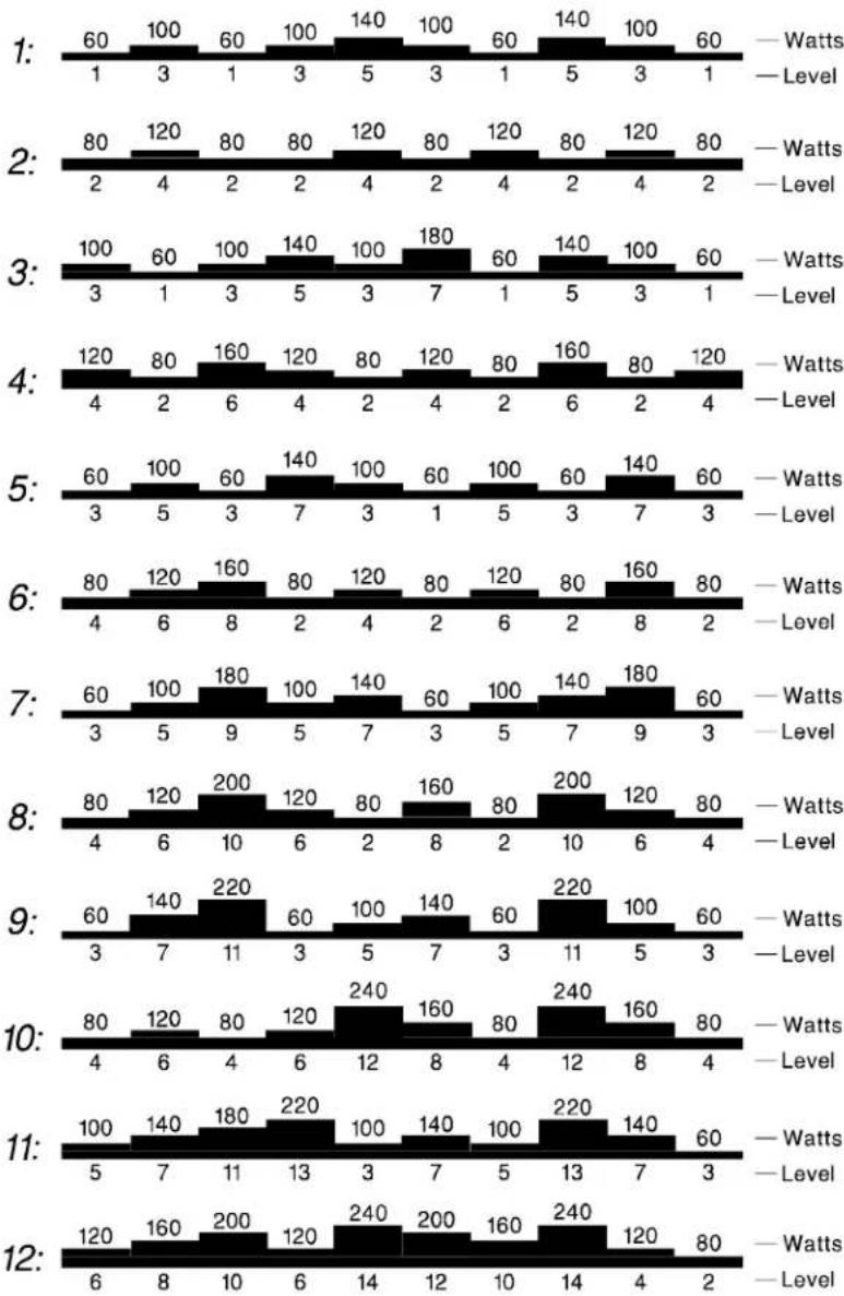
You can change the tension at any time during your workout.
If you stop in the middle of your workout, you will be prompted to "PEDAL TO START". All input information (DIST. or TIME, CAL., etc.) will be retained.
RESET:
After you have input your desired data for MAN'L, SET, INTV., PROGRAM and MODE, if you change your mind, press the RESET key, and this information will be cleared.
GENERAL:
If you pedal the cycle faster, the tension will lighter, conversely, pedaling slower will increase the tension.
MAINTAINING THE 5002 CYCLE
This cycle requires little maintenance. The cycle's low friction operation is dependent on keeping the unit as clean as possible.
Cleaning The Cycle
CAUTION: Turn off unit and disconnect the AC cord before cleaning.
Before your workout, use a dry cloth to clean the surface of the electronics package.
Note: NEVER POUR LIQUIDS ON THE ELECTRONICS PACKAGE. Should water, for some reason, get on the electronics package, immediately blow dry the electronics package.
To clean the plastic parts, use a mild detergent and make sure the unit is completely dry before operating. It is recommended that you keep all liquids away from the unit during operation. Spillage of liquids onto or into the machine will void the warranty.
TROUBLE SHOOTING:
There are two ways to turn on the cycle, either by pressing the "ON" key or simply by starting to pedal:
If You Press "ON" And There Is No Display:
A. Please pedal at a normal pace, approximately 50 RPM for more than 10 minutes, then stop pedaling and try pressing the "ON" key again.
B. If there is still no display after completing the above step, make sure all the connectors to the drive board are securely in place.
C. Remove and replace the RED WIRE of 3A fuse.
To Remove:
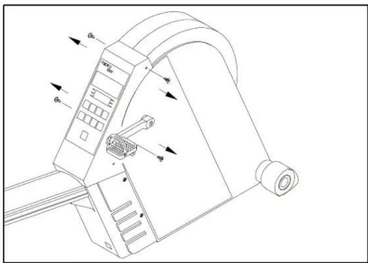
- Remove the electronics package (see Fig. 10).
text_image
Technical diagram of a mechanical device with labeled directional arrows and component labels(FIG.10)
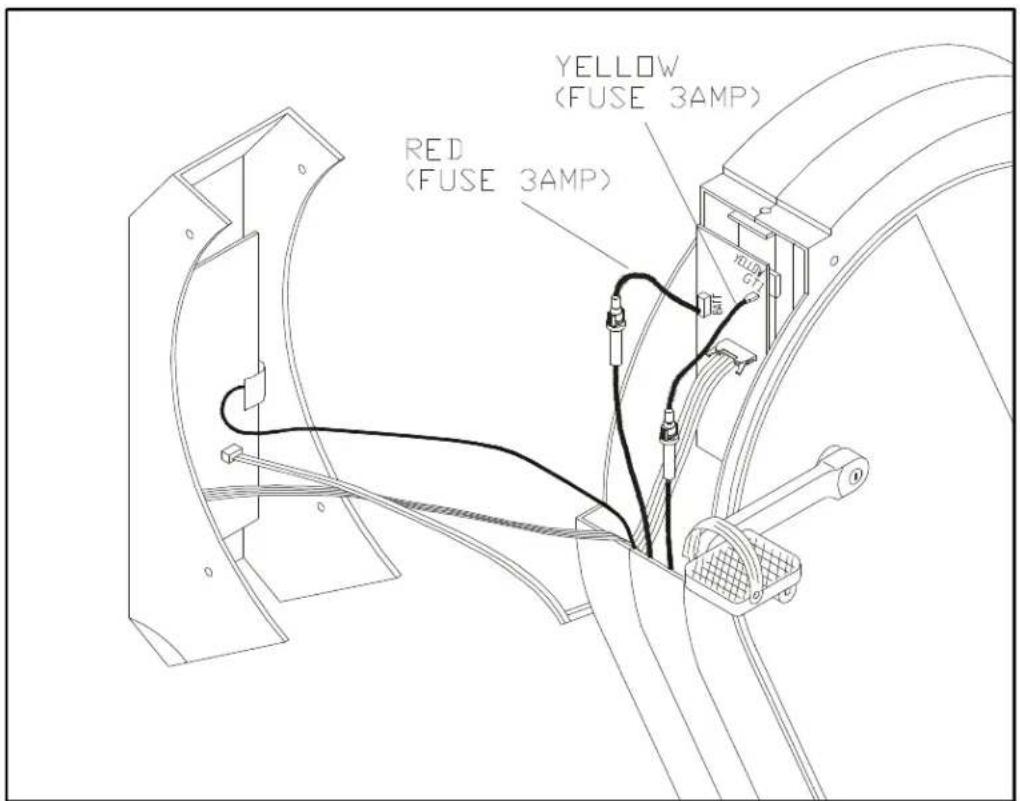
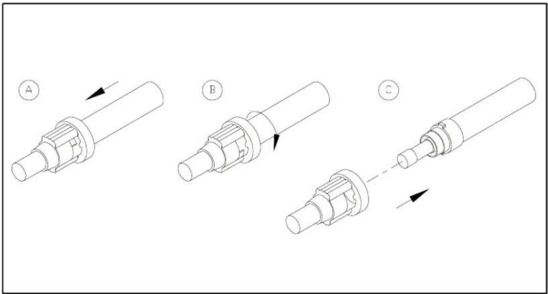
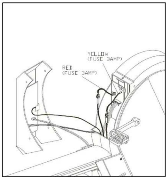
- There are two fuse holders near the drive board. Find the RED WIRE of 3A fuse holder (see Fig. 11). Push the fuse holder in and then turn the holder counterclockwise to remove the damaged fuse (see Fig. 12).
Note: Be careful not to let the fuse drop into the inside of the bike.
text_image
YELLOW (FUSE 3AMP) RED (FUSE 3AMP)(FIG.11)
text_image
Technical diagram showing three stages of a mechanical assembly with labeled arrows and component names A, B, C.(FIG.12)
To Replace:
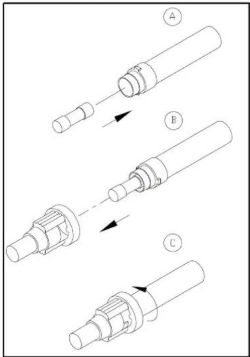
- Insert a new 3A fuse in the holder. Push the fuse and holder in, then turn clockwise to secure the fuse holder (see Fig. 14).
text_image
Technical diagram showing three-step assembly of a mechanical component with labeled parts A, B, and C.(FIG.13)
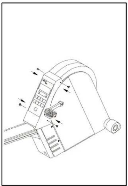
- Replace the electronics package to its place (see Fig. 15 & 16).
text_image
YELLOW (FUSE 3AMP) RED (FUSE 3AMP)(FIG.14)
text_image
Technical diagram of a mechanical device with labeled components and directional arrows indicating motion or force vectors.(FIG.15)
D. If there is still no display after the fuse has been replaced, the battery could be defective, or the expected life of the generator system battery has expired. Please check with your distributor for a battery recharge kit, or for the purchase of a replacement battery.
If You Have Pedaled At A Normal Pace For More Than 3 Seconds, And There Is No Display
a. Make sure all the connectors to the drive board are in place.
b. Remove and replace the YELLOW WIRE of 3A fuse. Please refer to the instructions as above (see Fig. 10-15).
c. If the unit still doesn't function properly, please contact your dealer.
If the HANDLEBAR REMOTE control unit doesn't function properly:
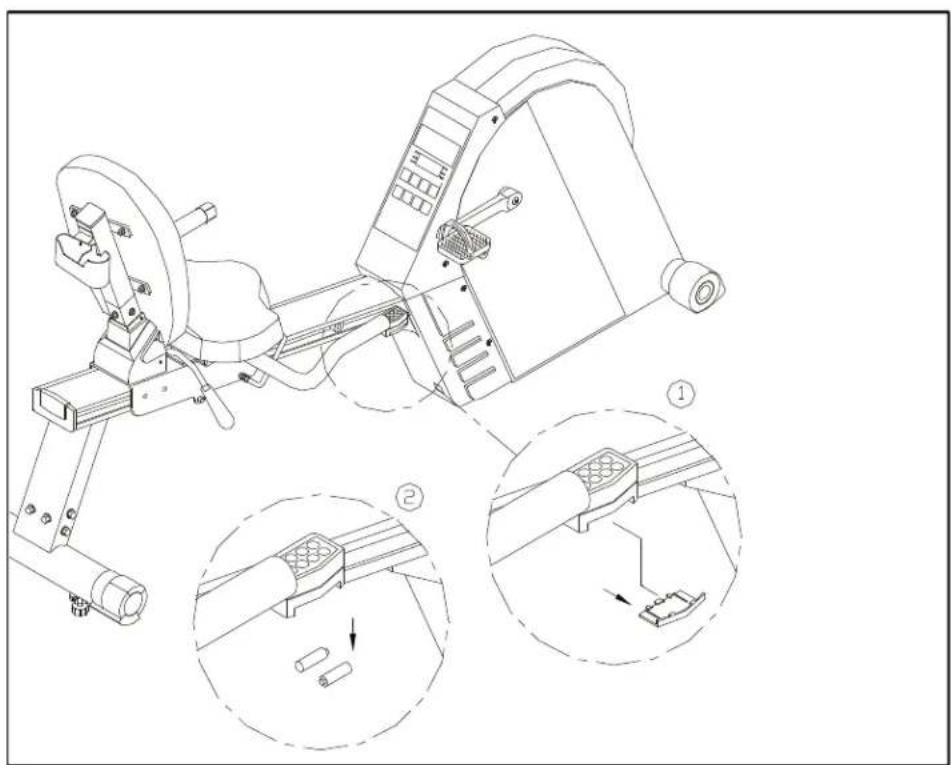
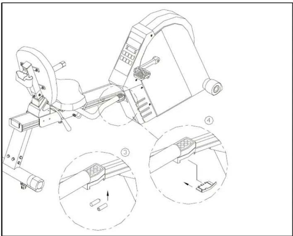
a. Replace the two AAA-batteries (see Fig. 16-17).
b. If the unit still doesn't function after replacing the batteries, please contact your nearest dealer.
natural_image
Technical line drawing of a mechanical exercise machine with three views (①, ②, ③) showing internal components and assembly steps (no text or symbols present)(FIG.16)
natural_image
Technical line drawing of a stationary exercise machine with three zoomed-in views (③, ④) showing internal components and motion indicators (no text or symbols present)(FIG.17)
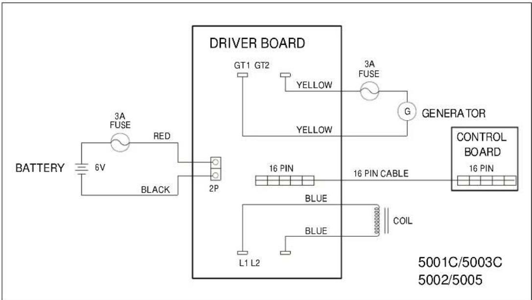
Wiring Schematic:
text_image
BATTERY 6V 3A FUSE RED BLACK 2P DRIVER BOARD GT1 GT2 YELLOW 3A FUSE YELLOW GENERATOR 16 PIN BLUE BLUE COIL L1 L2 16 PIN CABLE CONTROL BOARD 16 PIN 5001C/5003C 5002/5005Your Authorized Distributor
TABLE OF CONTENTS
A. SAFETY GUIDELINES .... 1
B. INTRODUCTION....2
C. ASSEMBLING YOUR CYCLE
List of parts.... 3
Step by step instructions....4
Floor level adjustment....8
Seat Adjustment....9
D. EXERCISING ON YOUR CYCLE
Using The Handle Bar Remote Control.... 9
Understanding The Electronics Package....10
Manual....10
Mode....10
Set....11
E. Using The Interval Mode
Interval 1....11
Interval 2....12
Program....13
Reset....15
F. GENERAL....15
G. MAINTAINING THE CYCLE
Cleaning The Cycle....15
H. TROUBLE SHOOTING.... 16