Sports 2000 (1970) - Automobil Datsun - Kostenlose Bedienungsanleitung
Finden Sie kostenlos die Bedienungsanleitung des Geräts Sports 2000 (1970) Datsun als PDF.


Benutzerfragen zu Sports 2000 (1970) Datsun
0 Frage zu diesem Gerät. Beantworten Sie die, die Sie kennen, oder stellen Sie Ihre eigene.
Eine neue Frage zu diesem Gerät stellen
Laden Sie die Anleitung für Ihr Automobil kostenlos im PDF-Format! Finden Sie Ihr Handbuch Sports 2000 (1970) - Datsun und nehmen Sie Ihr elektronisches Gerät wieder in die Hand. Auf dieser Seite sind alle Dokumente veröffentlicht, die für die Verwendung Ihres Geräts notwendig sind. Sports 2000 (1970) von der Marke Datsun.
BEDIENUNGSANLEITUNG Sports 2000 (1970) Datsun
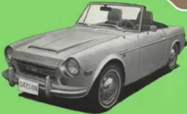
DATSUN SPORTS 1600·2000
OWNER'S MANUAL
MODEL SR(L)311
SP(L)311
natural_image
Illustration of a vintage convertible car with visible license plate and body (no text or symbols on the car itself)NISSAN MOTOR CO., LTD. Tokyo, Japan
FOREWORD
This Owner's Manual will not only acquaint you with the DATSUN'S features, but it will familiarize you with the operation of all instruments and controls, break-in procedure and the use of major optional equipment.
The instructions given in this manual should be fully observed so as to keep the performance and appearance of
your DATSUN like new. Please read through this manual and keep it in the glove compartment so that you can readily refer to it whenever necessary.
Remember that your DATSUN dealer is trained and equipped to maintain your new car so as to assure thousands of miles of trouble-free driving pleasure.
natural_image
Front view of a car with 'DATSUN' license plate, no visible text or symbols on the vehicle itselfCONTENTS
INSTRUMENTS AND CONTROLS 1
KEYS 6
SHIFTING 6
STARTING 6
NEW CAR BREAK-IN 7
SEATS WINDOW AND LOCKS 8
OPTION AND ACCESSORIES 11
VENTILATING AND HEATING 13
SOFT TOP (How to raise and lower) 15
ELECTRICAL SYSTEM 18
WHEELS AND TIRES 21
CHECKING AND ADJUSTMENT 23
CARBURETOR 25
DAILY CARE 29
PERIODIC MAINTENANCE 30
LUBRICATION CHART 30
CHECKING CHART 31
RECOMMENDED LUBRICANTS 33
GENERAL SPECIFICATIONS 34
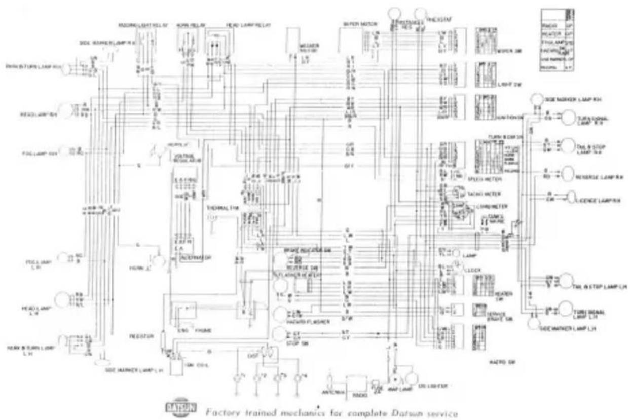
WIRING DIAGRAM 37
SPECIAL MAINTENANCE FOR EMISSION CONTROL SYSTEM 40
INSTRUMENT AND CONTROLS
text_image
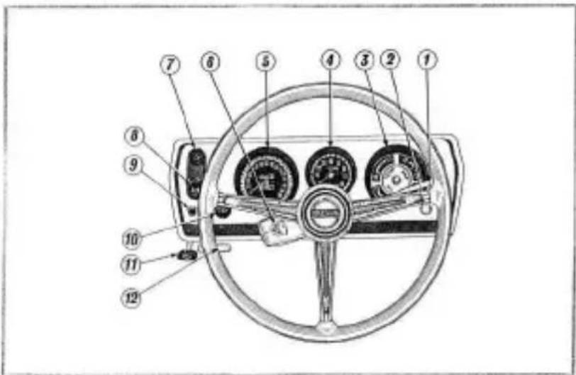
Diagram of a car steering wheel with numbered parts for identification① Turn indicator and head light earn selector lever
② Brake safety lamp
③ Combination meter
④ Tachometer
⑤ Speedometer
⑥ Ignition switch
⑦ Windshield wiper and washer switch
⑧ Throttle control knob
⑨ Rheostat knob
⑩ Light switch
⑪ Hood lock knob
⑫ Cowl ventilator lever
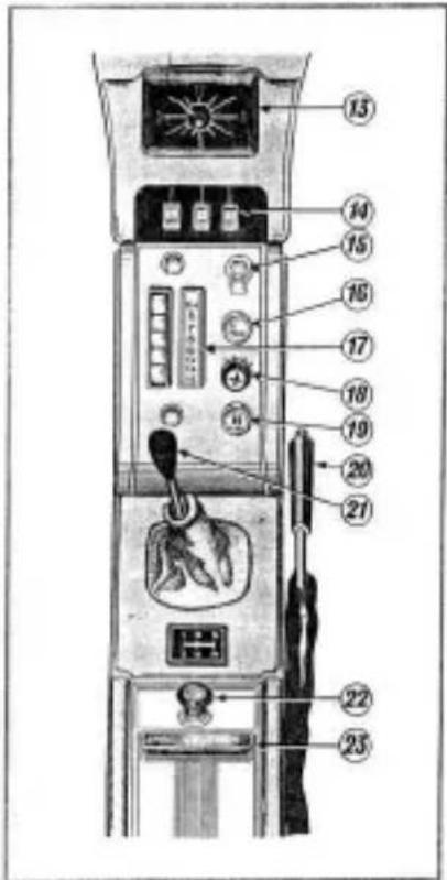
⑬ Clock
⑭ Heater control lever
⑮ Choke control knob
⑯ Brake safety lamp check knob
17 Radio
18 Fan switch
19 Hazard warning switch
20 Hand brake lever
21 Shift lever
②2 Cigarette lighter
② Ash tray
text_image
Labeled diagram of a device interior with numbered components and control panelINSTRUMENT AND CONTROLS
SPEEDOMETER
The speedometer indicates the car's forward speed. The odometer registers the total mileage and the trip indicator, adjustable by a trip canceler knob on the instrument panel, any desired distance.
HIGH BEAM INDICATOR LAMP
The high beam indicator light is situated on the speedometer face. It operates on high beam only.
TACHOMETER
The tachometer indicates the revolutions per minute. It is no good for the engine to drive constantly in the yellow shaded area.
Do not race up the revolutions up to the red shaded area.
TURN INDICATOR LAMP
The green light is situated on the tachometer face. It flashes simultaneously with the front and rear directional lights.
The fuel gauge, oil pressure gauge, water temperature gauge and ammeter are situated in the combination meter.
FUEL GAUGE
The fuel gauge is operated by an electrical indicator mechanism on the fuel tank when the ignition is switched on.
OIL PRESSURE GAUGE
The oil pressure gauge indicates the operating pressure of the lubricant in the engine. When the pressure while driving does not go up, it is necessary to stop the engine immediately and check the oil level. If the oil level is normal, an authorized dealer should be consulted.
WATER TEMPERATURE GAUGE
The temperature of the coolant is electrically indicated by the gauge when the ignition is switched on. When the ignition is switched off, the needle moves to the cold position.
AMMETER
The ammeter indicates the amount of the electric current charged by the alternator to the battery.
INSTRUMENT AND CONTROLS
CHOKE CONTROL KNOB
By turning the knob counter-clockwise, the choke control can be pulled out to its desired position and with a slight right twist locked in place.
THROTTLE CONTROL KNOB
By operating the throttle control knob in the manner described above, the engine revolution is maintained at the same r.p.m. without pressing down the accelerator pedal.
WINDSHIELD WIPER AND WASHER SWITCH
The wiper blades are operated by pulling the knob, in the 1st stage the blade moves at low speed and in the 2nd stage the blade moves at high speed. In any stages including original stage, the two jets spray the fluid to the windshield by turning the same knob clockwise.
LIGHT SWITCH
This is a pull-type switch with two positions. The first stage controls the instrument lights as well as the
tail, parking and number plate lights. The second stage controls the head lights.
By turning the switch clockwise, the fog lights go on.
PASSING LIGHT SWITCH (Optional for L.H. drive)
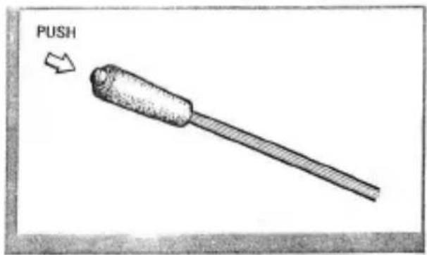
By pushing and releasing the button located at the top of the turn indicator lever, the high beams of the head lights will be turned on and off.
text_image
PUSHINSTRUMENT AND CONTROLS
IGNITION SWITCH
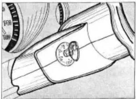
The ignition switch is combined with the steering lock device and the switch positions are illustrated in the figure provided.
This five position switch controls the engine ignition system and most of the electrical equipment in your car. All accessories can be operated when the key is in the "ACC" position without the engine running.
STEERING WHEEL LOCK
The steering can be locked only when the key is pulled out in the "LOCK" position.
KEY WARNING BUZZER
(For USA and Canada)
Failure to remove the key from the ignition switch when in the "LOCK" position will cause a warning buzzer to sound when the left door is opened.
RHEOSTAT KNOB
The brightness of the instrument panel lights can be adjusted by turning the knob.
BRAKE SAFETY LAMP
The brake safety lamp on the instrument panel indicates if a difference in pressure exists between the front and rear brake system. If this light goes on, it is necessary to check the brake system.
BRAKE SAFETY LAMP CHECK KNOB
By pulling the brake safety lamp check knob, the brake safety lamp can be checked for proper operation. If the lamp goes on, the brake safety lamp operates normally.
natural_image
Technical line drawing of a mechanical component with a circular inset showing a central feature (no text or symbols)INSTRUMENT AND CONTROLS
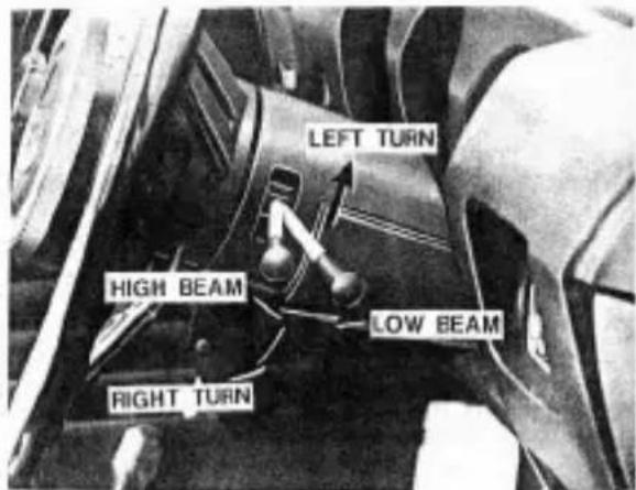
TURN INDICATOR AND HEAD LIGHT BEAM SELECTOR LEVER
Move the lever downward for a right turn and upward for a left turn. Move the lever toward the steering wheel to dim the headlights.
HAZARD WARNING SWITCH (For USA and Canada)
By pulling the knob on the separate housing beneath the instrument panel center, all directional lamps flicker at the same time to inform cars in the event of some trouble happening in your car. In this case the two green lights on the instrument panel flicker simultaneously with all directional lamps.
text_image
LEFT TURN HIGH BEAM LOW BEAM RIGHT TURN
natural_image
Front view of a black sports car with visible headlights and grille (no text or symbols)KEYS
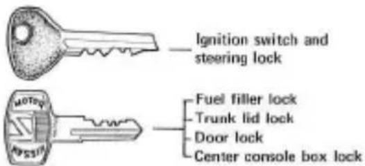
Two different keys operate the various locks on your Datsun.
Record these key numbers. They enable your DATSUN dealer to replace lost key.
text_image
Ignition switch and steering lock Fuel filler lock Trunk lid lock Door lock Center console box lockSHIFTING
The shifting diagram which is illustrated on the center console is as follows; synchromesh is provided on all forward gears. As the transmission utilizes the servo type synchromesh, there is the possibility of the driver not depressing the clutch pedal sufficiently and as a result causing synchronizer damage. The clutch pedal should therefore be fully depressed when shifting gears.
natural_image
Simple line drawing of a mechanical component with a handle and base (no text or symbols)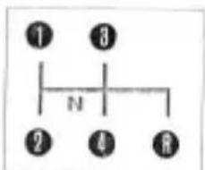
text_image
① ③ N ② ④ ⑧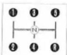
text_image
① ③ ⑤ N ② ④ RSP(L)311
SRIL311
Place the gear shift lever in the neutral position and turn the ignition switch on. The electrical starter is operated by turning the key further to the "START" position. As soon as the engine starts, release the key which returns automatically to the switched-on ignition position.
COLD ENGINE
Pull out the choke control knob and start engine without depressing accelerator pedal. Push in the choke knob after the engine has warmed up enough to run on a normal fuel mixture.
NEW CAR BREAK-IN
Life and economy of the car depend largely on the maintenance and care given to it during first 2,000 km (1,500 miles). Not only the engine but also the car benefits from proper break-in.
The car should be driven neither too gently nor under full power, i.e.:
* 4,000 r.p.m. should not be exceeded in any gear during break-in.
* It is recommended to drive mostly between 3,000 \~ 3,500 r.p.m. Change speed of tea! Drive only for very short periods at full throttle!
* Do not drive at full throttle in lower gears!
* Other than in the case of emergency, avoid heavy braking or rough usage of the brakes, before the friction pads are fully bedded in.
Maximum speed limit for the first 2,000 km (1,500 miles)
| Transmission | 1st | 2nd | 3rd | 4th | 5th | |
| SP(L)311 | 4 speed | 33 km/h(20 miles/h) | 45 km/h(28 miles/h) | 65 km/h(40 miles/h) | 87 km/h(55 miles/h) | |
| SR(L)311 | 5 speed | 35 km/h(22 miles/h) | 60 km/h(38 miles/h) | 83 km/h(52 miles/h) | 110 km/h(69 miles/h) | 130 km/h(80 miles/h) |
SEATS,WINDOW AND LOCKS
SEAT ADJUSTMENT
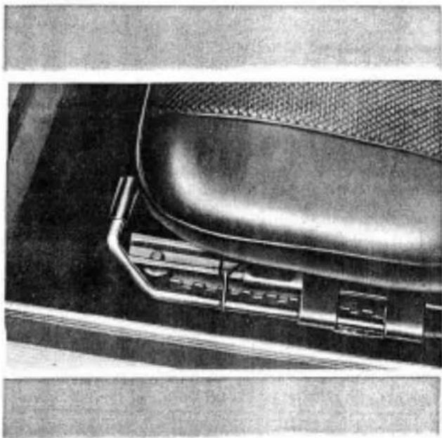
The seat can be adjusted to the desirable position by operating the lever located under the seat. On the seat back upper, the headrests are attached as an optional part. (Standard for USA and Canada)
SEAT INCLINATION
By inclining the seat ±5^ with adjusting the stopper bolt under the seat, best desirable driving position can be obtained.
natural_image
Close-up of a car seatbelt with metal bracket and mesh grille (no visible text or symbols)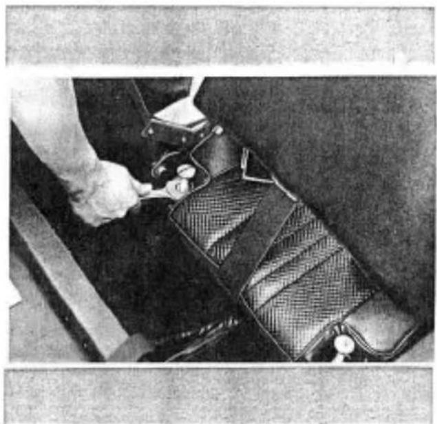
natural_image
Close-up of a hand adjusting a car seatbelt with a mesh cover (no visible text or symbols)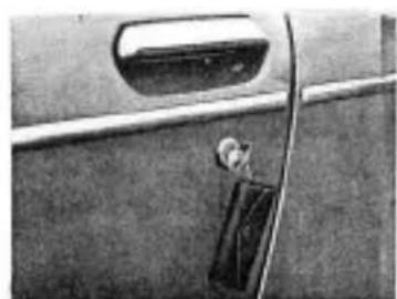
natural_image
Close-up of a car door handle and side panel showing a black clip (no text or symbols visible)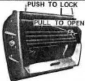
text_image
PUSH TO LOCK PULL TO OPEN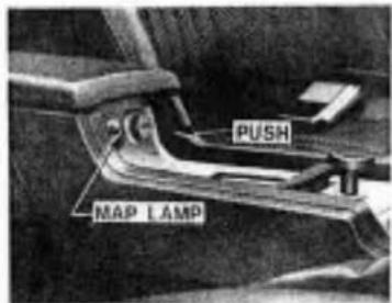
text_image
PUSH MAP LAMPSEATS,WINDOW AND LOCKS
DOOR LOCKS
To lock the front door, insert the key and turn it clockwise. Turn the key counter-clockwise to unlock the door.
Any door from interior can be locked by just pushing down the lock knob and unlocked by pulling up it.
GLOVE COMPARTMENT LOCK
By pushing the lock button, the lid of the glove compartment can be opened.
CENTER CONSOLE BOX LOCK
To open the center console box lid locked, insert the key, turn it clockwise and push the button. The center console box lid which is not locked will be opened by just pushing its button.
By pushing the lens of the map lamp, the map lamp goes on.
SEATS WINDOW AND LOCKS
TRUNK LID LOCK
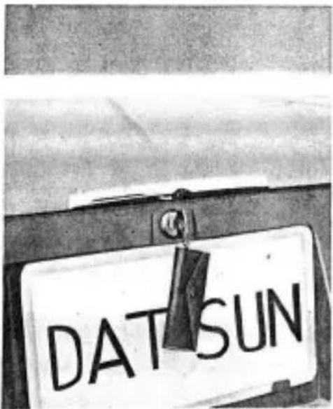
To open the trunk lid, insert the key and turn it clockwise and the trunk lid will open by spring action. To close it, just press on the lid and remove the key then it will be locked completely.
text_image
DAT SUNHOOD LOCK
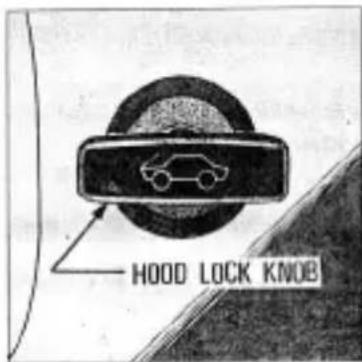
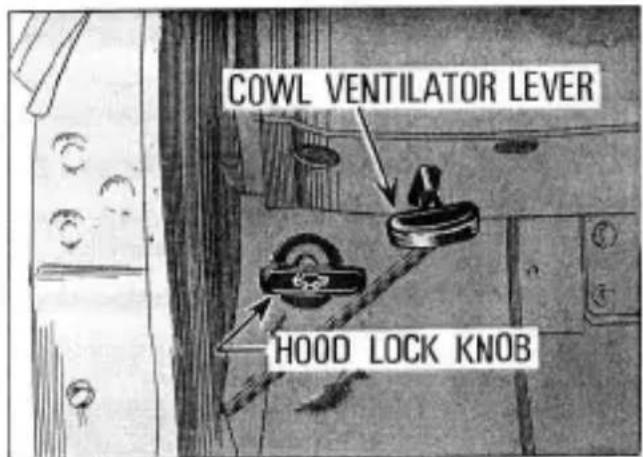
Pull the hood lock knob located at the lower area of the instrument panel, then the hood will open slightly and raise up the hood by releasing the safety catch on the hood assembly.
text_image
HOOD LOCK KNOB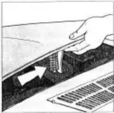
natural_image
Hand holding a tool interacting with a textured surface, with an arrow indicating direction (no text or symbols visible)
natural_image
Blank or nearly blank image with no discernible text, symbols, or structured content.FUEL FILLER CAP LOCK
To open, insert the key and turn it counter-clockwise. To close, turn it clockwise.
OPTION AND ACCESSORIES
RADIO (Optional)
natural_image
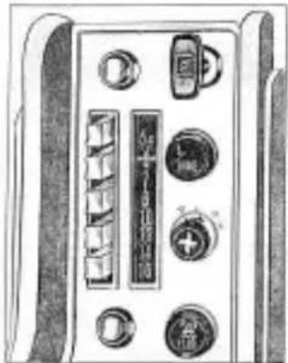
Front panel of a vintage electronic device showing buttons, dials, and a central screen (no visible text or symbols)The radio has five push buttons for station selection. Other stations may be selected by the manual tuning knob.
Adjust the Push Button as follows:
-
Pull the selector button straight out until it stops, tune in the station you want with the manual tuning knob.
-
After the station is clearly tuned in, push the selector button straight in until it stops, and release it.
RADIO ANTENNA
The antenna pops out by inserting and lightly pushing the antenna key. Then extend the antenna.
CLOCK
By pushing and turning the knob clockwise, the time can be corrected.
ASH TRAY
Ash tray installed on the center console can be removed for cleaning.
CIGARETTE LIGHTER
To operate the cigarette lighter push in the knob. It will stay in this position until the lighter element is at the correct temperature, then it will pop back into its former position.
It should then be pulled completely out of its holder for use.
OPTION AND ACCESSORIES
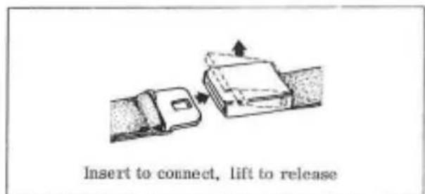
SAFETY SEATS BELTS
text_image
Insert to connect, lift to release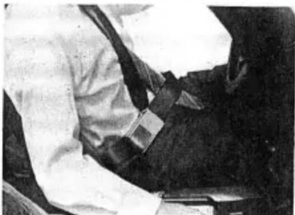
natural_image
Close-up of a person wearing a white coat and dark suit, seated at a table (no visible text or symbols)Before fastening a seat belt, always adjust the seat to the proper position.
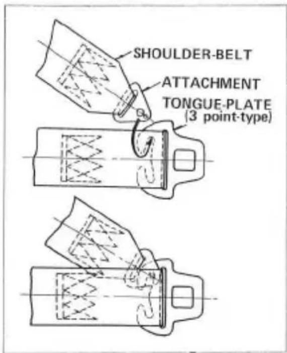
text_image
SHOULDER-BELT ATTACHMENT TONGUE-PLATE (3 point-type)VENTILATING AND HEATING
COWL VENTILATOR
The air flows into the interior of cab from the intake in front of the windshield by operating cowl ventilator lever located at the lower area of the instrument panel.
HEATER (Optional)
The operation of the heater-ventilator system is controlled by three levers on the instrument panel (Temperature control lever, OUT-IN air control lever, Room & Defroster control lever) and the fan switch located on the separate housing.
text_image
COWL VENTILATOR LEVER HOOD LOCK KNOB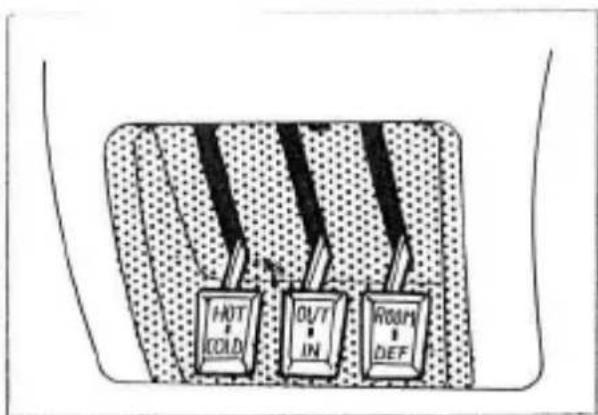
text_image
HOT COLD OUT IN ROOM DEF
VENTILATING AND HEATING
text_image
Diagram showing four sequential steps of a device or device with labeled components and connectors, likely illustrating a process or assembly.TO VENTILATE THE CAR
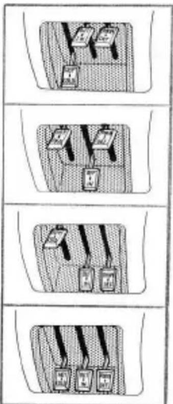
By moving the temperature lever downward, the OUT-IN air control lever and room and defroster control lever upward then turning the fan switch clockwise, you can get fresh air directly into the interior.
TO HEAT THE CAR
- Move the temperature control lever to the "HOT" position. In case that you get hotter air, move the OUT-IN air control lever to "IN" position.
- When the temperature gauge indicates that the engine is warm, turn the fan switch clockwise.
- Move the room and defroster control lever to "ROOM" position.
TO DEFROST THE WINDSHIELD
Operate the heater in the manner described above. However, turn the room and defroster control lever to the "DEF" position.
In case of defrosting the windshield more powerfully, move the OUT-IN air control lever to "IN" position.
TO DEFOG THE WINDSHIELD
Use the same procedure as for defrosting action except set the temperature control lever to the "COLD" position.
SOFT TOP (How to raise and lower)
TO LOWER THE SOFT TOP
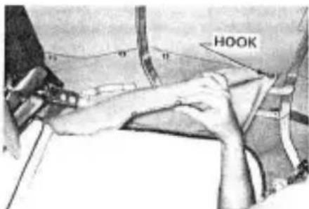
text_image
HOOK1 Unfasten the upper hook of the soft top frame cover.
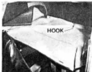
text_image
HOOK3 Fasten the compartment cover with hooks.
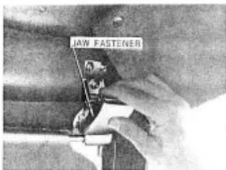
text_image
JAW FASTENER2 Unfasten the jaw fastener by pulling it.
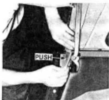
text_image
PUSH4 Detach the pushing plate from the bracket.
SOFT TOP (How to raise and lower)
natural_image
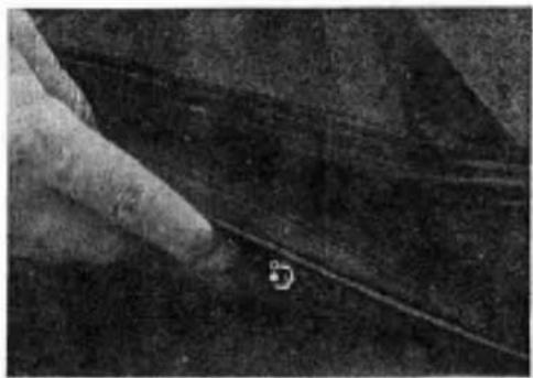
Close-up of a hand holding a thin, dark fabric or material with a small circular mark near the tip (no visible text or symbols)5 Unfasten the snaps from the front to rear by turning them.
natural_image
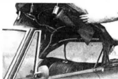
Close-up of a damaged vehicle interior with visible structural damage and wiring (no text or symbols)6 Raise the soft top backwards.
text_image
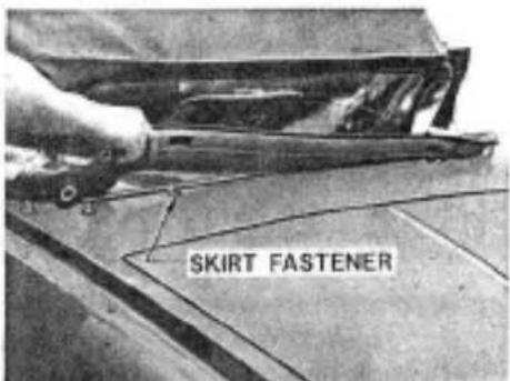
SKIRT FASTENER7 Take out the skirt frame from the skirt fastener.
natural_image
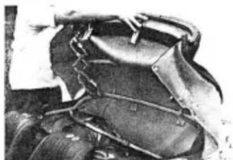
Close-up of a mechanical component with no visible text or symbols8 Fold the canvas in position without creasing the side and rear window.
SOFT TOP (How to raise and lower)
natural_image
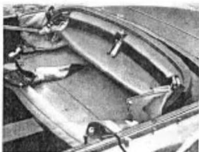
Close-up of a mechanical component with curved surfaces and mounting brackets (no visible text or symbols)9 Lower the soft top into storage area.
natural_image
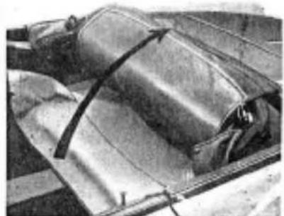
Close-up of a metallic cylindrical object with a curved arrow indicating direction (no visible text or symbols)10 Cover the folded canvas with the compartment cover.
natural_image
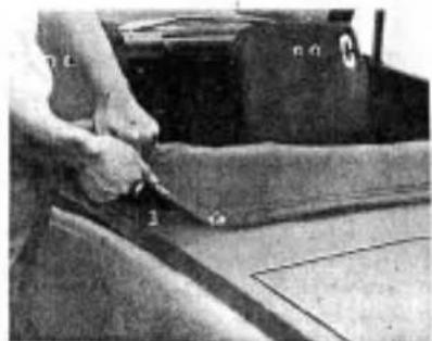
Close-up of a hand using a tool to cut or repair a piece of material on a surface (no visible text or symbols)11 Fasten the compartment cover with snaps.
text_image
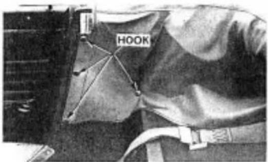
HOOK12 Fasten the compartment cover with inner hooks at both right and left sides.
text_image
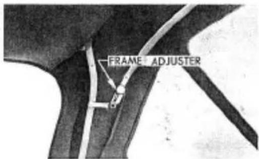
FRAME ADJUSTER13 Adjust the canvas tension with the frame adjuster.
ELECTRICAL SYSTEM
natural_image
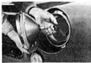
Close-up of hands operating a car wheelbelt with a handle (no visible text or symbols)HEAD LAMPS
To change the sealed beam units, remove the rim cover and three screws which secure the lamp assembly as shown in the following illustrations. Whenever a sealed beam is replaced, the head light should always be checked for alignment and adjusted if necessary.
Sealed beam units : (12V - 50/40W)
natural_image
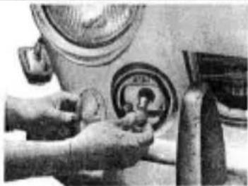
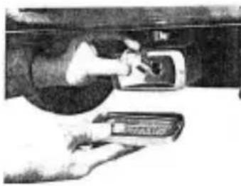
Close-up of hands operating a mechanical switch with a circular dial (no visible text or symbols)DIRECTIONAL AND PARKING LAMPS (Front)
Remove the two screws and replace the bulb.
Bulbs: (12V - 25/8W)
natural_image
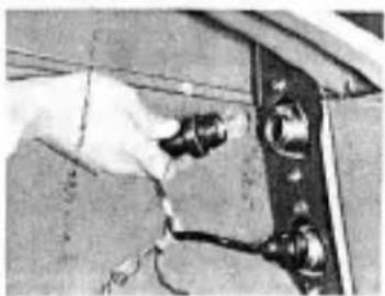
Close-up of a hand adjusting a metal bracket with wires (no visible text or symbols)DIRECTIONAL, TAIL AND STOP LAMPS (Rear)
Remove the socket, located inside the trunk room, by turning it counter-clockwise and then replace the bulbs.
Bulbs :
Stop and tail lights (12V-25/8W)
Directional lights (Amber lens) (12V-25W)
Directional stop and tail lights (for USA and Canada) (12V-25/8W)
(Red lens)
ELECTRICAL SYSTEM
natural_image
Person using a computer in a car (no visible text or symbols)BACK UP LAMP
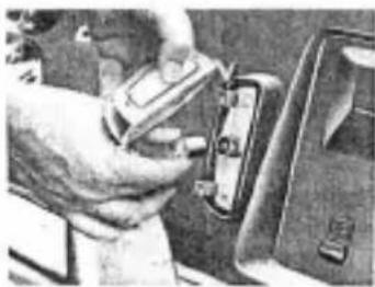
Remove the two screws securing the back up lamp lens. Press down the bulb, turn it counter-clockwise and remove.
Bulb: (12V - 15W)

natural_image
Illustration of a hand pressing down on a car seatbelt (no text or symbols visible)LICENSE PLATE LAMP
Use the same procedure as for the back up lamp.
natural_image
Close-up of a hand using a tool to adjust or install a mechanical component (no visible text or symbols)Bulb: (12V - 8 W)
(For USA and Canada)
SIDE MARKER LAMP
(For USA and Canada)
Front
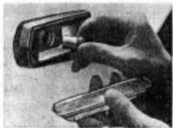
Remove the screw securing the side marker lamp lens. Press down the bulb, turn it counterclockwise and remove.
Rear
Turn the side marker lamp lens and remove it. Press down the bulb, turn it counter-clockwise and remove.
Blub: (12V - 8W)
FUSES
Fuses are located in the glove compartment. If a fuse needs to be replaced, refer to the specifications listed on the back of the fuse box cover.
natural_image
Close-up of a hand holding a small electronic device with a lens (no visible text or symbols)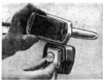
natural_image
Close-up of a hand holding a flip phone with a circular button (no visible text or symbols)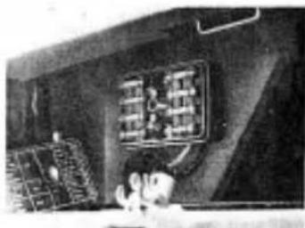
natural_image
Interior view of a ship's bowing with crew members on deck (no visible text or symbols)ELECTRICAL SYSTEM
BATTERY
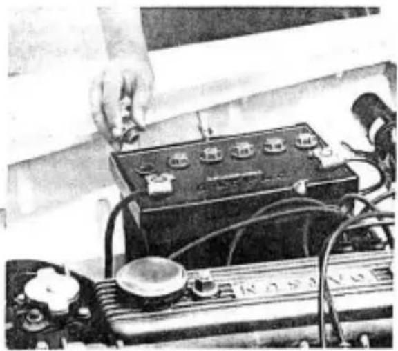
Check the electrolyte level in the battery about once a month. If necessary added distilled water to bring the level up approximately 5 mm above the plates. Do not overfill.
To prevent corrosion and leakage of current keep the top of battery clean and dry. Also keep the terminals clean and well covered with petroleum jelly.
natural_image
Close-up of a hand adjusting a car battery with visible circuit lines and components (no text or symbols)CHECKING SPECIFIC GRAVITY
Check the specific gravity of the electrolyte in each of the cells by hydrometer.
Specific gravity should be as follows.
| Full charged specific gravity at 68°F, 20°C | |
| Frigid climates | 1.28 |
| Tropical climates | 1.26 |
| Other climates | 1.23 |
natural_image
Uniform gray textured surface with no visible text, symbols, or distinct featuresWHEELS AND TIRES
Performance, ride and handling qualities of any car are greatly influenced by tire condition and pressure. Tire pressure lower than recommended will reduce
tire life and ride qualities. Pressure above those recommended affects the life and ride of the vehicle adversely, because "hard" tires tend to magnify, rather than absorb road shocks.
Recommended tire pressure
| SpeedsTire | 150 km/h(94 mile/h) | 175 km/h(109 mile/h) | 200 km/h(125 mile/h) | |
| 5.60S14-4 | 1.5 kg/cm ^2 (22 lb/in ^2 ) | 1.8 kg/cm ^2 (25.5 lb/in ^2 ) | ||
| 6.45H14-4(Optional) | 1.5 kg/cm ^2 (22 lb/in ^2 ) | 1.8 kg/cm ^2 (25.5 lb/in ^2 ) | 2.0 kg/cm ^2 (28.4 lb/in ^2 ) | 2.3 kg/cm ^2 (32.7 lb/in ^2 ) |
Note: The tire pressure should be measured under cold condition.
TIRE ROTATION
To equalize tire wear, tires should be rotated every 10,000 km (6,000 miles) as shown in the diagram.

natural_image
Line drawings of four different types of screwdrivers (no text or symbols)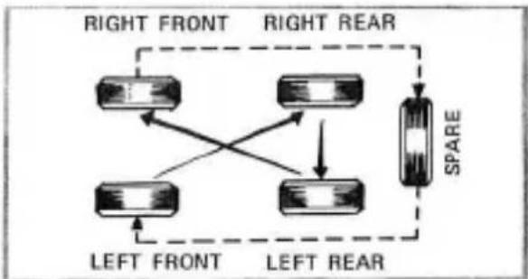
flowchart
graph TD
    A["Left Front"] --> B["Central Device"]
    C["Left Rear"] --> D["Central Device"]
    E["Right Front"] --> F["Central Device"]
    G["Right Rear"] --> H["Central Device"]
    I["SPARE"] --> J["Central Device"]
    style A fill:#f9f,stroke:#333
    style C fill:#f9f,stroke:#333
    style E fill:#f9f,stroke:#333
    style G fill:#f9f,stroke:#333
    style I fill:#f9f,stroke:#333
    style B fill:#ccf,stroke:#333
    style D fill:#ccf,stroke:#333
    style F fill:#ccf,stroke:#333
    style H fill:#ccf,stroke:#333
    style J fill:#ccf,stroke:#333
WHEELS AND TIRES
JACKING UP
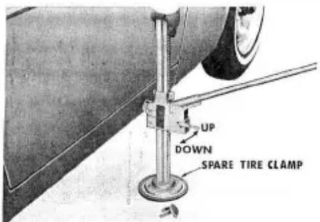
At first, put the wheel stopper on the opposite side wheel to be removed, then put the jack nose into the jacking hole of the body sill, in this case use the spare tire clamp plate for the jack stand.
Pull upward the small lever near the jack handle socket. When the jack is properly aligned, alternately raise and lower the handle and the car will rise.
To lower the car, place the small lever in the down position and use the same motion employed to raise the car.
text_image
UP DOWN SPARE TIRE CLAMPSPARE TIRES AND JACK
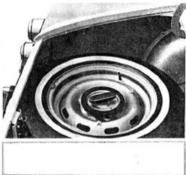
The spare wheel and jack are stored in the rear luggage compartment fixed with a spare wheel clamp.
natural_image
Close-up of a car wheel rim with concentric rings and mounting brackets (no visible text or symbols)CHECKING AND ADJUSTMENT
BRAKE AND CLUTCH LEVEL
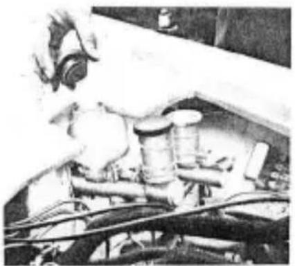
The brake and clutch fluid should be kept at the normal level marked on the master cylinder reservoir tank. If the brake safety light on the instrument panel goes on, it is necessary to check the brake system.
natural_image
Close-up of a mechanical assembly with visible gears and tubing (no text or symbols)ENGINE OIL LEVEL
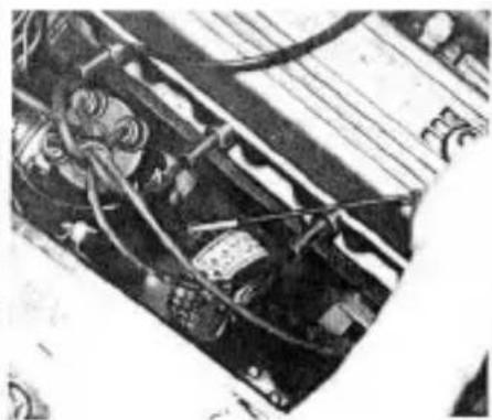
The engine oil level should be checked prior to starting the engine with the car standing on the level ground.
natural_image
Close-up of an electronic circuit board with visible wiring and components (no readable text or symbols)COOLING WATER
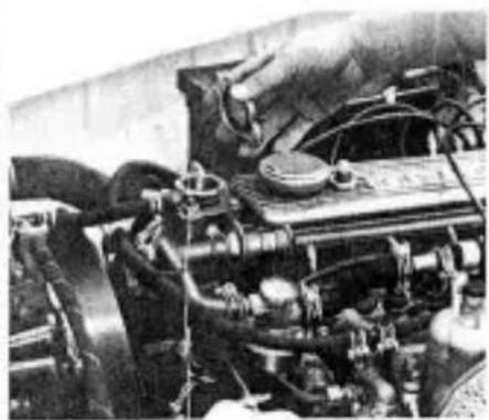
As NISSAN LONG LIPE COOLANT (L. L. C.) is added to the cooling water, which is available for any season, the changing interval of the coolant is 2 years or 36,000 km (24,000 miles) and checking interval is 3,000 km (2,000 miles).
natural_image
Close-up of an engine bay with visible hoses and components (no text or symbols)CHECKING AND ADJUSTMENT
natural_image
Three-panel black-and-white photo showing mechanical components and wiring (no visible text or symbols)OIL FILTER
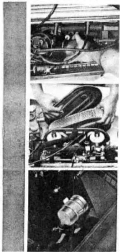
After the first 1,000 km (600 miles) driving, drain and refill with an oil of the proper viscosity for the prevailing temperature.
Refer to the chart of recommended oil. After the first 3,000 km (2,000 miles), the oil filter cartridge should be replaced by a new one. After that, the cartridge should be renewed every 10,000 km (6,000 miles).
AIR CLEANER
The air cleaner element for DATSUN SPORTS 1600 is of the paper filter type. It must be cleaned every 3,000 km (2,000 miles) and replaced every 18,000 km (11,000 miles).
The element for DATSUN SPORTS 2000 is of the viscous type. Since it has been specially treated there is no need to clean it but it should be replaced every 20,000 km (12,000 miles) under normal conditions. In dusty areas, the element should be replaced more often.
FUEL STRAINER
The fuel strainer is of the cartridge type and should be replaced at intervals not to exceed 40,000 km (24,000 miles).
FAN BELT
When it is necessary to check the fan belt tension, loosen the generator adjusting link bolt and adjust the tension by moving the generator.
CARBURETOR
THROTTLE VALVE CLOSE ADJUSTMENT
Throttle valve close adjustment must be carefully done since the fuel consumption will increase and engine output will be lost if each throttle valve of both carburetors arranged in parallel are not closed simultaneously.
SU Type
R-engine for SP(L)311
-
Inspect damper oil in the carburetors. Top up if necessary.
-
Remove the air cleaner.
-
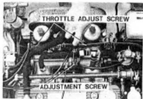
Loosen the throttle adjust screws on front and rear side carburetor so that the tip of them does not touch the stoppers.
-
Set the rear side connecting rod length to the standard measurement 7 cm (2.76 in.).
-
Start the engine and warm up thoroughly.
-
Set the engine speed at 800 \~ 1,000 r.p.m. by screwing in the adjustment screw on the auxiliary shaft.
-
Adjust the length of front side connecting rod so that the air inlet volume on front and rear side will be uniform.
-
Lower the engine speed to 700 r. p. m. by turning back the adjustment screw on the auxiliary shaft carefully.
-
Then screw in the throttle adjust screws on front and rear side carburetor so that the tip of them will touch the stoppers.
-
Ensure the air inlet volume are even for both front and rear carburetor by adjusting the throttle adjust screw.
text_image
THROTTLE ADJUST SCREW ADJUSTMENT SCREWU2D-engine for SR(L)311
-
Inspect damper oil in carburetors. Top up if necessary.
-
Remove the air cleaner.
CARBURETOR
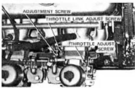
- Loosen the throttle adjust screws on front and rear side carburetor so that the tip of them does not touch the stoppers.
- Start the engine and warm up thoroughly.
- Set the engine speed at 800 \~ 1,000 r. p. m. by screwing in the adjustment screw on the auxiliary shaft.
- Adjust the throttle link adjust screw so that the air inlet volume on front and rear side will be uniform.
text_image
ADJUSTMENT SCREW THROTTLE LINK ADJUST SCREW THROTTLE ADJUST SCREW-
Lower the engine speed to 700 r. p. m. by turning back the adjustment screw on the auxiliary shaft carefully.
-
Then screw in the throttle adjust screws on front and rear side carburetor so that the tip of them will touch the stoppers.
- Ensure the air inlet volume is even for front and rear carburetor by adjusting the throttle adjust screw.
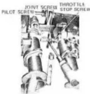
SOLEX Type
text_image
JOINT SCREW PILOT SCREW THROTTLE STOP SCREW- Start the engine and warm up thoroughly.
- Set the engine speed at 800 - 1,000 r. p. m. by screwing in the throttle stop screw.
- Adjust the joint screw so that the air inlet volume on front and rear side will be uniform.
CARBURETOR
- Lower the engine speed to 700 r. p. m. by turning back the throttle stop screw.
- Ensure the air inlet volume is even for both front and rear carburetor by adjusting the throttle stop screw.
IDLE ADJUSTMENT
As for the engine fitted with an emission control system, do not touch the idle adjust nuts except for carburetor overhaul, because they have precisely calibrated at the factory.
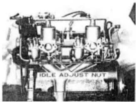
SU Type
natural_image
Close-up of an engine assembly with visible gears and shafts (no text or symbols)Idle adjustment is done by throttle adjust screw and idle adjust nut after the engine is warmed up. When idle adjust nut is turned to the right and screwed in, the fuel flow is decreased and when it is turned to the left and loosened, it is increased.
- Loosen idle adjust nuts on front and rear side carburetor about two turns from the complete fastening.
Then screw in the throttle adjust screw on front side carburetor 2-3 turns and loosen throttle adjust screw so that the top of it will not touch the stopper. Then start the engine.
-
Lower engine revolution down to about 700 r.p.m. by turning back the front side throttle adjust screw carefully.
-
Screw in idle adjust nuts on both front and rear side each by 1/8 turn in turn to find the point where engine revolution is the fastest and steadiest, and fix the nuts there. If you can not find this point where engine revolution is the fastest and steadiest by screwing in, return the idle
CARBURETOR
adjust nuts to the original place and begin loosening them on front and rear side in turn by 1/8 turn until you find finally such a point and fix. (The adjustment of idle adjust nuts ranges within +1/2 turnings.)
- After this, loosen throttle adjust screw on front side to lower engine revolution.
Repeating 3. 4. processes once or twice, adjust the engine revolution until it gains steady 600 - 700 r.p.m.
- Finally, tighten the throttle adjust screw until the top of it touches the stopper (just before engine revolution begins to increase).
After this adjustment is over, remove the air cleaner to see if the suction piston's lifts on front and rear side carburetors are equally adjusted, and if not, readjust them by the throttle adjust screw.
a. Move the auxiliary shaft of manifold to race engine a few times.
b. Ensure the suction piston lifts on front and rear side of carburetors are same.
c. If not same, fasten carburetor throttle adjust
screw slightly on the less lifted side and loosen it slightly on more lifted side.
Keeping engine revolution as it was at the first time, repeat a. b. c. process once or twice to make the front and rear side lifts equal.
SOLEX Type
-
After ensuring all throttle valves are uniform, return each pilot screws for about one round from the complete close. Then, screw the throttle stop screw in a little degree and let the engine start.
-
Set the engine speed to about the required idling speed by the throttle stop screw.
-
Set it to the highest engine speed by adjusting each pilot screw for about 1/4 round separately.
-
After obtaining a little higher engine speed, set it to the required idling speed again by adjusting the throttle stop screw.
-
Repeat this operation 2\~3 times, and the required idling can be obtained.
natural_image
Front view of a silver sports car with headlights and grille (no visible text or symbols)
natural_image
Front view of a car with a license plate and 'DATSON' license plate (no visible text or symbols beyond the license design)DAILY CARE
Before driving or whenever you call at a gas-station, be sure to check the following items.
- Check the radiator coolant.
- Check the engine oil.
- Check the battery.
Unscrew each filler cap and check the fluid level. If necessary, add distilled water to bring the level up to approximately 5 mm (0.2 inch) above the plate.
- Check tire pressure, wear and scars.
Refer to "WHEELS AND TIRES" of page 21.
- Check directional indicators, horn and all lights and switches for proper operation.
- Check the windshield washer fluid level.
- Check leakage and amount of fluid in brake and clutch master cylinders.
- Check clutch and brake operation.
- Check steering wheel play.
PERIODIC MAINTENANCE
To assure satisfactory performance of your car, be sure to have the periodic checks carried out at an authorized dealer.
LUBRICATION CHART
| Interval | LUBRICATION | Period | ||||||||||||||||
| 20000 km(10000 miles) | 40000 km(30000 miles) | 25000 km(12000 miles) | 10000 km(9000 miles) | 5000 km(3000 miles) | 10000 km(6000 miles) | 9000 km(2000 miles) | 8000 km(4000 miles) | 70000 km(6000 miles) | 60000 km(3000 miles) | 50000 km(12000 miles) | 40000 km(10000 miles) | 30000 km(18000 miles) | 20000 km(21000 miles) | 10000 km(3000 miles) | 80000 km(3000 miles) | 60000 km(27000 miles) | 50000 km(3000 miles) | |
| ● | Change engine oil | ● | ● | ● | ● | ● | ● | ● | ● | ● | ● | ● | ● | |||||
| ○ | Labricator carbactor links | ○ | ○ | ○ | ○ | ○ | ||||||||||||
| ○ | Labricator front operated pedal bearings | ○ | ○ | |||||||||||||||
| ○ | Check transtration 1 differential gear oil level, top up if necessary (include automatic transmission) | ○ | ○ | ○ | ○ | ○ | ○ | ○ | ○ | ○ | ○ | ○ | ||||||
| ● | Change transtration 5 differential gear oil | ● | ● | |||||||||||||||
| ○ | Check steering gear box oil level, top up if necessary | ○ | ○ | ○ | ○ | ○ | ||||||||||||
| ○ | Gross distribution shaft 1 crew level | ○ | ○ | |||||||||||||||
| ○ | Gross hard brake system linkage | ○ | ||||||||||||||||
| ○ | Gross brake slot metal-co-metal contact parts | ○ | ||||||||||||||||
| ● | Change suspension ball joint grease | ● | ||||||||||||||||
| ● | Change upper 6 lower spindle (falcium shaft) grease | ● | ● | ● | ● | ● | ||||||||||||
| ● | Change wheel bearing grease | ● | ||||||||||||||||
| ● | Change steering linkage ball joint grease | ● | ||||||||||||||||
| ● | Change propeller shaft joint grease | ● | ||||||||||||||||
| ○ | Grease transmission control linkage | ○ | ||||||||||||||||
| ○ | Grease wiper motor linkage | ○ | ||||||||||||||||
| ○ | Grease wheelo-signifier 6 lock | ○ | ||||||||||||||||
| ○ | Grease body metal-to-metal contact parts, if necessary | ○ | ○ | |||||||||||||||
| ● | for all broke reserves | ● | ● | |||||||||||||||
| ● | Change cooling water | ● | ||||||||||||||||
PERIODIC MAINTENANCE
CHECKING CHART
| Interval | CHECKING POINT(ENGINE) | Period | ||||||||||||||
| 40000 km(24000 miles) | 20000 km(125000 miles) | 10000 km(6000 miles) | 5000 km(3000 miles) | 10000 km(6000 miles) | 10000 km(2000 miles) | 9000 km(4000 miles) | 10000 km(8000 miles) | 15000 km(9000 miles) | 20000 km(12000 miles) | 25000 km(25000 miles) | 30000 km(18000 miles) | 35000 km(21000 miles) | 40000 km(24000 miles) | 45000 km(27000 miles) | 50000 km(90000 miles) | |
| ○ | Adjust valve clearance | ○ | ○ | ○ | ○ | ○ | ○ | |||||||||
| ○ | Check ignition ceiling (adjust if necessary) | ○ | ○ | ○ | ○ | ○ | ○ | |||||||||
| ○ | Check fat bolt tension | ○ | ○ | ○ | ○ | ○ | ○ | |||||||||
| ○ | Measure compression pressure | ○ | ||||||||||||||
| ○ | Clear air cleaner element (inthree elements) | ○ | ○ | |||||||||||||
| ● | Change street cleaning element (vacuum type) | ● | ||||||||||||||
| ○ | Check fuel line for lock | ○ | ○ | |||||||||||||
| ● | Change centrifuge type for another | ● | ||||||||||||||
| ○ | Check fuel pump for proper function | ○ | ||||||||||||||
| Rotighter catheter & flating parts | ○ | |||||||||||||||
| ○ | Overhaul carbureate | ○ | ||||||||||||||
| ● | Change oil filter | ● | ● | ● | ● | ● | ● | |||||||||
| ● | Change crack case ventilation and clearer element | ○ | ||||||||||||||
| ○ | Check battery specific gravity | ○ | ○ | ○ | ||||||||||||
| ● | ○ | Check for changed spark plugs | ○ | ○ | ● | ○ | ● | ○ | ||||||||
| ○ | Check distribution breaker point | ○ | ○ | ○ | ○ | ○ | ○ | ○ | ○ | ○ | ○ | ○ | ||||
| ○ | Check condenser for proper function | ○ | ||||||||||||||
| ○ | Check chemotry, regulator for proper function | ○ | ○ | |||||||||||||
| ○ | Check mutter for proper function | ○ | ○ | |||||||||||||
| ○ | Check engine for oil and water leaks | ○ | ○ | ○ | ○ | ○ | ○ | |||||||||
| ○ | Rotighter cylinder head, mandible & exhaust pipe flange | ○ | ○ | ○ | ||||||||||||
| ○ | Check for wash or damage of engine mounting | ○ | ||||||||||||||
| Rotighter engine mounting | ○ | |||||||||||||||
| ○ | Adjust lifting speed | ○ | ○ | ○ | ○ | ○ | ○ | |||||||||
| ○ | Check engine ranging condition, sternal valve and exhaust valve | ○ | ○ | ○ | ○ | ○ | ○ | |||||||||
| ○ | Check high tension cable | ○ | ○ | ○ | ○ | ○ | ||||||||||
| ○ | Clean ignition cell, distribution and battery | ○ | ○ | ○ | ○ | ○ | ||||||||||
O—Class, clinic, adjunct or apply
● = Change

Factory trained mechanics for complete Dation service
PERIODIC MAINTENANCE
| Interval | CHECKING POINTS(CHASSIS, BODY) | Period | |||||||||||||||||||||||
| 50000 km(20000 miles) | 40000 km(24000 miles) | 20000 km(12000 miles) | 70000 km(6000 miles) | 8000 km(7000 miles) | 10000 km(6000 miles) | 20000 km(5000 miles) | 30000 km(20000 miles) | 40000 km(30000 miles) | 50000 km(40000 miles) | 60000 km(50000 miles) | 70000 km(60000 miles) | 80000 km(70000 miles) | 90000 km(80000 miles) | 10000 km(90000 miles) | 110000 km(100000 miles) | 120000 km(110000 miles) | 130000 km(140000 miles) | 140000 km(20000 miles) | 150000 km(25000 miles) | 160000 km(30000 miles) | 170000 km(35000 miles) | 180000 km(40000 miles) | 190000 km(45000 miles) | 200000 km(50000 miles) | |
| Check clutch 5 brake pedal line play | ○ | ||||||||||||||||||||||||
| ○ | Check clutch 5 brake system for oil leak or defect | ○ | ○ | ○ | ○ | ○ | ○ | ○ | ○ | ○ | ○ | ○ | ○ | ○ | ○ | ○ | |||||||||
| ○ | Check clutch operation | ○ | ○ | ○ | ○ | ○ | ○ | ||||||||||||||||||
| ○ | Check first 5 hand brake operation | ○ | ○ | ○ | ○ | ○ | ○ | ||||||||||||||||||
| ○ | Check brake drain for rear | ○ | |||||||||||||||||||||||
| ○ | Check drain brake lining | ○ | ○ | ||||||||||||||||||||||
| ○ | Check disc brake lining pad | ○ | ○ | ○ | ○ | ○ | ○ | ○ | ○ | ○ | ○ | ○ | ○ | ||||||||||||
| ○ | Check master vac for proper function | ○ | ○ | ||||||||||||||||||||||
| ○ | Overhaul master vac | ○ | |||||||||||||||||||||||
| ○ | Overhaul center cylinder, wheel cylinder 5 cylinder assembly | ○ | |||||||||||||||||||||||
| ○ | Check steering wheel door play | ○ | ○ | ○ | ○ | ○ | ○ | ○ | ○ | ○ | ○ | ○ | ○ | ○ | ○ | ○ | |||||||||
| ○ | Relighiem steering crew box | ○ | ○ | ○ | |||||||||||||||||||||
| ○ | Check steering linkage for house connection | ○ | ○ | ○ | ○ | ○ | ○ | ○ | ○ | ○ | ○ | ○ | ○ | ○ | ○ | ○ | |||||||||
| ○ | Relighiem steering after box | ○ | ○ | ○ | |||||||||||||||||||||
| ○ | Relighiem steering allowable rear | ○ | ○ | ○ | |||||||||||||||||||||
| ○ | Relighiem leaf spring U belt | ○ | ○ | ○ | |||||||||||||||||||||
| ○ | Check and religiees front and rear suspension parts | ○ | ○ | ○ | ○ | ○ | ○ | ○ | |||||||||||||||||
| ○ | Check hydraulic shock shamber | ○ | ○ | ||||||||||||||||||||||
| ○ | Check strut assembly | ○ | |||||||||||||||||||||||
| ○ | Check wheel alignment and turning angle | ○ | ○ | ||||||||||||||||||||||
| ○ | Rotate wheel position | ○ | ○ | ○ | ○ | ○ | |||||||||||||||||||
| ○ | Clock wheel disc for damage | ○ | ○ | ○ | ○ | ○ | |||||||||||||||||||
| ○ | Measure wheel balance (correct if necessary) | ○ | ○ | ○ | ○ | ○ | |||||||||||||||||||
| ○ | Relighiem propeller shaft universal joint flange | ○ | ○ | ○ | |||||||||||||||||||||
| ○ | Check propeller shaft spline and joint for rear or damage | ○ | ○ | ||||||||||||||||||||||
| ○ | Relighiem transmission case and differential carrier | ○ | ○ | ||||||||||||||||||||||
| ○ | Check outlet pipe 5 guardar lifting parts | ○ | |||||||||||||||||||||||
| ○ | Check transmitters control linkage for proper operation | ○ | |||||||||||||||||||||||
| ○ | Check vino barns and contact parts | ○ | ○ | ○ | ○ | ○ | |||||||||||||||||||
| ○ | Relighiem door bings, lock 5 maker (align door if necessary) | ○ | ○ | ||||||||||||||||||||||
| ○ | Head nut | ○ | ○ | ○ | ○ | ○ | ○ | ||||||||||||||||||
| ○ | Check headlight curing | ○ | |||||||||||||||||||||||
| ○ | Check wheel heating for rear | ○ | |||||||||||||||||||||||
RECOMMENDED LUBRICANTS
It is important to remember that satisfactory operation and performance largely depend on proper lubrication of the vehicle.
| Temperature | °F | -13°~32° | 5°~68° | 14°~80° | 32°~104° | 50°~122° | Over 68° |
| °C | -25°~0° | -15°~20° | -10°~30° | 0°~40° | 10°~50° | Over 20° | |
| Engine Oil (MS) | SAE 10W | SAE 20W | SAE 20 | SAE 30 | SAE 40 | SAE 50 | |
| Gear Oil | SAE 80 | SAE 90 | SAE 140 | — | |||
| REMARKS | HP | EASO (CHINA) | MODEL | SMALL | CAPTENCE | TEXASYS INC. | CHEVRON (HE, CO.) | CALTEX | ||
| Gasoline Engine Oil | Multi gradeMIL 1,210 PSAPV MS | HP Super X® Viscantik5W 34198 C 39198 C 4 | Euro (Euro) BullionSW 30,108/40Euro (Euro) AutoMolus Oil10W 36,208/40 | Mold Super10W 40Moldel Special10W 30 | Shell Super Material10W 301Shell x 100 Multigrade10W 38,20W 38 | Controler 10W 30Control XL20R 16Control GTX35W 40Control GTX35W 50 | Harshoe Motor Oil10W 30,30W 40 | RPM Suppurra MotorsOH19W 30,20W 40 | Fiat Star Motor Oil10W 30,20W 40 | |
| RegulatorMIL 1,210 PSAPV MS | HP Energy HD10W,10W,20,30,40,50 | Euro (Euro) MotorOil 19W,20W-28,30,40,50 | Mold Oil10W,20W(28,30,40,50 | Shell x 10010W,20W,30W,40W,50W | Control SMHD10W,20W,20W,30W,40W,40W,40W,50W | Harshoe Motor Oil10W,20W 40,30,40 | RPM Special MotorOH19W,20W-20,30,40 | Fiat Star Motor Oil10W,20W-20,30,40 | ||
| GEAL OIL | TMC Fuel Oil | MIL 5,210 PSAPV CL-4 | HP Gas OilSMEP (KDP),1-802P | Euro (Euro) Gas OilEP 80,90,100 | Mobile UK (C or EP10 W 90,90,100 | Shell SpinusRSIP,30EP,1402P | Control Hipoq80,50 | Universal GearLubricant EPS(90190) | RPM Multi-SensorGear Lubricant80,90,140 | Universal Thales8950,140 |
| EHT Laser Oil | MIL 1,210 PSAPV CL-5 | HP Hypogas OilUnicord 16 W 90,240 | Euro (Euro) Gas Oil39,30,100 | IX Mobile UK HD80 W 90,110 | Shell Spinus HD80,30,140 | Control Hipoq804 | Multigase LubricantEPS(90,90,140 | RPM Unibustal GearLubricant 80,90,140 | Multi Purpose ThalesEP60,90,140 | |
| Multi purpose Gas | MIL-C 2100 MIL-CL 10924 | HP Energy C 2 | Euro (Euro) Multi purpose gas 15 | Multi purpose AP | Shell Reliptar A | Control 130 | Market All PurposeModel Multi PurposeB, 2 | RPM Multi-MarineGrass (No.D), No.L, No.D | Market All PurposeMarkit Multi PurposeG, 2 | |
| Brake Fluid | Brake & ClarchFluid MIL 5 | HP Brake Fluid | Euro (Euro) Hydraulicbrake fluid HD(PA) | Mold Super Hillbrake fluid | Shell Down B | Control LiftingBrake & Cool Brake FluidChassis | Brake FluidSuper H.P. | Atlas Extral HDBrake Fluid 480 | Brake FluidH.P. | |
| Hex Brake Fluid2041 | HP Hex Brake Fluid | Euro (Euro) Hydraulicbrake fluid HD(PA) | Malt Super HDrake fluid | Control LiftingBrake Fluid Anchor | ||||||
| Anti-free Coatant | HP Active Heat | Atlas Power Guard | Mold Pressure | Shallance | Control Anti-Pease | Anti-Pease Coatant | Atlas PermaGuardAnti-Pease andCoconut | Anti-Free Coatant | ||
GENERAL SPECIFICATIONS
Dimensions
| SP(LI311) | SPL311-U | SR(LI311) | SR1311-U | |
| Wheel base | 2,280 mm (89.8 in.) | ← | ← | ← |
| Overall length | 3,955 mm (155.7 in.) | ← | ← | ← |
| width | 1,495 mm (58.9 in.) | ← | ← | ← |
| height | 1,325 mm (52.2 in.) | ← | ← | ← |
| Tread - front | 1,275 mm (50.2 in.) | ← | ← | ← |
| - rear | 1,200 mm (47.2 in.) | ← | ← | ← |
| Turning radius | 4.9 m (16.08 ft.) | ← | ← | ← |
| Ground clearance | 140 mm (5.5 in.) | ← | ← | ← |
| Curb weight | 940 kg (2,073 lbs.) | 965 kg (2,129.7 lbs) | 950 kg (2,095 lbs.) | 980 kg (2,162.8 lbs) |
Engine
| B | U20 | |
| Design | 4 cylinder in line, O. H. V. | 4 cylinder in line O. H. C. |
| Bore × Stroke | 87.2 × 66.8 mm(3.433 × 2.430 in.) | 87.2 × 83 mm(3.433 × 5.267 in.) |
| Displacement | 1.505 L (97.32 cu. in.) | 1.982 L (120.92 cu. in.) |
| Compression ratio | 9.0 : 1 | 9.5 : 1 |
| SULEX CARB | SU CARB | SU CARB | ||
| Max. B. H. P. (SAE) | 96HP/6000 r. p. m. | 150HP/6000r. p. m. | 135HP/6000r. p. m. | 135HP/6000 r. p. m. |
| Max. Torque (SAE) | 14. 3 m-kg (130 ft-lb)at 4000 r. p. m. | 19. 1 m-kg(138 ft-lb)at 4800r. p. m. | 18.2 m-kg(132 ft-lb)at 4400r. p. m. | 18. 2 m-kg (132 ft-lb)at 4400 r. p. m. |
Ignition System
| Ignition timing(B. T. D. C.) | 16°/600 r. p. m. | 0°/750 r. p. m. | 20°/700 r. p. m. | 16°/700 r. p. m. | 0°/700 r. p. m. |
GENERAL SPECIFICATIONS
| SP(L)311 | SPL311-U | SR(L)311 | SRL311-U | |
| Contact breaker gap | 0.45~0.55 mm (0.018~0.022 in.) | |||
| Spark plug gap | 0.7~0.8 mm(0.028~0.031 in.) | 0.8~0.9 mm(0.032~0.036 in.) | 0.7~0.8 mm(0.028~0.031 in.) | 0.8~0.9 mm(0.032~0.036 in.) |
| Fuel System | ||||
| Carburetor | Variable venturi s de draft(SU) | Variable venturi side draft | ||
| Solex horizontal (Opt.) | ||||
| Lubrication | Pressured feed with full-flow type oil filter | |||
| Cooling System | Water-cooled centrifugal pump and fan | |||
| Electric System | 12V-40AH or 12V-50AH Battery, 12V-30Amp. Alternator, 12V-1.4HP Starter Negative ground system. | |||
| Transmission | All synchormesh | |||
| 1st | 3.382 | 2.057 | ||
| 2nd | 2.013 | 1.858 | ||
| 3rd | 1.312 | 1.311 | ||
| 4th | 1.000 | 1.000 | ||
| 5th | 0.852 | |||
| Rev. | 3.365 | 2.922 | ||
| Final Drive Gear | 3.889 (opt. 4.111) | 3.700 | ||
| Steering System | Recirculating ball type | |||
| Brakes | FrontRear | Disc brakeLeading and trailing shoes | ||
GENERAL SPECIFICATIONS
| Suspension | { Front Rear | Independent coil springs with hydraulic double acting type shock absorbers. Semi-elliptic leaf springs; 4 leaves with hydraulic double acting type shock absorbers. | |
| Wheels and Tires | |||
| Tire size | { Front Rear | 5.60S14-45.60S14-4 | |
| Tire pressure | Refer to "WHEELS AND TIRES". | ||
| Capacities | |||
| Fuel | 43 (11.36 U.S. gal.) | ← | |
| Coolant | 8 (2.1 U.S. gal.) | 8.5 (2.3 U.S. gal.) | |
| Oil pan | 4.1 (8.7 U.S. Pints)←(SU) | 7.2 (15.0 U.S. Pints) SOLEX | |
| Oil filter | 0.7 (1.6 U.S. Pints) | ← | |
| Transmission | 2.2 (4.7 U.S. Pints) | 2.6 (5.5 U.S. Pints) | |
| Differential | 0.93 (2.0 U.S. Pints) | ← | |
| Steering gear box | 0.25 (0.5 U.S. Pints) | ← | |
WIRING DIAGRAM
WIRING DIAGRAM
flowchart
graph TD
    A["LED LAMP"] --> B["LED LAMP RELAY"]
    B --> C["LED LAMP RELAY"]
    C --> D["LED LAMP RELAY"]
    D --> E["LED LAMP RELAY"]
    E --> F["LED LAMP RELAY"]
    F --> G["LED LAMP RELAY"]
    G --> H["LED LAMP RELAY"]
    H --> I["LED LAMP RELAY"]
    I --> J["LED LAMP RELAY"]
    J --> K["LED LAMP RELAY"]
    K --> L["LED LAMP RELAY"]
    L --> M["LED LAMP RELAY"]
    M --> N["LED LAMP RELAY"]
    N --> O["LED LAMP RELAY"]
    O --> P["LED LAMP RELAY"]
    P --> Q["LED LAMP RELAY"]
    Q --> R["LED LAMP RELAY"]
    R --> S["LED LAMP RELAY"]
    S --> T["LED LAMP RELAY"]
    T --> U["LED LAMP RELAY"]
    U --> V["LED LAMP RELAY"]
    V --> W["LED LAMP RELAY"]
    W --> X["LED LAMP RELAY"]
    X --> Y["LED LAMP RELAY"]
    Y --> Z["LED LAMP RELAY"]
    Z --> AA["LED LAMP RELAY"]
    AA --> AB["LED LAMP RELAY"]
    AB --> AC["LED LAMP RELAY"]
    AC --> AD["LED LAMP RELAY"]
    AD --> AE["LED LAMP RELAY"]
    AE --> AF["LED LAMP RELAY"]
    AF --> AG["LED LAMP RELAY"]
    AG --> AH["LED LAMP RELAY"]
    AH --> AI["LED LAMP RELAY"]
    AI --> AJ["LED LAMP RELAY"]
    AJ --> AK["LED LAMP RELAY"]
    AK --> AL["LED LAMP RELAY"]
    AL --> AM["LED LAMP RELAY"]
    AM --> AN["LED LAMP RELAY"]
    AN --> AO["LED LAMP RELAY"]
    AO --> AP["LED LAMP RELAY"]
    AP --> AQ["LED LAMP RELAY"]
    AQ --> AR["LED LAMP RELAY"]
    AR --> AS["LED LAMP RELAY"]
    AS --> AT["LED LAMP RELAY"]
    AT --> AU["LED LAMP RELAY"]
    AU --> AV["LED LAMP RELAY"]
    AV --> AW["LED LAMP RELAY"]
    AW --> AX["LED LAMP RELAY"]
    AX --> AY["LED LAMP RELAY"]
    AY --> AZ["LED LAMP RELAY"]
    AZ --> BA["LED LAMP RELAY"]
    BA --> BB["LED LAMP RELAY"]
    BB --> BC["LED LAMP RELAY"]
    BC --> BD["LED LAMP RELAY"]
    BD --> BE["LED LAMP RELAY"]
    BE --> BF["LED LAMP RELAY"]
    BF --> BG["LED LAMP RELAY"]
    BG --> BH["LED LAMP RELAY"]
    BH --> BI["LED LAMP RELAY"]
    BI --> BJ["LED LAMP RELAY"]
    BJ --> BK["LED LAMP RELAY"]
    BK --> BL["LED LAMP RELAY"]
    BL --> BM["LED LAMP RELAY"]
    BM --> BN["LED LAMP RELAY"]
    BN --> BO["LED LAMP RELAY"]
    BO --> BP["LED LAMP RELAY"]
    BP --> BQ["LED LAMP RELAY"]
    BQ --> BR["LED LAMP RELAY"]
    BR --> BS["LED LAMP RELAY"]
    BS --> BT["LED LAMP RELAY"]
    BT --> BU["LED LAMP RELAY"]
    BU --> BV["LED LAMP RELAY"]
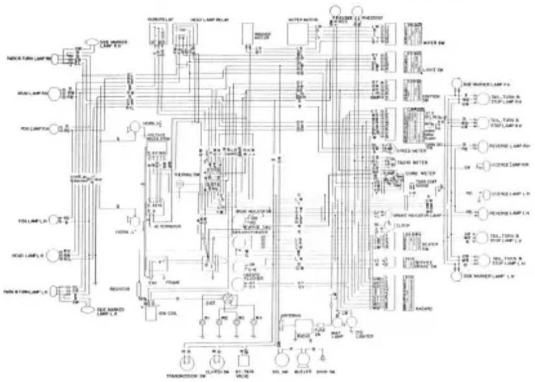
WIRING DIAGRAM
WIRING DIAGRAM (SPL311-U FOR USA AND CANADA)
flowchart
graph TD
    A["Head Lamp L1"] --> B["Resistor"]
    C["Head Lamp L2"] --> D["Resistor"]
    E["Head Lamp L3"] --> F["Resistor"]
    G["Head Lamp L4"] --> H["Resistor"]
    I["Resistor L5"] --> J["Resistor"]
    K["Resistor L6"] --> L["Resistor"]
    M["Resistor L7"] --> N["Resistor"]
    O["Resistor L8"] --> P["Resistor"]
    Q["Resistor L9"] --> R["Resistor"]
    S["Resistor L10"] --> T["Resistor"]
    U["Resistor L11"] --> V["Resistor"]
    W["Resistor L12"] --> X["Resistor"]
    Y["Resistor L13"] --> Z["Resistor"]
    AA["Resistor L14"] --> AB["Resistor"]
    AC["Resistor L15"] --> AD["Resistor"]
    AE["Resistor L16"] --> AF["Resistor"]
    AG["Resistor L17"] --> AH["Resistor"]
    AI["Resistor L18"] --> AJ["Resistor"]
    AK["Resistor L19"] --> AL["Resistor"]
    AM["Resistor L20"] --> AN["Resistor"]
    AO["Resistor L21"] --> AP["Resistor"]
    AQ["Resistor L22"] --> AR["Resistor"]
    AS["Resistor L23"] --> AT["Resistor"]
    AU["Resistor L24"] --> AV["Resistor"]
    AW["Resistor L25"] --> AX["Resistor"]
    AY["Head Lamp L1"] --> AZ["Ground"]
    BA["Head Lamp L2"] --> BB["Pump"]
    BC["Pump Lamp L3"] --> BD["Pump"]
    BE["Pump Lamp L4"] --> BF["Pump"]
    BG["Pump Lamp L5"] --> BH["Pump"]
    BI["Pump Lamp L6"] --> BJ["Pump"]
    BK["Pump Lamp L7"] --> BL["Pump"]
    BM["Pump Lamp L8"] --> BN["Pump"]
    BO["Pump Lamp L9"] --> BP["Pump"]
    BZ["Pump Lamp L10"] --> CA["Pump"]
    CB["Pump Lamp L11"] --> CC["Pump"]
    CD["Pump Lamp L12"] --> CE["Pump"]
    CF["Pump Lamp L13"] --> CG["Pump"]
    CH["Pump Lamp L14"] --> CI["Pump"]
    CJ["Pump Lamp L15"] --> CK["Pump"]
    CL["Pump Lamp L16"] --> CM["Pump"]
    CN["Pump Lamp L17"] --> CO["Pump"]
    CP["Pump Lamp L18"] --> CPB["Pump"]
    CS["Pump Lamp L19"] --> CSB["Pump"]
    CT["Pump Lamp L20"] --> CU["Pump"]
    CV["Pump Lamp L21"] --> CVB["Pump"]
    DD["Pump Lamp L22"] --> DV["Pump"]
    DV["Pump Lamp L23"] --> DVB["Pump"]
    DW["Pump Lamp L24"] --> DX["Pump"]
    DX["Pump Lamp L25"] --> DXB["Pump"]
    DB["Pump Lamp L26"] --> DCB["Pump"]
    DC["Pump Lamp L27"] --> DCB
    DDY["Pump Lamp L28"] --> DDYP["Pump"]
    DDYP["Pump Lamp L29"] --> DDYP
    DDYP["Pump Lamp L30"] --> DDYP
    DDYP["Pump Lamp L31"] --> DDYP
    DDYP["Pump Lamp L32"] --> DDYP
    DDYP["Pump Lamp L33"] --> DDYP
    DDYP["Pump Lamp L34"] --> DDYP
    DDYP["Pump Lamp L35"] --> DDYP
    DDYP["Pump Lamp L36"] --> DDYP
    DDYP["Pump Lamp L37"] --> DDYP
    DDYP["Pump Lamp L38"] --> DDYP
    DDYP["Pump Lamp L39"] --> DDYP
    DDYP["Pump Lamp L40"] --> DDYP
    DDYP["Pump Lamp L41"] --> DDYP
    DDYP["Pump Lamp L42"] --> DDYP
    DDYP["Pump Lamp L43"] --> DDYP
    DDYP["Pump Lamp L44"] --> DDYP
    DDYP["Pump Lamp L45"] --> DDYP
    DDYP["Pump Lamp L46"] --> DDYP
    DDYP["Pump Lamp L47"] --> DDYP
    DDYP["Pump Lamp L48"] --> DDYP
    DDYP["Pump Lamp L49"] --> DDYP
    DDYP["Pump Lamp L50"] --> DDYP
    DDYP["Pump Lamp L51"] --> DDYP
    DDYP["Pump Lamp L52"] --> DDYP
    DDYP["Pump Lamp L53"] --> DDYP
    DDYP["Pump Lamp L54"] --> DDYP
    DDYP["Pump Lamp L55"] --> DDYP
    DDYP["Pump Lamp L56"] --> DDYP
    DDYP["Pump Lamp L57"] --> DDYP
    DDYP["Pump Lamp L58"] --> DDYP
    DDYP["Pump Lamp L59"] --> DDYP
    DDYP["Pump Lamp L60"] --> DDYP
    DDYP["Pump Lamp L61"] --> DDYP
    DDYP["Pump Lamp L62"] --> DDYP
    DDYP["Pump Lamp L63"] --> DDYP
    DDYP["Pump Lamp L64"] --> DDYP
    DDYP["Pump Lamp L65"] --> DDYP
    DDYP["Pump Lamp L66"] --> DDYP
    DDYP["Pump Lamp L67"] --> DDYP
    DDYP["Pump Lamp L68"] --> DDYP
    DDYP["Pump Lamp L69"] --> DDYP
    DDYP["Pump Lamp L70"] --> DDYP
    DDYP["Pump Lamp L71"] --> DDYP
    DDYP["Pump Lamp L72"] --> DDYP
    DDYP["Pump Lamp L73"] --> DDYP
    DDYP["Pump Lamp L74"] --> DDYP
    DDYP["Pump Lamp L75"] --> DDYP
    DDYP["Pump Lamp L76"] --> DDYP
    DDYP["Pump Lamp L77"] --> DDYP
    DDYP["Pump Lamp L78"] --> DDYP
    DDYP["Pump Lamp L79"] --> DDYP
    DDYP["Pump Lamp L80"] --> DDYP
    DDYP["Pump Lamp L81"] --> DDYP
    DDYP["Pump Lamp L82"] --> DDYP
    DDYP["Pump Lamp L83"] --> DDYP
    DDYP["Pump Lamp L84"] --> DDYP
    DDYP["Pump Lamp L85"] --> DDYP
    DDYP["Pump Lamp L86"] --> DDYP
    DDYP["Pump Lamp L87"] --> DDYP
    DDYP["Pump Lamp L88"] --> DDYP
    DDYP["Pump Lamp L89"] --> DDYP
    DDYP["Pump Lamp L90"] --> DDYP
    DDYP["Pump Lamp L91"] --> DDYP
    DDYP["Pump Lamp L92"] --> DDYP
    DDYP["Pump Lamp L93"] --> DDYP
    DDYP["Pump Lamp L94"] --> DDYP
    DDYP["Pump Lamp L95"] --> DDYP
    DDYP["Pump Lamp L96"] --> DDYP
    DDYP["Pump Lamp L97"] --> DDYP
    DDYP["Pump Lamp L98"] --> DDYP
    DDYP["Pump Lamp L99"] --> DDYP
    DN["Ground"]
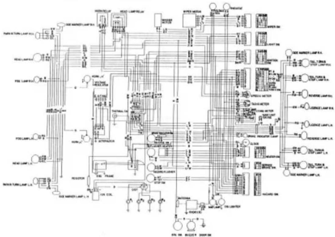
WIRING DIAGRAM (SRL311-U FOR USA AND CANADA)
WIRING DIAGRAM
flowchart
graph TD
    A["Power Turn Lamp L1"] --> B["Head Lamp"]
    B --> C["Power Turn Lamp L2"]
    C --> D["Head Lamp L3"]
    D --> E["Power Turn Lamp L4"]
    E --> F["Head Lamp L5"]
    F --> G["Power Turn Lamp L6"]
    G --> H["Power Turn Lamp L7"]
    H --> I["Power Turn Lamp L8"]
    I --> J["Power Turn Lamp L9"]
    J --> K["Power Turn Lamp L10"]
    K --> L["Power Turn Lamp L11"]
    L --> M["Power Turn Lamp L12"]
    M --> N["Power Turn Lamp L13"]
    N --> O["Power Turn Lamp L14"]
    O --> P["Power Turn Lamp L15"]
    P --> Q["Power Turn Lamp L16"]
    Q --> R["Power Turn Lamp L17"]
    R --> S["Power Turn Lamp L18"]
    S --> T["Power Turn Lamp L19"]
    T --> U["Power Turn Lamp L20"]
    U --> V["Power Turn Lamp L21"]
    V --> W["Power Turn Lamp L22"]
    W --> X["Power Turn Lamp L23"]
    X --> Y["Power Turn Lamp L24"]
    Y --> Z["Power Turn Lamp L25"]
    Z --> AA["Power Turn Lamp L26"]
    AA --> AB["Power Turn Lamp L27"]
    AB --> AC["Power Turn Lamp L28"]
    AC --> AD["Power Turn Lamp L29"]
    AD --> AE["Power Turn Lamp L30"]
    AE --> AF["Power Turn Lamp L31"]
    AF --> AG["Power Turn Lamp L32"]
    AG --> AH["Power Turn Lamp L33"]
    AH --> AI["Power Turn Lamp L34"]
    AI --> AJ["Power Turn Lamp L35"]
    AJ --> AK["Power Turn Lamp L36"]
    AK --> AL["Power Turn Lamp L37"]
    AL --> AM["Power Turn Lamp L38"]
    AM --> AN["Power Turn Lamp L39"]
    AN --> AO["Power Turn Lamp L40"]
    AO --> AP["Power Turn Lamp L41"]
    AP --> AQ["Power Turn Lamp L42"]
    AQ --> AR["Power Turn Lamp L43"]
    AR --> AS["Power Turn Lamp L44"]
    AS --> AT["Power Turn Lamp L45"]
    AT --> AU["Power Turn Lamp L46"]
    AU --> AV["Power Turn Lamp L47"]
    AV --> AW["Power Turn Lamp L48"]
    AW --> AX["Power Turn Lamp L49"]
    AX --> AY["Power Turn Lamp L50"]
    AY --> AZ["Power Turn Lamp L51"]
    AZ --> BA["Power Turn Lamp L52"]
    BA --> BB["Power Turn Lamp L53"]
    BB --> BC["Power Turn Lamp L54"]
    BC --> BD["Power Turn Lamp L55"]
    BD --> BE["Power Turn Lamp L56"]
    BE --> BF["Power Turn Lamp L57"]
    BF --> BG["Power Turn Lamp L58"]
    BG --> BH["Power Turn Lamp L59"]
    BH --> BI["Power Turn Lamp L60"]

Factory trained mechanics for complete Datum service
SPECIAL MAINTENANCE FOR EMISSION CONTROL SYSTEM
To reduce the amount of pollutants deposited in the atmosphere the Datsun is equipped with an emission control system. In order to ensure that this system continues to operate in an efficient manner it is imperative that the vehicle be taken to an authorized Datsun dealer at periodic intervals to have the required servicing carried out.
At the 600 mile and 2,000 mile service the Datsun dealer will check the operation of the system. Thereafter, in addition to the regular maintenance, the ignition timing and idling speed should be adjusted at 3,000 mile intervals. Every 12,000 miles the emission control system should receive a major service.
[Special tune-up data for emission control system]
SPL311-U 0° T.D.C. at 750 r.p.m.
SRL311-U 0° T.D.C. at 700 r.p.m.
natural_image
Vintage black-and-white photograph of a 19th-century convertible car (no visible text or symbols)SPECIAL MAINTENANCE FOR
EMISSION CONTROL SYSTEM
| MAINTENANCE FREQUENCY EVERY | CHEKING POINTS(Engines equipped with emission control system) | MAINTENANCE PERIODS | |||||||||||||||
| 1000 km(600 miles) | 3000 km(2000 miles) | 6000 km(4000 miles) | 10000 km(8000 miles) | 20000 km(9000 miles) | 30000 km(10000 miles) | 20000 km(15000 miles) | 30000 km(18000 miles) | 35000 km(21000 miles) | 40000 km(24000 miles) | ||||||||
| O | Check irrigation timing | ○ | ○ | ○ | ○ | ○ | ○ | ○ | ○ | ○ | ○ | ○ | |||||
| O | Check engine idling | ○ | ○ | ○ | ○ | ○ | ○ | ○ | ○ | ○ | ○ | ○ | |||||
| ○ | Engine major turn-up | ○ | ○ | ||||||||||||||
| O | Check spark plugs | ○ | ○ | ○ | ○ | ○ | ○ | ○ | ○ | ○ | ○ | ||||||
| ○ | Replace spark plugs | ○ | ○ | ||||||||||||||
| ○ | Check high tension cables | ○ | ○ | ||||||||||||||
| O | Check for fitting and wear of distributor breaker points | ○ | ○ | ○ | ○ | ○ | ○ | ○ | ○ | ○ | ○ | ||||||
| ○ | Replace distributor breaker points | ○ | ○ | ||||||||||||||
| ○ | Apply grease to distributor hose shaft | ○ | ○ | ||||||||||||||
| ○ | Apply grease to distributor cane and neck | ○ | ○ | ||||||||||||||
| Replace carbonate air cleaner element: Ruler to "A13. C11/AMR" | |||||||||||||||||
| ○ | Close pump air cleaner element | ○ | ○ | ○ | ○ | ||||||||||||
| ○ | Replace pump air cleaner element | ○ | ○ | ||||||||||||||
| ○ | Check for heater of heater and heater connections | ○ | ○ | ||||||||||||||
| ○ | Check for proper function of crucible ventilation control valves | ○ | ○ | ||||||||||||||
| ○ | Check for proper function of air pump | ○ | ○ | ||||||||||||||
| ○ | Check for proper function of wheel valve | ○ | ○ | ||||||||||||||
| ○ | Check for proper function of check valve | ○ | ○ | ||||||||||||||
| ○ | Check for proper function of anti-back fire valve | ○ | ○ | ||||||||||||||
| ○ | Check for leaks of air gallery and roads connection | ○ | ○ | ||||||||||||||
| ○ | Check for leaks of lanes and lock connections | ○ | ○ | ||||||||||||||
| ○ | Check for pump belt tendon | ○ | ○ | ||||||||||||||
| ○ | Check for proper function of electrical ports for exhaust outlet control system.(Throttle valve, Translubule outlets, Speed switch, Clutch switch, Acceleratorretraction, Stabilized valves and relaps) | ○ | ○ | ||||||||||||||
| ○ | Check for leads of liners, liners connectors and piping | ○ | ○ | ||||||||||||||
| ○ | Check for proper function of dam ggrade valve | ○ | ○ | ||||||||||||||

Printed in Japan Publication No. 10151 (40630200)
NISSAN MOTOR CO., LTD.