B100 - Empfänger Bryston - Kostenlose Bedienungsanleitung
Finden Sie kostenlos die Bedienungsanleitung des Geräts B100 Bryston als PDF.


Benutzerfragen zu B100 Bryston
0 Frage zu diesem Gerät. Beantworten Sie die, die Sie kennen, oder stellen Sie Ihre eigene.
Eine neue Frage zu diesem Gerät stellen
Laden Sie die Anleitung für Ihr Empfänger kostenlos im PDF-Format! Finden Sie Ihr Handbuch B100 - Bryston und nehmen Sie Ihr elektronisches Gerät wieder in die Hand. Auf dieser Seite sind alle Dokumente veröffentlicht, die für die Verwendung Ihres Geräts notwendig sind. B100 von der Marke Bryston.
BEDIENUNGSANLEITUNG B100 Bryston
BRYSTON
IMPORTANT SAFETY INSTRUCTIONS

The lightning flash with arrowhead symbol within an equilateral triangle, is intended to alert the user to the presence of un-insulated “dangerous voltage” within the product’s enclosure that may be of sufficient magnitude to constitute a risk of electric shock to persons.

The exclamation point within an equilateral triangle is intended to alert the user to the presence of important operating and maintenance (servicing) instructions in the literature accompanying the product.
- Read these instructions.
- Keep these instructions.
- Heed all warnings.
- Follow all instructions.
- Do not use this apparatus near water.
-
Clean only with dry cloth.
-
Do not block any ventilation openings. Install in accordance with the manufacturer's instructions.
-
Do not install near any heat sources such as radiators, heat registers, stoves, or other apparatus (including amplifiers) that produce heat.
-
Do not defeat the safety purpose of the polarized or grounding-type plug. A polarized plug has two blades with one wider than the other. A grounding type plug has two blades and a third grounding prong. The wide blade or the third prong are provided for your safety. If the provided plug does not fit into your outlet, consult an electrician for replacement of the obsolete outlet.
-
Protect the power cord from being walked on or pinched particularly at plugs, convenience receptacles, and the point where they exit from the apparatus.
-
Only use attachments/accessories specified by the manufacturer.
-
Use only with the cart, stand, tripod, bracket, or table specified by the manufacturer, or sold with the apparatus. When a cart is used use caution when moving the cart/apparatus combination to avoid injury from tip-over.
-
Unplug this apparatus during lightning storms or when unused for long periods of time.
-
Refer all servicing to qualified service personnel. Servicing is required when the apparatus has been damaged in any way, such as power-supply cord or plug is damaged, liquid has been spilled or objects have fallen into the apparatus, the apparatus has been exposed to rain or moisture, does not operate normally, or has been dropped.

WARNING: TO REDUCE THE RISK OF FIRE OR ELECTRIC SHOCK, DO NOT EXPOSE THIS APPARATUS TO RAIN OR MOISTURE.
DO NOT EXPOSE THIS EQUIPMENT TO DRIPPING OR SPLASHING AND ENSURE THAT NO OBJECTS FILLED WITH LIQUIDS, SUCH AS VASES, ARE PLACED ON THE EQUIPMENT.
TO COMPLETELY DISCONNECT THIS EQUIPMENT FROM THE AC MAINS, DISCONNECT THE POWER SUPPLY CORD PLUG FROM THE AC RECEPTACLE.
THE MAINS PLUG OF THE POWER SUPPLY CORD SHALL REMAIN READILY OPERABLE.
BRYSTON LIMITED WARRANTY
Bryston analog audio products are warranted to be free from manufacturing defects for twenty (20) years from the original date of manufacture. The warranty includes parts and labour.
Bryston Digital products and cables are warranted for five years from the original date of manufacture. The warranty includes parts and labour.
Bryston products having motorized moving parts, excluding motorized volume controls, are warranted for three years from the original date of manufacture. The warranty includes parts and labour.
Bryston will remedy the problem by repair or replacement, as we deem necessary, to restore the product to full performance. Bryston will pay return shipping costs for the full length of the specific product's warranty.
In the event of a defect or malfunction, contact Bryston's repair centers for return authorization. Products must be returned using original packaging material only. Packing material may be purchased from Bryston if necessary. This warranty is considered void if the defect, malfunction or failure of the product or any component part was caused by damage (not resulting from a defect or malfunction) or abuse while in the possession of the customer. Tampering by persons other than factory authorized service personnel or failure to fully comply with Bryston operating instructions voids the warranty.
This warranty gives you specific legal rights and you may also have other rights which may vary from province to province and country to country. As of 2006-02-22 Bryston will only warranty Bryston products purchased through authorized Bryston dealers. Bryston products with a date code of 0608 or higher (date code format is "yyww", where "yy" is the two least significant digits of the year and "ww" is the week of the year) must be accompanied by a copy of the bill-of-sale from a Bryston authorized dealer to qualify for warranty service. The warranty is transferable from the original owner to a subsequent owner as long as a copy of the bill-of-sale from the original authorized Bryston dealer accompanies the re-sale. The copy of the bill of sale to any subsequent owner need ONLY include the Name of the Bryston Authorized Dealer and the Model and Serial number of the Bryston product. The warranty will only be honored in the country of the original purchase unless otherwise pre-authorized by Bryston.
BRYSTON SERVICE in CANADA:
Postal address: P.O. BOX 2170, Stn. Main PETERBOROUGH, ONTARIO CANADA K9J 7Y4
Courier address: 677 NEAL DRIVE PETERBOROUGH, ONTARIO CANADA K9J 6X7
PHONE: 705-742-5325
FAX: 705-742-0882
E-mail: cdnser@bryston.com
BRYSTON SERVICE in the USA:
79 COVENTRY ST., Suite 5 NEWPORT, VERMONT U.S.A. 05855-2100
PHONE: 802-334-1201 FAX: 802-334-6658 E-mail: usaser@bryston.com
BRYSTON SERVICE outside Canada and the USA:
contact your local distributor or
CHECK OUR WEB SITE:
E-MAIL BRYSTON DIRECTLY:
FAX BRYSTON DIRECTLY:
PHONE BRYSTON DIRECTLY:
www.bryston.com
cdnser@bryston.com
01-705-742-0882
01-705-742-5325
TABLE OF CONTENTS
Page
• INTRODUCTION 1
- SETUP 1
• CONNECTIONS 1
• INPUTS & OUTPUTS 1-2
• LED STATUS INDICATORS....2
• REMOTE POWER CONTROL....3
• PROGRAMMING THE 12V TRIGGER 3
• HAND-HELD IR REMOTE CONTROL 4
• PROGRAMMING THE IR REMOTE CONTROL 4
- SENDING CODES to the B100 via the IR REMOTE CONTROL 4
• WIRED RS232 REMOTE CONTROL 4
• PASS-THROUGH MODE 5
• DIGITAL-TO-ANALOG CONVERTER OPTION 5
• MOVING-MAGNET PHONO STAGE OPTION 5
- SPECIFICATIONS....6
• FRONT & REAR PANEL DETAILS 7
• EXTERNAL DIMENSIONS & RECOMMENDED CLEARANCE ENVELOPE 8
BRYSTON
INTRODUCTION
Thank you for purchasing a Bryston B100 integrated amplifier. We are confident it will provide you with many years of musical enjoyment. We would welcome any suggestions or comments you may have regarding the operation of your Bryston amplifier.
In the unlikely event that your amplifier may require service Bryston recommends that you retain the original shipping box and packaging material for future use if required.
SETUP RECOMMENDATIONS
You may place your B100 integrated amplifier in any convenient location. If you have purchased the optional infra-red remote control, make sure you position the amplifier to maintain a direct line-of-sight between the hand-held remote and the IR sensor eye located on the front panel. If plugged in the B100 will remain in standby indicated by the RED power LED on the front panel.
The amplifier is powered up by engaging the power button located on the front panel of the B100 or by depressing the POWER button on the hand held remote control unit.. The B100 will power-up momentarily with mute engaged, indicated by the mute LED turning red on the front panel; it will then turn off within a few seconds. The POWER LED will stay lit green indicating normal operation.
CONNECTIONS
MAINS POWER INLET:
Mains power is connected to the B100 through an IEC-C14 power inlet on the rear panel. This inlet mates with an IEC-C14 connector. Use only an approved power cord for your location. Before connecting or disconnecting the power cord, make sure that the unit is powered off.
POWER CONDITIONERS:
Bryston urges caution in choosing a power conditioner for your audio/video system. Large power amplifiers can draw very substantial current from the wall plug, and many so-called power conditioners can in fact hinder the supply of current by inserting resistances in series with the line cord. However, there are now power conditioners that can reduce or eliminate RF and 'hash' from the AC supply and may actually improve current delivery to your system. This type of power conditioner (exemplified by 'TORUS' Power Conditioners) uses the energy storage in a large toroidal transformer to provide high instantaneous power and reduce the substantial AC output resistance of the wall socket and house wiring. This resistance can be in the range of 0.5 to 1 Ohm and is typically reduced to only a few milliOhms by the Power Conditioner. That in turn considerably reduces Voltage drop in the power line on high current surges and quite substantially increases the stability of the power line improving audio (and video) focus, precision and clarity.
LOUDSPEAKERS:
Connect your loudspeakers, ensuring that the positive (red) and ground (black) terminals (gold-plated 5-way binding posts) on the Bryston B100 integrated amplifier are connected to the positive and ground terminals on your loudspeakers. Make certain the left and right speaker outputs on the amplifier are connected to your appropriate left and right loudspeakers.
SEPARATE PRE-AMP OUT & POWER AMP IN JACKS:
These two pair of RCA jacks allow for the independent use of the stereo amplifier section within a multi-channel audio or video system. On the rear panel there are connections labeled 'PRE AMP OUT' (preamplifier output) and 'POWER AMP IN' (power amplifier input) along with two slide switches (one per channel) labeled "Separate/Connect". This feature allows you to "separate or connect" the preamplifier section of the B100 from the power amplifier section thus producing a separate stereo preamp and separate stereo power amplifier.
WIRED (SERIAL DATA) REMOTE CONTROL:
There is one RS-232, one AUX IR input and two 12 volt trigger output connections as well. The RS-232 is bidirectional and allows for future software downloads from the Bryston website. It also interfaces with control systems such as Crestron and AMX.
CHASSIS GROUND:
A chassis ground thumb screw terminal is provided on the rear panel.
12 VOLT TRIGGER CONNECTOR:
These 12Vdc control outputs allow the B100 to exert on/off control over compatible equipment. See “REMOTE POWER CONTROL” for more information..
LINE LEVEL ANALOG AUDIO INPUTS :
The Bryston B100 integrated amplifier comes equipped with 8 pairs of gold plated analog RCA input connectors: TV, CD, AUX-1/PHONO, AUX-2/SPDIF, VIDEO, TUNER, RECORD IN and POWER AMP IN. All have and input impedance of 50K ohms
- POWER AMP IN is normally connected, internally, to PRE AMP OUT via the CONNECTED/SEPARATE slide switch located on the rear panel. When this switch is in the SEPARATE position, however, any line level audio input can be used at the POWER AMP INPUT jacks to drive the amplifier.
- In B100-DA models the AUX2 (D1/D2) input jacks accept only SPDIF PCM bit streams. They do NOT accept analog audio input signals.
- In B100-P models, which are equipped with a moving-magnet phono equalization module, the inputs labeled AUX1/PHONO accept moving magnet phono cartridge inputs. These inputs are NOT line level inputs in the B100-P and cannot be used as such.
LINE LEVEL ANALOG AUDIO OUTPUTS :
The Bryston B100 integrated amplifier comes equipped with 2 pairs of gold plated analog RCA jacks for outputs: PREAMP OUT and RECORD OUT.
- PREAMP OUT is normally connected, internally, via the CONNECTED/SEPARATE switch, to POWER AMP IN
- RECORD OUT output is not affected by volume, balance or mute controls.
DIGITAL AUDIO INPUTS:
In the B100-DA model, which contains a stereo D/A converter module, there are 4 digital audio inputs available.
TOSLINK: Two TOSLINK optical inputs are selected by pressing the D3 (TOSLINK-1) or D4 (TOSLINK-2) buttons on the front panel (when in digital mode) or on the handheld remote.
SPDIF: Two SPDIF coaxial inputs can be connected to the B100-DA using the RCA input jacks labeled D1 and D2. To select these inputs first place the unit in digital mode by pressing the DIGITAL ▶ Select button on the front panel (or the A/D button on the handheld remote) and then press the D1 or D2 button on the front panel or on the remote). When the green LED above the font panel DIGITAL ▶ SELECT switch button in ON concurrently with either the D1 (CD), D2 (TUNER), D3 (TV) or D4 (VIDEO) LEDs, then digital mode is engaged.
Note: When returning to an input the mode previously used with that input will be automatically re-selected. See also the DIGITAL-to-ANALOG CONVERTER OPTION section for more information.
HEADPHONE JACK:
There is a quarter inch headphone output jack available on the front panel of the Bryston B100 integrated amplifier. The headphone output is driven directly from the preamplifier section utilizing separate headphone buffers. Inserting the headphone jack mutes the loudspeakers automatically (indicated by the mute LED on the front panel turning red). The B100 PREAMP OUT is also muted.
You can adjust the volume setting of the headphones by using the volume control on the front of the B100 integrated amplifier. You may also utilize the remote control unit to adjust headphone volume. The headphones cannot be muted with the remote control unit or the front panel Mute. Only headphones with impedances greater than 50 ohms should be used.
AUXILIARY IR INPUT:
This mono 1/8" (3mm) phone jack allows a direct connection to equipment whose remote control system provides an output from their infra-red LED drive circuit. The signal connected to this jack, which is expected to
be a 5 volt logic level, should be ≥2.5Vdc and ≤10Vdc . The tip of the phone jack is positive (+) and the ring is negative (-).
LED STATUS INDICATORS
CLIPPING: This LED (light emitting diode) will flash RED when the output waveform is clipped indicating an overload condition.
MUTE: Lights RED to indicate the outputs are muted..
POWER: GREEN indicates normal operation
RED indicates Standby
Blinking RED/GREEN a fault or thermal overload problem in the unit.
ANALOG ▶ Aux2 / DIGITAL ▶ Select:
In B100-DA models: when this LED is illuminated green concurrently with either D1, D2, D3 or D4 LEDs, it indicates that the digital inputs D1 (SPDIF), D2 (SPDIF), D3 (TOSLINK) or D4 (TOSLINK) have been selected.
In B100 & B100-P models: when illuminated green this LED indicates that the line level analog audio input AUX-2 has been selected.
AUX1, CD, TUNER, TV/SAT VIDEO & RECORD:
One of these input source LEDs will light green to Indicate the active input. In digital mode these LEDs will light RED if the bit stream is either absent or unacceptable.
BALANCE
When the left/right signal balance is being shifted one of these LEDs will light to indicate which channel is being attenuated. Balance can be adjusted in 1dB increments to up to -6dB in either direction. Stepping past -6dB in either direction will mute that channel fully and the LED for that channel will turn red.
When both LEDs are on (red), PASS THROUGH mode is indicated. (See "Pass Through Mode" on page 4)
Note: In some markets the LED indicators, which are normally red/green, may be red/blue instead. When red/blue LEDs are supplied green is replaced with blue and orange is replaced with magenta in the above descriptions.
REMOTE POWER CONTROL \~ 12 VOLT TRIGGER CONNECTOR
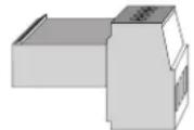
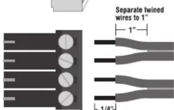
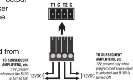
Two trigger outputs are provided. A 12Vdc signal is placed across the T1 and C pins of the 12V TRIGGERS connector whenever the unit is fully powered up. Then the unit goes into standby this voltage is removed.
text_image
Separate twine d wires to 1" 1"Bryston part number CO-110A-11104
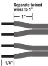
Strip wires 1/4"
A 12Vdc signal will be placed across the other pair of 12V TRIGGER output pins (T2) whenever a certain user programmed input is selected as the source input (see below for programming instructions). When any other input source is selected the 12Vdc control voltage will be removed from these pins. Please note that C means “common” here and both C pins are electrically connected and identical.
B100-SST Power Amplifier
REMOTE TRIGGER IN/OUT CONNECTOR
text_image
Output Power e T1 C T2 C d from TO SUBSEQUENT AMPLIFIERS, etc. 12V present whenever the B100 is turned ON. 12VDC{ }12VDC TO SUBSEQUENT AMPLIFIERS, etc. 12V present only when programmed source input is selected and B100 is turned ON.PROGRAMMING THE "T2" 12V TRIGGER OUTPUT
By default the T2 triggered output is inactive. To program this output to become active, whereupon a control voltage of 12Vdc will appear across T2 & C terminals whenever a specific source is selected, use the handheld remote control as follows:
- Select the source that you want to coincide with T2 going active.
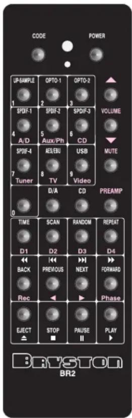
- While pointing the remote control at the B100, press the CODE button, followed by the three digit code "247" using the keys numbered 1 through 0 in the illustration at the left. On your remote control these keys, or buttons, are labeled AUX/PH (2), TUNER (4), D1 (7).
- The three digit code should be entered within a few seconds of pressing CODE button or the unit will automatically return to normal operation.
- To clear the T2 trigger output, press the CODE button followed by the 3 digit code "248": AUX/PH (2), TUNER (4), D2 (8).
text_image
CODE POWER UP-SAMPLE OPTO-1 OPTO-2 VOLUME 1 2 3 4 SPDIF-1 SPDIF-2 SPDIF-3 A/D 5 Aux/Ph 6 CD 7 SPDIF-4 AES/EBU USB Tuner 8 TV 9 Video 0 D/A CD PREAMP TIME SCAN RANDOM REPEAT D1 D2 D3 D4 BACK PREVIOUS NEXT FORWARD Rec Phase EJECT STOP PAUSE PLAY DRYSTON BR2HAND-HELD INFRA-RED REMOTE CONTROL
A full function hand-held infra-red remote control is available for the B100 integrated amplifier as an extra-cost option. The hand held remote unit is powered by two “AAA” batteries. To change the battery remove the bottom cover plate by removing the four Philips screws on the rear of the remote unit. Ensure that the batteries are correctly oriented and properly seated in the battery holder.
The BR2remote is a full function remote allowing selection of all sources, volume up or down (the volume control is a motor-driven design), mute ,left/right balance, power on, and discrete code entry.
We recommend maintaining a direct line-of-sight between the hand held remote unit and the front of the B100 to ensure the most efficient operation of the remote features.
PROGRAMMING THE HANDHELD REMOTE CONTROL
The automatic motion-sensing backlight function in the handheld infra-red remote control unit can be disabled by entering the 3 digit code "792" as follows:
1) Press and hold the CODE button for 5 seconds. Release when the LED flashes red.
2) After the LED stops flashing, enter the 3 digit code "792" by pressing the buttons D1, D3 then AUX/PH (see illustration on page 3)
3) To re-enable the motion-sensing backlight function, repeat steps 1 and 2 above
To completely disable the backlight, enter the 3 digit code "797" as follows:
1) Press and hold the CODE button for 5 seconds. Release when the LED flashes red.
2) After the LED stops flashing, enter the 3 digit code "797" by pressing the buttons D1, D3 then D1 (see illustration on page 3)
3) To re-enable the backlight repeat steps 1 and 2 above
SENDING CODES TO THE B100 VIA THE IR REMOTE CONTROL
Press the CODE button on the remote control (the red LED will light) and then enter the 3 digit code, as listed in the "Wired RS232 Remote Control" section below. The LED will flash to confirm transmission and then extinguish.
WIRED RS232 REMOTE CONTROL
Using the DB9-female connector at the rear of the unit, the B100 can receive commands via a null modem cable at 9600 baud, 8 data bits, no parity and 1 stop bit (9600,8,N,1). Valid commands will return the “>” character indicating that the unit is ready to receive a new command. An invalid command will return the “!” character. These serial data commands are as follows:
| 000 - power off | 015 - power on/off toggle | 081 - select digital source 1 (D1) |
| 001 - select analog source 1 (A/D) | 019 - balance left | 082 - select digital source 2 (D2) |
| 002 - select analog source 2 (AUX/PH) | 020 - balance right | 083 - select digital source 3 (D3) |
| 003 - select analog source 3 (CD) | 029 - power on | 084 - select digital source 4 (D4) |
| 004 - select analog source 4 (TUNER) | 058 - mute on | 245 - set/reset Pass Through mode |
| 005 - select analog source 5 (TV) | 059 - mute off | 247 - Set Trigger 2 for current source |
| 006 - select analog source 6 (VIDEO) | 061 - record monitor toggle | 248 - Clear Trigger 2 for current source |
| 007 - volume up | 062 - record monitor on | 255 - System reset; restore defaults |
| 008 - volume down | 063 - record monitor off |
BRYSTON
PASS THROUGH MODE
PASS THROUGH mode sets the pre-amp gain to 1 (unity gain) and locks out the volume & balance controls for any single analog audio source. For example, if the Front Left and Front Right outputs of a home theater surround sound processor were connected to the TV input of the B100, and then PASS THROUGH was engaged then whenever TV input is selected the volume and balance controls would be locked at unity gain. If other inputs were subsequently selected, volume and balance controls return to normal operation for those other input sources. Only the TV inputs would be locked at unity gain. PASS THROUGH mode, therefore, can only be assigned to one input at a time, but that input can be any one of the analog audio inputs. The power amplifier stage is not affected by PASS THROUGH mode. PASS THROUGH mode can only be set (or reset) by sending the 3 digit code "245" to the B100 either from the handheld IR remote control or via the RS232 serial data input. See "Sending Codes to the B100 via the IR Handheld Remote Control" & "Wired RS232 Remote Control". To reassign PASS THROUGH mode to a different input source simply select the desired input and re-send the "245" code to the B100. To turn the deactivate PASS THORUGH mode, select the current Pass Through input and then send the "245" code to the B100. The "245" toggles PASS THROUGH mode on and off.
DIGITAL-TO-ANALOG (D/A) CONVERTER OPTION
The B100-DA comes equipped with stereo Digital-to-Analog converter (D/A or DAC) module. This module is also retrofittable to standard B100 units.
A unique feature of the B100-DA is its ability to utilize up to four independent digital sources (two SPDIF and two TOSLINK). These four digital inputs can be accessed by selecting D1, D2, D3 and D4 sources with the DAC feature enabled (by pressing the DIGITAL ▶ Select button on the left end of the front panel).
Activate the DAC feature by pressing the DIGITAL ▶ Select (AUX 2) button on the left side of the front panel (or A/D on the remote). The LED below the DIGITAL ▶ Select button will turn Green. Pressing any of the following four buttons will cause their LEDs to light green, as well, to indicate a PCM digital source is present and connected properly.
- SPDIF 1 is accessed by selecting D1 on the front panel or the remote.
- SPDIF 2 is accessed by selecting D2 on the front panel or the remote.
• Optical 1 is accessed by selecting D3 on the front panel or the remote.
• Optical 2 is accessed by selecting D4 on the front panel or the remote.
The source LED's will turn GREEN when a PCM digital bit stream is present. If there is no bit stream available or an incorrect bit stream (NON-PCM) the LED will turn RED.
You may re-select Analog by simply depressing the DIGITAL ▶ Select (AUX 2) button once more and the LED will extinguish.
All of the above functions are available from the hand held remote control as well.
MOVING-MAGNET PHONO STAGE OPTION
The B100-P contains a moving magnet phono stage. The Phono Stage is modular and can be added to the standard B100 model later if required by your Bryston dealer.
Bryston's MM Phono section features state-of-the-art accuracy in equalization, extremely low noise and distortion, and provides headroom margins sufficient to prevent overload from any known phono source. To access the Phono section simply plug your left/right turntable interconnect leads into the left/right AUX-1/PHONO inputs on the rear panel of the B100 and press the AUX-1/PHONO button on the front panel. The AUX-1/PHONO LED will turn green. If your turntable provides a separate ground lead, system noise may be minimized by connecting it to the ground lug in the center of the rear panel.
POWER AMPLIFIER SECTION:
Power Output: 100 watts per channel into 8Ω 180 watts per channel into 4Ω
Input Impedance: 50K ohms single ended
Sensitivity: 1v = 100 Watts into 8 ohms (gain = 28.28 or 29dB)
Distortion: THD+noise: < 0.005% 20Hz to 20kHz at 100 watts into 8 ohms, IMD: < 0.010% 60Hz + 7KHz mixed 4:1
Noise: >108dB below rated output (with 20Hz to 22KHz bandpass filter)
Slew Rate: >60 volts per microsecond
Power Bandwidth: <1 Hz to over 100 kHz
Damping Factor: Over 500 at 20 Hz, ref. 8 ohms
Power consumption: idle 30va, maximum power 600va
Heat load: idle 100 btu/hr., max power 288 btu/hr
PREAMPLIFIER SECTION:
Frequency response: 20Hz to 20KHz, ±.05dB
IMD or THD: <.007%
High Level Sensitivity: 500mV
Noise: 100dB @ 20Hz to 20KHz (ref: 1V input)
GENERAL:
Dimensions: 17" or 19" wide X 4.55" high X 14" deep (433 or 483mm X 116mm X 353mm)
Weight: approx. 30 lbs (13.6kg.)
flowchart
graph TD
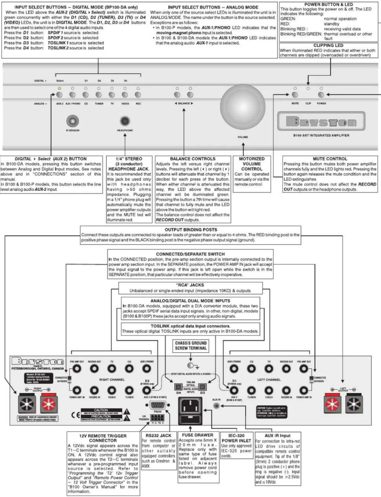
A["INPUT SELECT BUTTONS ~ DIGITAL MODE (BP100-DA only)<br>When the LED above the AUX-2 (DIGITAL) > Select switch is illuminated green concurrently with either the D1 (CD), D2 (TUNER), D3 (TV) or D4 (VIDEO) LEDs, the unit is in DIGITAL MODE. The D1, D2, D3 or D4 buttons are then used to select one of the 4 digital audio inputs.<br>Press the D1 button: SPDIF 1 source is selected<br>Press the D2 button: SPDIF 2 source is selected<br>Press the D3 button: TOSLINK 1 source is selected<br>Press the D4 button: TOSLINK 2 source is selected"] --> B["ANALOG"]
B --> C["Select"]
C --> D["D1"]
C --> E["D2"]
C --> F["D3"]
C --> G["D4"]
B --> H["AUX 2 AUX 1 PHONO CD TUNER TV VIDEO REC"]
B --> I["IN SENSOR"]
B --> J["HEADPHONE"]
B --> K["1/4" STEREO (3 conductor) HEADPHONE JACK. It is recommended that this jack be used only with headphones having >50 ohms impedance. Plugging in a 1/4" phone plug will automatically mute the power amplifier outputs and the MUTE led will illuminate red."]
L["INPUT SELECT BUTTONS ~ ANALOG MODE<br>When only one of the source select LEDs is illuminated the unit is in ANALOG MODE. The name under the button is the source selected. Exceptions are as follows:<br>• In B100-P models, the AUX-1/PHONO LED indicates that the moving-magnet phono input is selected.<br>• In B100 & B100-DA models the AUX-1/PHONO LED indicates that the analog audio AUX-1 input is selected."] --> M["MUTE CLIP POWER"]
M --> N["B100-SST INTEGRATED AMPLIFIER"]
O["POWER BUTTON & LED<br>This button toggles the power on & off. The LED indicates the following:<br>GREEN: normal operation<br>RED: standby<br>Blinking RED : receiving valid data<br>Blinking RED/GREEN: thermal overload or other fault"] --> P["CLIPPING LED<br>When illuminated RED indicates that either or both channels are clipped (overloaded or overdriven)"]
Q["OUTPUT BINDING POSTS<br>Connect these outputs are connected to speaker loads of greater than or equal to 4 ohms. The RED binding post is the positive phase signal and the BLACK binding post is the negative phase output signal (ground)."] --> R["CONNECTED/SEPARATE SWITCH<br>In the CONNECTED position, the pre-amp section output is internally connected to the power amp section input. In the SEPARATE position, the POWER AMP IN jack will accept the input signal to the power amp. If this jack is left open while the switch is in the SEPARATE position, that particular channel will be effectively inoperative."]
S[""RCA" JACKS<br>Unbalanced or single-ended input (impedance 10KΩ) & outputs"] --> T["ANALOG/DIGITAL DUAL MODE INPUTS<br>In B100-DA models, equipped with a D/A converter module, these two jacks accept SPDIF serial data input signals. In other, non-digital, models (B100 & B100P) these jacks accept only analog audio signals."] --> U["TOSLINK optical data Input connectors.<br>These optical digital TOSLINK inputs are only active in B100-DA models."] --> V["CHASSIS GROUND SCREW TERMINAL"]
W["12V REMOTE TRIGGER CONNECTOR<br>A 12Vdc signal appears across the T1-C terminals whenever the B100 is ON, A 12Vdc control signal also appears across the T2-C terminals whenever a pre-programmed input source is selected. Refer to "Programming the 'T2' 12v Trigger Output" and "Remote Power Control ~ 12 Volt Trigger Connector" in the "B100 Owner's Manual" for more information."] --> X["RS232 JACK<br>For remote control from computer or other suitably equipped controllers such as Crestron & AMX"] --> Y["FUSE DRAWER<br>Accepts one 5mm X 20 mm fuse. Replace only with same type of fuse listed on adjacent label. Always remove power cord before opening fuse drawer."] --> Z["IEC-320 POWER INLET<br>Use only approved IEC-320 power cords."] --> AA["AUX IR INPUT<br>For connection to infra-red LED drive circuits of compatible remote control equipment. Tip of the 1/8" (3mm) 2 conductor phone plug is positive (+) and the ring is negative (-). Input signal should be ≥2.5Vdc and ≤10Vdc"]
B100 INTEGRATED AMPLIFIER
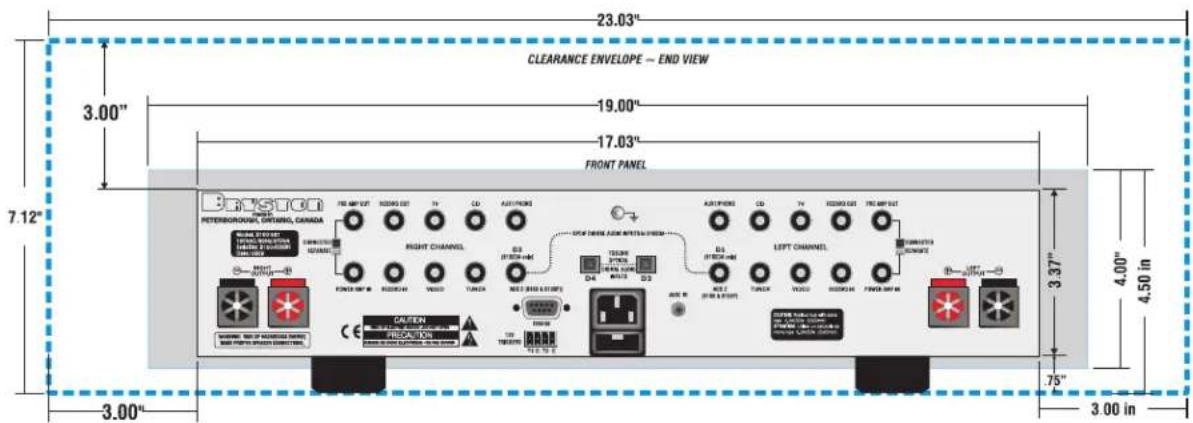
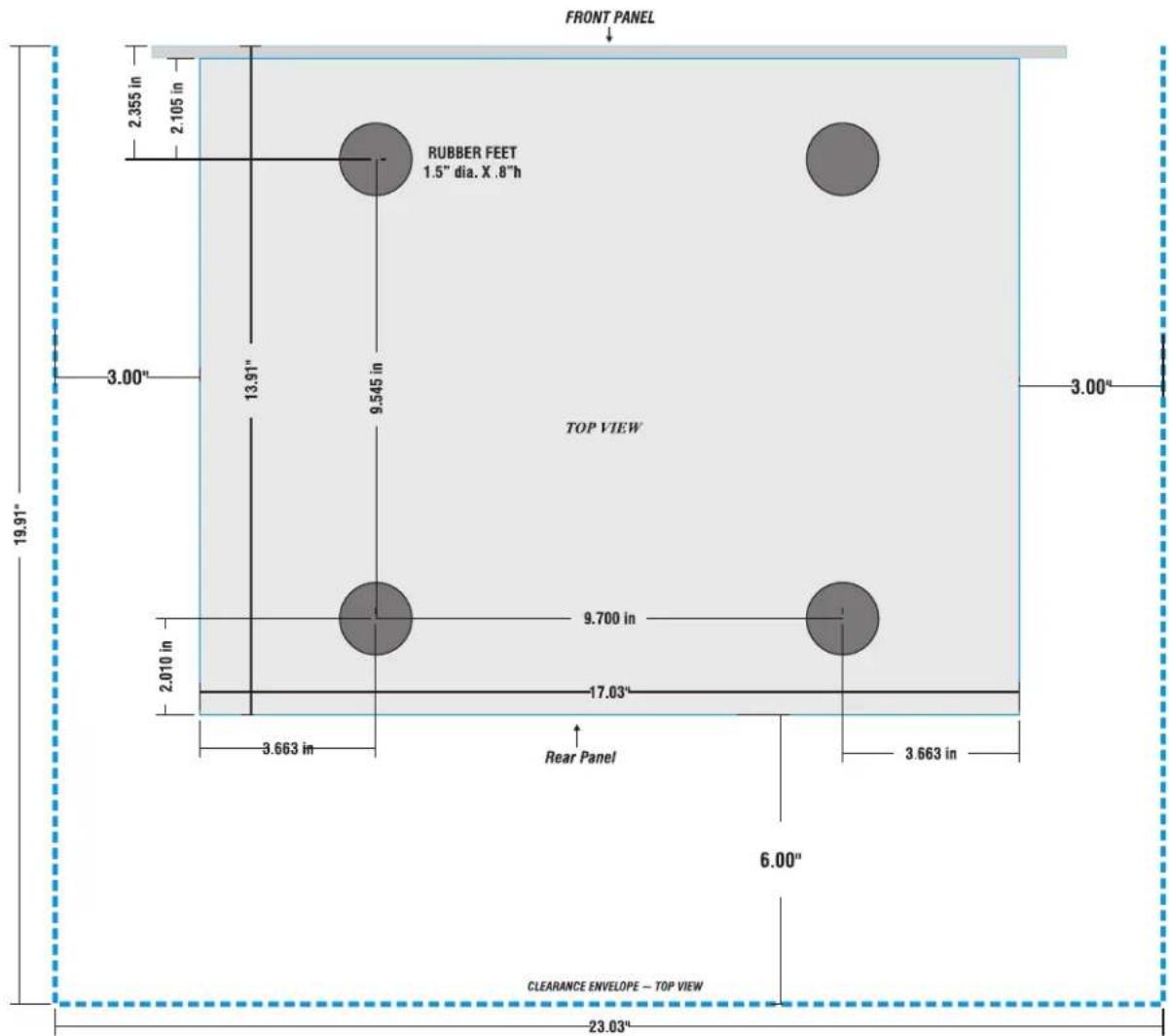
EXTERNAL DIMENSIONS & CLEARANCE ENVELOPE
text_image
FRONT PANEL 2.355 in 2.105 in RUBBER FEET 1.5" dia. X .8"h 9.545 in 3.00" 13.91" 9.700 in 2.010 in 17.03" 3.663 in Rear Panel 3.663 in 6.00" CLEARANCE ENVELOPE - TOP VIEW 23.03" TOP VIEW 19.91" 3.00"