Delta - Fahrradcomputer Ascent - Kostenlose Bedienungsanleitung
Finden Sie kostenlos die Bedienungsanleitung des Geräts Delta Ascent als PDF.


| Produkttyp | Drahtloser Fahrradcomputer |
| Modell | Delta Wireless |
| Marke | Ascent |
| Kategorie | Fahrradcomputer |
| Display | LCD-Digitalanzeige |
| Geschwindigkeitsanzeige | Bis 100 M/H oder K/H, Auflösung 0,1 |
| Funktionen | Aktuelle Geschwindigkeit, Durchschnittsgeschwindigkeit, Maximalgeschwindigkeit, Geschwindigkeitsvergleich (▲/▼), Uhrzeit (12/24h), automatischer Fahrtzeitmesser (ATM), Tageskilometer (DST), Gesamtkilometer (ODO) |
| Radgrößenprogrammierung | über Radumfang (mm), zwei einstellbare Größen (1 und 2) |
| Odometer programmierbar | Ja, für jede Radgröße separat |
| Stromversorgung Computer | 1x CR2032 3V Knopfzelle |
| Stromversorgung Sensor | 1x CR2032 3V Knopfzelle |
| Batterielebensdauer | 1–2 Jahre unter Normalbedingungen |
| Kabellose Reichweite | 24 Zoll (60 cm) |
| Automatische Schlaffunktion | Nach 5 Minuten Inaktivität |
| Montage | Lenkerhalterung mit Kabelbindern, Magnetsensor am Speichen |
| Magnet-Sensor-Abstand | Maximal 3 mm |
| Reset-Möglichkeiten | Teilreset (AVG/MAX, DST, ATM einzeln) und Globalreset (CLEAR-Taste) |
| Niedriger Batterieanzeige | Symbol im Display |
| Störanfälligkeit | Möglich durch elektromagnetische Felder (Hochspannungsleitungen, Motoren, andere Funkgeräte) |
| Lieferumfang | Computer, Sensor/Transmitter, Lenkerhalterung, Kabelbinder, Magnetsensor |
| Wartung | Regelmäßiger Batteriewechsel, Reinigung mit weichem, trockenem Tuch |
Häufig gestellte Fragen - Delta Ascent
Benutzerfragen zu Delta Ascent
0 Frage zu diesem Gerät. Beantworten Sie die, die Sie kennen, oder stellen Sie Ihre eigene.
Eine neue Frage zu diesem Gerät stellen
Laden Sie die Anleitung für Ihr Fahrradcomputer kostenlos im PDF-Format! Finden Sie Ihr Handbuch Delta - Ascent und nehmen Sie Ihr elektronisches Gerät wieder in die Hand. Auf dieser Seite sind alle Dokumente veröffentlicht, die für die Verwendung Ihres Geräts notwendig sind. Delta von der Marke Ascent.
BEDIENUNGSANLEITUNG Delta Ascent
Delta Wireless
INTRODUCTION
Thank you for your purchase of an Ascent™ cycle computer. With all the features that a professional rider needs to keep track of a ride, the Ascent Delta Wireless is the perfect accessory for any cyclist. The added convenience of wireless transmission makes installation simple!
BATTERY INSTALLATION
To help you get started quickly, the computer and transmitter batteries have been installed at the factory. Under normal use the batteries should last one to two years. The Delta Wireless uses a 3V CR2032 button cell battery (available at most drug stores or electronic shops) in both the computer and the sensor/transmitter.
NOTE: Most problems that occur with cyclocomputers are caused by dead or weak batteries.
Should you need to replace the batteries, follow the steps below.
COMPUTER HEAD
- NOTE: During a battery change, all data will be cleared from memory. Make a note of your current wheel size settings and cumulative odometer mileage before replacing the battery so you can reprogram these values once the new battery is installed (see "Program Wheel Size" and "Program the Odometer").
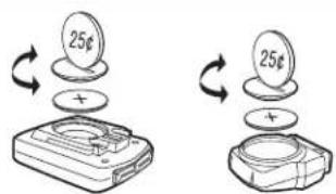
- Remove the battery cover from the underside of the computer using a coin. See Figure 1. Remove the old battery and dispose of properly.
Fig 1
text_image
25¢ + 25¢- Install a fresh battery with the positive (+) side facing the battery cover.
- Reinstall the battery cover securely, making sure the rubber O-ring is still in place and does not get pinched or distorted.
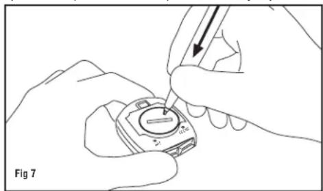
- If for some reason the screen is blank or shows an irregular display after a battery change, depress the CLEAR button on the underside of the computer head. See Figure 7.
SENSOR/TRANSMITTER
- Remove the battery cover from the back of the transmitter using a coin. See Figure 1. Remove the old battery and dispose of properly.
- Install a fresh battery with the positive (+) side facing the battery cover.
- Reinstall the battery cover securely, making sure that the rubber O-ring is still in place and does not get pinched or distorted.
COMPUTER FUNCTIONS
The Ascent Delta Wireless offers the following functions, which can be accessed by pressing the LEFT button.
CURRENT SPEED (M/H or K/H)
Displays current speed, up to 100 M/H or K/H. Accurate to 0.1M/H or K/H. Always displayed at the top of the screen.
AVERAGE SPEED (AVG)
Calculates average speed based on ride time (ATM) & trip distance (DST).
MAXIMUM SPEED (MAX)
Displays highest speed attained during a ride (or since last reset), up to 100 M/H or K/H.
SPEED COMPARISON (▲ or ▼)
Compares current speed to average speed. As you ride, a (▲) or (▼) will appear next to current speed to indicate whether your current speed is above (▲) or below (▼) your average speed. This function is automatic, requires no programming and cannot be disabled.
CLOCK (CLK)
Displays time of day in a 12 hour or 24 hour format.
AUTOMATIC RIDE TIMER (ATM)
Auto start/stop timer is activated by front wheel movement and records actual ride time up to 24:00:00.
TRIP DISTANCE (DST)
Displays distance traveled during current ride (or since last reset), up to 9999.9 miles or kilometers.
ODOMETER (ODO)
Displays cumulative ride distance, up to 99,999.9 miles or kilometers.
DUAL WHEEL SIZE SETTINGS (1) or (2)
Wheel circumference is used to calculate speed and distance. The Delta Wireless includes two wheel size settings (1 and 2), which allow you to use the computer on two bikes with different wheel sizes (e.g. your road bike and mountain bike).
AUTO SLEEP
To prolong battery life, the Delta Wireless will automatically enter "sleep" mode after 5 minutes of non-use. In sleep mode, only the time of day will be displayed. The computer will automatically exit sleep mode as soon as any button is pressed.
DETERMINE WHEEL SIZE
The Delta Wireless uses wheel circumference (measured in millimeters) to calculate speed and distance. Before you can program the computer you must calculate wheel circumference using one of the three methods below.
- Select size from chart (least accurate): Use the chart below to find the circumference for your tire size. The chart lists the programming sizes for some of the most popular tire sizes currently in use. These numbers are estimations which may not precisely match the circumference of your wheel, due to variations in tire size between brands and models.
| TIRE SIZE | CIRCUMFERENCE | TIRE SIZE | CIRCUMFERENCE |
| 16 x 1.75 | 1272 | 27 × 1^1/4 | 2199 |
| 20 x 1.75 | 1590 | 28 x 1.5 | 2224 |
| 24 × 1^3/8 | 1948 | 28 x 1.75 | 2268 |
| 24 x 1.75 | 1907 | 28 × 1^1/2 | 2265 |
| 26 x 0.75 | 1954 | 28 × 1^3/8 | 2205 |
| 26 x 1.0 | 1973 | 700 x 18c | 2102 |
| 26 × 1^3/8 | 2105 | 700 x 20c | 2114 |
| 26 x 1.5 | 2026 | 700 x 23c | 2133 |
| 26 x 1.6 | 2051 | 700 x 25c | 2146 |
| 26 x 1.75 | 2070 | 700 x 28c | 2149 |
| 26 x 1.9 | 2089 | 700 x 32c | 2174 |
| 26 x 2 | 2114 | 700 x 37c | 2205 |
| 26 × 2^1/8 | 2133 | 700 x 40c | 2224 |
- Measure wheel diameter (more accurate): Measure your wheel diameter (including wheel and tire) in millimeters (1 inch = 25.4mm) and multiply by 3.1416. This value is your wheel circumference.
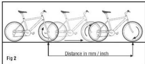
- Perform roll-out test (most accurate): See Figure 2.
text_image
Fig 2 Distance in mm / inchSTEP 1: Stand your bicycle upright. With your tires inflated to the proper pressure, rotate your front wheel so that the valve is located at the bottom (6 o'clock position). Make a mark on the ground to indicate the valve location.
STEP 2: Roll the bicycle forward in a straight line for one complete wheel revolution, until the valve is again at the bottom (ideally, you should be on the bike). Make a mark on the ground to indicate the valve location.
STEP 3: Measure the distance between the marks in millimeters (1 inch = 25.4mm). This value is your wheel circumference.
PROGRAM THE COMPUTER
Before using your Delta Wireless, you must program wheel size (see "Determine Wheel Size," above), select a speed scale (miles or kilometers), set the odometer (if desired), and set the clock. The first step is to set the clock. To enter the set-up mode, depress the SET button on the underside of the computer. See Figure 7.
SET THE CLOCK
The Delta Wireless is equipped with a digital clock that displays time of day in a 12 hour or 24 hour format.
STEP 1: Using the tip of a pen, depress the SET button on the underside of the computer to enter the Clock setup screen.
STEP 2: "12" or "24" will flash in the lower line of the display. Press the RIGHT button to select 12 hour or 24 hour mode. Press the LEFT button to confirm your selection and advance to the hours setting.
STEP 3: The hours will flash. Press the RIGHT button (or press and hold) to advance the hours. If you selected 12 hour mode, "PM" will appear for hours between noon and midnight. Press the LEFT button to advance to the minutes setting.
STEP 4: The minutes will flash. Press the RIGHT button (or press and hold) to advance the minutes. Press the LEFT button to set the time and advance to the speed scale selection screen.
SELECT SPEED SCALE
The Delta Wireless is capable of displaying speed and distance information in either miles or kilometers.
STEP 1: After setting the clock, the computer will automatically advance to the speed scale selection screen. "M/H" or "K/H" will flash in the display screen. Press the RIGHT button to select miles (M/H) or kilometers (K/H).
STEP 2: Press the LEFT button to confirm your selection and advance to the wheel size setting screen.
PROGRAM WHEEL SIZE
STEP 1: After the speed scale has been selected, the computer will automatically advance to the first wheel size programming screen (b1). The left-most digit will flash. Press the RIGHT button to adjust the flashing digit according to the wheel circumference value determined above. Press the LEFT button to advance to the next flashing digit.
STEP 2: Repeat this sequence until the correct wheel size has been entered. Then press the LEFT button to advance to the second wheel size setting screen (b2).
STEP 3: The left-most digit will flash. Press the RIGHT button to adjust the flashing digit. Press the LEFT button to advance to the next flashing digit.
STEP 4: Repeat this sequence until the second wheel size has been entered. Then press the LEFT button to advance to the odometer programming screen for the first wheel size.
PROGRAM THE ODOMETER
STEP 1: After programming both wheel sizes, the computer will automatically advance to the odometer setting screen for the first wheel size. (If you don't wish to program the odometer, press the SET button on the underside of the computer to exit the set-up mode.) The left-most digit will flash. Press the RIGHT button to adjust the value. Press the LEFT button to advance to the next flashing digit.
STEP 2: Repeat this sequence until the odometer value for the first wheel size has been set. Then press the LEFT button to advance to the odometer programming screen for the second wheel size.
STEP 3: Program the odometer value for the second wheel size as described above. Once the odometer value has been set correctly, press the SET button on the underside of the computer to exit the set-up mode and return to the main display screen.
INSTALLATION
Since your Ascent computer is wireless, installation is simple. Begin by attaching the handlebar bracket.
HANDLEBAR BRACKET INSTALLATION
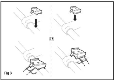
The handlebar bracket can be configured for stem or handlebar mounting. To change the configuration, remove the assembly screw, rotate the bracket base 90° and retighten the screw. Use the included zip-ties to attach the bracket in the desired location as shown in Figure 3. Once the bracket is securely installed, trim the excess zip-tie ends with scissors or fingernail clippers.
text_image
OR Fig 3COMPUTER HEAD INSTALLATION
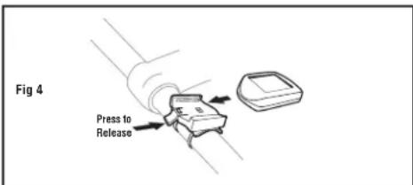
Slide the computer head onto the bracket from back to front until you hear a 'CLICK', indicating that the unit is locked in the bracket. See Figure 4. To remove the computer head, press the release tab at the front of the bracket and slide the computer head out of the bracket.
text_image
Fig 4 Press to ReleaseWHEEL MAGNET AND SENSOR INSTALLATION
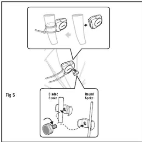
STEP 1: Using the included zip-ties, loosely mount the sensor (so that you can slide it around) to the fork blade so that it's on the same side of the bike as the handlebar bracket. The battery cover on the sensor/transmitter should face the wheel and should be attached to the front (leading) edge of the fork blade (to avoid problems should it ever come in contact with the spokes). See Figure 5. The Delta Wireless transmission range is 24" (60cm). The sensor/transmitter must be mounted within 24" of the receiver (computer head) in order for the signal to be received.
flowchart
graph TD
    A["Bladed Spoke"] --> B["Round Spoke"]
    B --> C["Step 1: Bladed to press"]
    C --> D["Step 2: Press to press"]
    D --> E["Step 3: Press to press"]
    E --> F["Step 4: Press to press"]
    F --> G["Step 5: Press to press"]
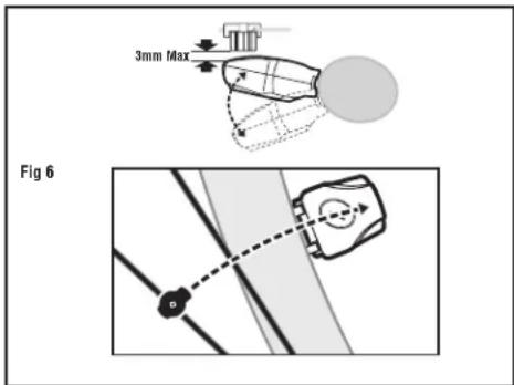
STEP 2: Attach the wheel magnet loosely to one of the spokes on the same side of the wheel as the sensor/transmitter. Adjust the position of the magnet and sensor by sliding both pieces up or down to achieve 1-3mm of clearance between the two (1mm is about the thickness of a penny). See Figure 6. If the magnet and sensor are not close enough, the computer will not pick up a reading or readings will be inconsistent and erratic. Most problems that occur when installing a new computer are related to magnet and sensor alignment and spacing.
text_image
3mm Max Fig 6STEP 3: Once the transmitter and wheel magnet are aligned properly, securely tighten both in place and trim the excess zip-tie ends with scissors or fingernail clippers.
TEST OF INSTALLATION
Once installation is complete, test the unit to make sure everything is adjusted and working properly. Pick up the front end of the bicycle and spin the front wheel. The computer should register a speed reading within 1-2 seconds. If not, check the alignment of the wheel magnet and sensor, and make sure that the space between the magnet and sensor is 3mm or less. Adjust as necessary and re-test.
NOTE: Wireless cyclocomputers are occasionally affected by electromagnetic interference. Common sources of electromagnetic signals include high voltage power lines, motor driven equipment and other wireless devices (such as heart rate monitors). If you experience unusually high speed readings, check your surroundings for possible sources of electromagnetic signals and move away from the source.
CHOOSE WHEEL SIZE
When switching your computer between bikes with different wheel sizes, don't forget to select the appropriate wheel size setting (1 or 2) for each bike. In the Trip Distance/Automatic Rider Timer display screen (DST/ATM), press and hold the RIGHT button for three seconds to change the wheel size.
RESET DISPLAY SCREENS
PARTIAL RESET
The Delta Wireless maintains a separate memory of Average Speed, Maximum Speed, Ride Time, Trip Distance and Odometer for each wheel size (1 and 2). The memory for each wheel size must be reset separately. During a partial reset, only data for the currently displayed wheel size will be cleared.
- To simultaneously reset Average Speed, Maximum Speed, Trip Distance and Ride Timer, press and hold the LEFT and RIGHT buttons for 4 seconds in any display screen.
- To reset only Average Speed and Maximum Speed, press and hold the RIGHT button for four seconds in the AVS/MAX display screen.
- To reset only Trip Distance, press and hold the RIGHT button for four seconds in the DST/ODO display screen.
- To reset only the Automatic Ride Timer, press and hold the RIGHT button for four seconds in the CLK/ATM display screen.
GLOBAL RESET
To reset ALL display screens for both wheel sizes and ALL programmed settings (including Clock, Odometer and wheel size settings), press the CLEAR button on the underside of the computer. See Figure 7.
NOTE: Please note that entering the set-up mode (by depressing the SET button on the underside of the computer) will not reset the display screens or clear any data. This means you can enter set-up mode to adjust wheel size settings, program the odometer or change the speed scale (miles/kilometers) without losing any data.
natural_image
Line drawing of hands using a tool to adjust or install a device (no text or symbols visible)MAINTENANCE
LOW BATTERY INDICATOR
When the computer battery is low, the low battery indicator will be displayed. Although this only indicates the state of the battery in the computer head, it's generally a good idea to replace both batteries (computer head and sensor/transmitter) at the same time (see "Battery Installation").