
IC-37A - Empfänger ICOM - Kostenlose Bedienungsanleitung
Finden Sie kostenlos die Bedienungsanleitung des Geräts IC-37A ICOM als PDF.


| Produkttyp | FM-Transceiver (220 MHz) |
| Marke | ICOM |
| Modell | IC-37A |
| Frequenzbereich | 220 – 225 MHz |
| Ausgangsleistung | HIGH: 25 W, LOW: 5 W |
| Empfangsempfindlichkeit | < 0,2 μV (12 dB SINAD) |
| Squelch-Empfindlichkeit | < 0,15 μV |
| Spannungsversorgung | 13,8 V DC ±15 %, 7 A max. |
| Stromaufnahme (Senden) | ca. 6,5 A (25 W), ca. 3,0 A (5 W) |
| Stromaufnahme (Empfang) | ca. 0,7 A (max. Audio), ca. 0,5 A (stummgeschaltet) |
| Abmessungen (B×H×T) | 140 × 38 (41) × 177 (191) mm |
| Gewicht | ca. 1,2 kg |
| Anzahl Speicherkanäle | 9 |
| Subaudible-Töne | 32 programmierbare Töne |
| Modulationsart | F3E (NFM) |
| Antennenimpedanz | 50 Ω, unbalanced |
| Zwischenfrequenzen | 1. ZF: 21,800 MHz, 2. ZF: 455 kHz |
| Audio-Ausgangsleistung | > 2 W an 4–8 Ω |
| Betriebstemperatur | -10 °C bis +60 °C |
| Besondere Funktionen | Dual-VFO, Speicherscan, programmierter Scan, Vollbereichsscan, Prioritätsfunktion, optionaler Sprachsynthesizer |
Häufig gestellte Fragen - IC-37A ICOM
Benutzerfragen zu IC-37A ICOM
0 Frage zu diesem Gerät. Beantworten Sie die, die Sie kennen, oder stellen Sie Ihre eigene.
Eine neue Frage zu diesem Gerät stellen
Laden Sie die Anleitung für Ihr Empfänger kostenlos im PDF-Format! Finden Sie Ihr Handbuch IC-37A - ICOM und nehmen Sie Ihr elektronisches Gerät wieder in die Hand. Auf dieser Seite sind alle Dokumente veröffentlicht, die für die Verwendung Ihres Geräts notwendig sind. IC-37A von der Marke ICOM.
BEDIENUNGSANLEITUNG IC-37A ICOM
INSTRUCTION MANUAL
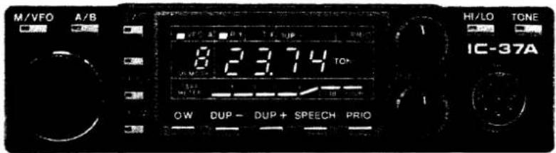
TABLE OF CONTENTS
I. SPECIFICATIONS 1
II. DESCRIPTION.... 2
III. INSTALLATION 3
IV. CONTROL FUNCTIONS.... 6
V. OPERATION 11
VI. INSIDE VIEWS 23
VII. TROUBLESHOOTING.... 25
VIII. BLOCK DIAGRAM 27
IX. SCHEMATIC DIAGRAM....SEPARATE
SECTION I SPECIFICATIONS
GENERAL
| Numbers of semiconductors | : Transistor 50FET 7IC 24Diode 97 |
| Frequency coverage | : 220MHz ~ 225MHz |
| Frequency resolution | : 5KHz/10KHz steps |
| Frequency control | : Microcomputer based 5KHz step Digital PLL synthesizer Independent Dual VFO Capability. |
| Frequency stability | : Within ±0.001% |
| Memory channels | : 9 channels with any inband frequency programmable |
| Usable conditions | : Temperature: -10°C ~ 60°C (14°F ~ 140°F)Operational time: Continuous |
| Antenna impedance | : 50 ohms unbalanced |
| Power supply requirement | : 13.8V DC ±15% (negative ground)7A Max. |
| Current drain (at 13.8V DC) | : Transmitting; High (25W) Approx. 6.5ALow (5W) Approx. 3.0AReceiving; At max audio output Approx. 0.7ASquelched Approx. 0.5A |
| Dimensions | : 38(41)mm(H) × 140mm(W) × 177(191)mm (D)( ): Shows the dimensions including projections |
| Weight | : Approx. 1.2kg |
TRANSMITTER
| Output power | : HIGH 25W LOW 5W |
| Emission mode | : 16F_3 (F3E 16K0) |
| Modulation system | : Variable reactance frequency modulation |
| Max. frequency deviation | : ±5KHz |
| Spurious emission | : More than 60dB below carrier |
| Microphone | : 600 ohm electret condenser microphone with push-to-talk and frequency UP/DOWN switches, and 16 key dual tone pad. |
| Operating mode | : Simplex, Duplex (Any offset in-band in 100KHz increments programmable) |
RECEIVER
| Receiving system | : Double-conversion superheterodyne |
| Modulation acceptance | : 16F_3 (F3E 16K0) |
| Intermediate frequencies | : 1st: 21.800MHz |
| 2nd: 455KHz | |
| Sensitivity | : Less than 0.2μV for 12dB SINAD |
| Less than 0.4μV for 20dB Noise quieting | |
| Squelch sensitivity | : Less than 0.15μV |
| Spurious response rejection ratio | : More than 60dB |
| Selectivity | : More than 15KHz at -6dB point |
| Less than 30KHz at -60dB point | |
| Audio output power | : More than 2.0W |
| Audio output impedance | : 4~8 ohms |
THE MOST COMPACT 220MHz MOBILE
The smallest 220MHz mobile available, the IC-37A measures only 38 millimeters high by 140 millimeters wide. As an added bonus, the IC-37A, through ICOM engineering, is able to contain an internal speaker to provide ease of mounting and make the unit one small compact complete package.
HIGH OUTPUT POWER
In such incredibly small package, the IC-37A is able to provide 25 watts of output power. And even though the IC-37A is the smallest available 220MHz mobile unit, it has sacrificed none of the features found in fully featured VHF mobiles.
9 MEMORIES
The IC-37A has nine memories available to store receive frequency, transmit offset, offset direction, and subaudible tone.
Memories are backed up by a lithium backup battery, which will store memories for up to seven years.
32 SUBAUDIBLE TONE ENCODER
The IC-37A comes complete with 32 standard subaudible tone encoder ready to go and controlled from the front panel knob. Each subaudible tone may be selected by the main tuning knob and stored into memory for easy access along with the frequency.
MULTI-PURPOSE SCANNING
The Memory Scan allows you to monitor nine different memory channels, the Programmed Scan provides scanning between two programmed frequencies, and Full range Scan scans the entire band. The scanning speed is switchable, and the auto-stop terminates scanning when a signal is received or a channel is free.
PRIORITY SCANNING
Priority may be selected to be either a memory channel or a VFO channel. By using sampling techniques, the operator can determine if a frequency he is interested in using is free or busy.
SPEECH SYNTHESIZER
As an added plus, the IC-37A features an optional speech synthesizer to verbally announce the receiver frequency of the transceiver through the simple push of a button. This allows the operator to hear what frequency he is operating on without looking at the frequency display.
SECTION III INSTALLATION
UNPACKING
Carefully remove your transceiver from the packing carton and examine it for signs of shipping damage. Should any be apparent, notify the delivering carrier or dealer immediately, stating the full extent of the damage. It is recommended you keep the shipping cartons. In the event storage, moving, or reshipment becomes necessary, they come in handy. Accessory hardware, cables, etc., are packed with the transceiver. Make sure you have not overlooked anything.
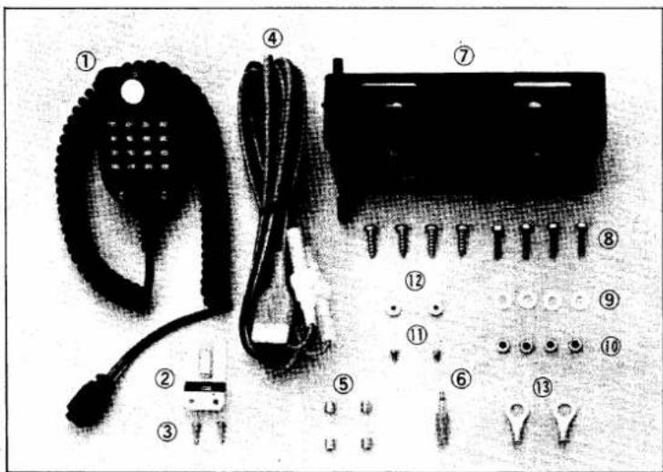
- Microphone (electret type) ..... 1
- Microphone hook 1
- Microphone hook retaining screws ... 2
- Power cord.... 1
- Spare fuses.... 2
- Plug for speaker 1
-
Mobile Mounting Bracket ..... 1
-
Mounting screws 8
- Flat washers.... 4
- Mounting screw's nuts 4
- Screws for additional bracket.....2
- Nuts for additional bracket ..... 2
- Battery terminal lugs ..... 2
LOCATION
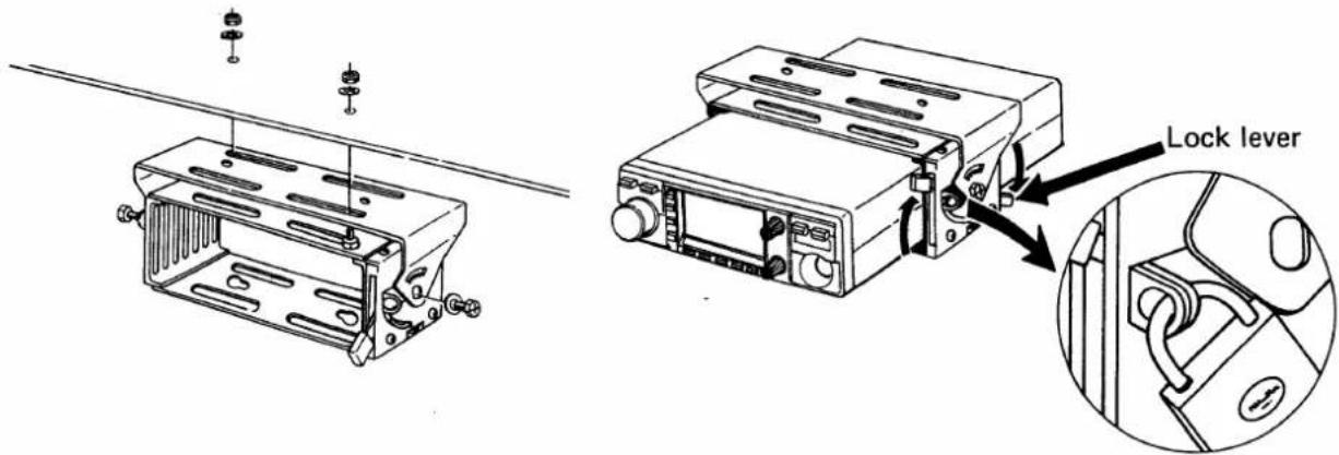
Where you place the transceiver in your automobile is not critical and should be governed by convenience and accessibility. Since the unit is so compact, many mobile possibilities present themselves. In general, the mobile mounting bracket will provide you with some guide as to placement. Any place where it can be mounted with metal screws, bolts, or pop-rivets will work. For fixed station use, a power supply should be designed to produce 7 amps for the transceiver.
Mounting bracket installation
POWER REQUIREMENTS
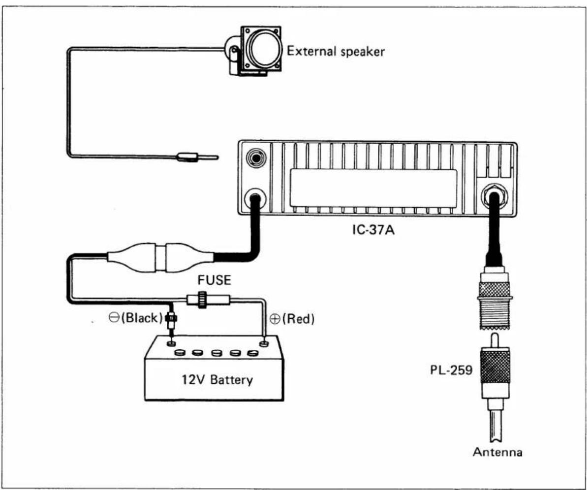
The transceiver is supplied ready to operate from any regulated 13.8V DC, 7 ampere negative ground source. An automobile 12 voit, negative ground, system is usually more than adequate. Some note must be taken, however, of the condition of the vehicle's electrical system. Items such as low battery, worn generator/alternator, poor voltage regulator, etc., will impair operation of your transceiver as well as the vehicle. High noise generation or low voltage delivery can be traced to these deficiencies. If an AC power supply is used with your transceiver, make certain it is adequately regulated for both voltage and current. Low voltage while under load will not produce satisfactory results from your transceiver. Receiver gain and transmitter output will be greatly impaired. Caution against catastrophic failure of the power supply should be observed.

Included with your transceiver is a DC power cable with plug attached. The Red Wire is positive (+), the Black, negative (−). If your mobile installation permits, it is best to connect these directly to the battery terminals. This arrangement eliminates random noise and transient spikes sometimes found springing from automotive accessory wiring. If such an arrangement is not possible, then any convenient B+ lead in the interior of the vehicle and the negative frame can be utilized. Remember, the unit operates on a negative ground system only; it cannot be used in a positive ground automobile. After making your connections, simply insert the plug into your transceiver.
ANTENNA
The most important single item that will influence the performance of any communication system is the antenna. For that reason, a good, high-quality, gain antenna of 50 ohms impedance is recommended, fixed or mobile. In VHF as well as the low bands, every watt of ERP makes some difference. Therefore, 25 watts average output plus 3dB of gain antenna equals 50 watts ERP, presuming low VSWR of course. The few extra dollars invested in a gain type antenna is well worth it. When adjusting your antenna, whether mobile or fixed, by all means follow the manufacturer's instructions. There are some pitfalls to be aware of. For example, do not attempt to adjust an antenna for lowest VSWR when using a diode VSWR meter not engineered for VHF applications. Such readings will invariably have an error of 40% or more. Instead, use an in line watt meter similar to the Bird Model 43 or Sierra Model 164B with VHF cartridge. Further, when adjusting a mobile antenna, do so with the motor running preferably above normal idling speed. This will insure proper voltage level to the transceiver.
The RF coaxial connector on the rear panel mates with a standard PL-259 connector. Some models may have metric threads. In any event, the RF connector will mate with almost any PL-259 connector if care is taken to seat them properly.
MICROPHONE
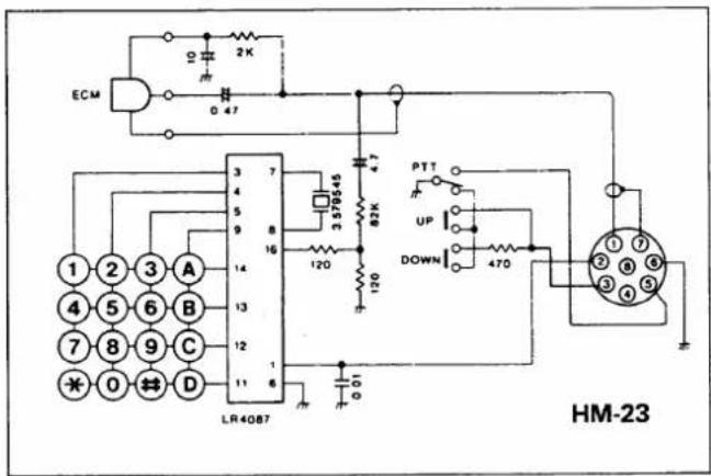
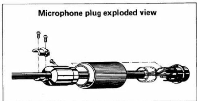
A high quality electret condenser microphone is supplied with your transceiver. Merely plug it into the proper receptacle on the front panel. Should you wish to use a different microphone, make certain it has a proper output level. Particular care should be exercised in wiring also, as the internal electric switching system is dependent upon it. See the schematic for the proper hookup.
EXTERNAL SPEAKER
An external speaker plug is supplied with your unit in the event another speaker is desirable. The external speaker impedance should be 4 \~ 8 ohms, and when used, will disable the internal speaker. A 4 \~ 16 ohm headset can be utilized as well.
FRONT PANEL
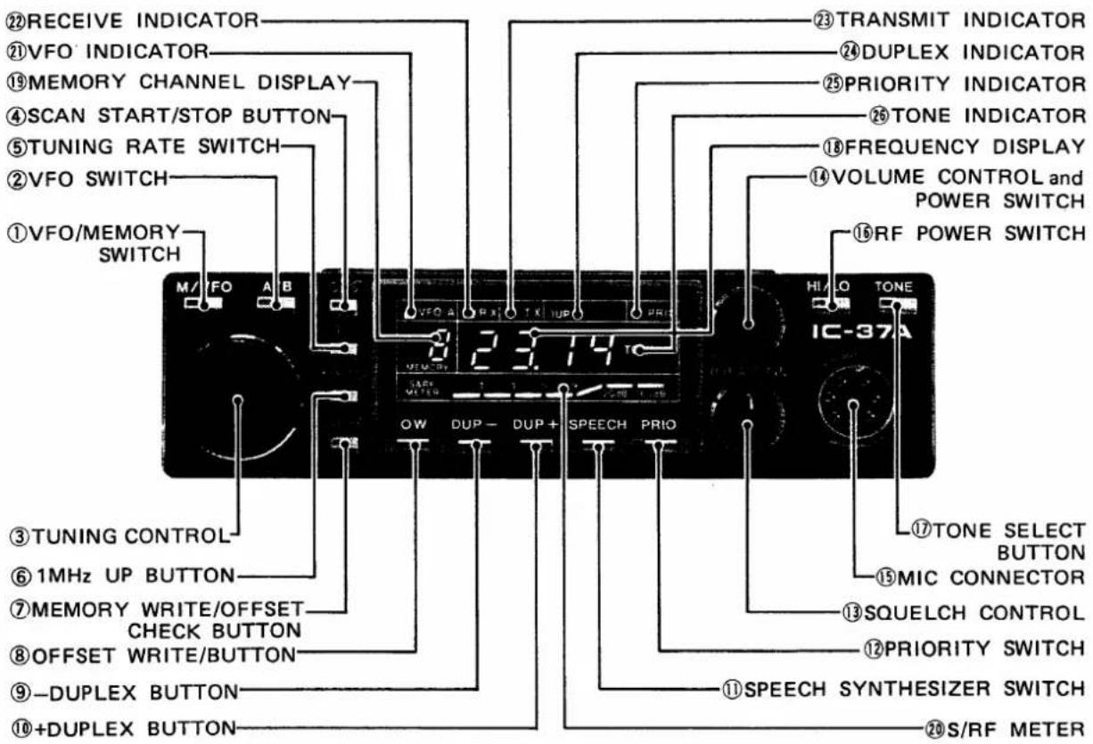
1: VFO/MEMORY SWITCH
Each push switches from MEMORY CHANNEL operation to VFO operation alternately. When the set is in the MEMORY CHANNEL operation, the letter "M" is displayed at the MEMORY CHANNEL DISPLAY. The selected memory channel number is also displayed at the MEMORY CHANNEL DISPLAY, however this number remains even if the VFO operation is selected.
2. VFO SWITCH
Selects either VFO, "A" or "B", for tuning. When the switch is in the out position, VFO A is selected and the VFO INDICATOR is illuminated. When the switch is pushed in, VFO B is selected and the VFO INDICATOR goes off.
3. TUNING CONTROL
In the VFO operation mode, rotating the TUNING CONTROL clockwise increases the frequency, while rotating it counterclockwise decreases the frequency. The frequency is changed in 5KHz steps when the TUNING RATE switch is pushed in and in 10KHz steps when the TUNING RATE switch is in the out position.
When tuning up past the upper limit of the operation band, the frequency will automatically revert to the lower limit. Likewise, when tuning down past the lower limit, the frequency will automatically revert to the upper limit.
4. SCAN START/STOP BUTTON
Starts and stops any of the scan functions. When depressing it to restart the scan, it will start from the memory channel or frequency displayed.
5. TUNING RATE SWITCH
Selects the tuning frequency steps. When this switch is pushed in, the frequency changes in 5KHz steps by turning the TUNING CONTROL. When the switch is in the out position, the frequency changes in 10KHz steps.
6. 1MHz UP BUTTON
Each push increases the frequency in 1MHz steps. The lower digits will not change.
7. MEMORY WRITE/OFFSET CHECK BUTTON
In the SIMPLEX mode (neither DUP— nor DUP+ is illuminated), by pushing this button, the displayed VFO frequency is written into the selected memory channel (the memory channel number is displayed on the MEMORY CHANNEL DISPLAY). Each memory channel stores not only an operating frequency but also an offset frequency, offset direction and subaudible tone frequency (tone number).
In the DUPLEX mode, while holding this button, the receive frequency changes to the offset transmit frequency. Thus the repeater input frequency may be checked.
8. OFFSET WRITE BUTTON
While holding this button, the offset frequency is displayed on the FREQUENCY DISPLAY. This offset frequency can be changed by pushing the -DUPLEX BUTTON, +DUPLEX BUTTON or 1MHz UP BUTTON. Each push of the -DUPLEX button, decreases the offset frequency 100KHz, the +DUPLEX button increases 100KHz and the 1MHz UP button increases 1MHz.
9. -DUPLEX BUTTON
By pushing this button, the set is in the duplex mode and the transmit frequency will be set 1.6MHz (This can be changed to any 100KHz steps in-band frequency.) below the receive frequency. To turn off the duplex, push this button again.
10. +DUPLEX BUTTON
By pushing this button, the set is in the duplex mode and the transmit frequency will be set 1.6MHz (This can be changed to any 100KHz steps in-band frequency.) above the receive frequency. To turn off the duplex, push this button again.
11. SPEECH SYNTHESIZER SWITCH
Each push turns on the optional speech synthesizer which verbally announces the displayed frequency in English.
12. PRIORITY SWITCH
Turns the priority function ON and OFF.
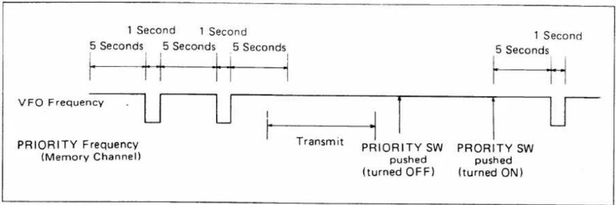
During a QSO or if receiving on a frequency with a VFO, if you would like to monitor your favorite frequency or a calling frequency, set the memory channel number to containing that frequency, and push the priority button. The receiving frequency will go to the channel for a moment every five seconds.
When receiving on a frequency with a memory channel, by pushing the priority button, the receiving frequency will go to the VFO frequency previously set for a moment every five seconds.
13. SQUELCH CONTROL
Turning this control clockwise sets the squelch threshold higher. To turn OFF the squelch function, turn this control completely counterclockwise.
14. VOLUME CONTROL and POWER SWITCH
When the control is turned completely counterclockwise, the power is OFF. By turning the control clockwise beyond the "click", the unit is turned ON and the audio level increases by further rotating it clockwise.
15. MIC CONNECTOR
Connect the supplied microphone to this jack. If you wish to use a different microphone, refer to the drawings on page 5.
16. RF POWER SWITCH
Selects the RF output power HIGH or LOW. When the switch is out position, the output power is HIGH, 25 watts. When the switch is pushed in, the output power is LOW, 5 watts.
17. TONE SELECT BUTTON
While holding this button, the subaudible tone number is displayed on the FREQUENCY DISPLAY and the TONE INDICATOR is illuminated, and by turning the TUNING CONTROL, the tone number can be changed.
18. FREQUENCY DISPLAY
The four large-7 segment LED's represent the digits between 10MHz and 10KHz and small "50" for 5KHz of the operating frequency. The frequency indicated is the carrier frequency.
19. MEMORY CHANNEL DISPLAY
Shows that the set is in the MEMORY CHANNEL MODE or not, and the selected memory channel number. When the set is in the MEMORY CHANNEL MODE, the letter "M" is displayed here.
20. S/RF INDICATOR
Indicates S-unit and RF output level with seven LED's in line. The numbers on the S-meter represent S1 through S9 and 60dB over S9. The RF output level meter functions only as a relative output meter and does not indicate the wattage. These functions are switched automatically when T/R switching is made.
21. VFO INDICATOR
When the VFO A is selected, this indicator illuminates.
22. RECEIVE INDICATOR
Illuminates when the squelch is opened in the receive mode.
23. TRANSMIT INDICATOR
Illuminates in the transmit mode.
24. DUPLEX INDICATOR
Illuminates when the set is in the DUPLEX mode. "DUP—" shows the transmit frequency will be below the receive frequency, and "DUP+" shows the transmit frequency will be above the receive frequency.
25. TONE INDICATOR
Illuminates when the subaudible tone encoder is activated. When the selected tone number is "00", the tone encoder is turned off and this indicator does not illuminate.
REAR PANEL
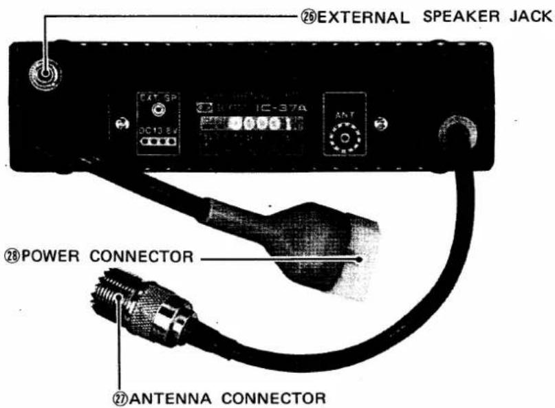
26. EXTERNAL SPEAKER JACK
When an external speaker is used, connect it to this jack. Use a speaker with an impedance of 4 \~ 8 ohms. When the external speaker is connected the built-in speaker does not function.
27. ANTENNA CONNECTOR
This is used to connect an antenna to the set. Its impedance is 50 ohms and connects with a PL-259 connector.
28. POWER CONNECTOR
Connect the supplied power cord to this connector.
UNDER THE ACCESS COVER
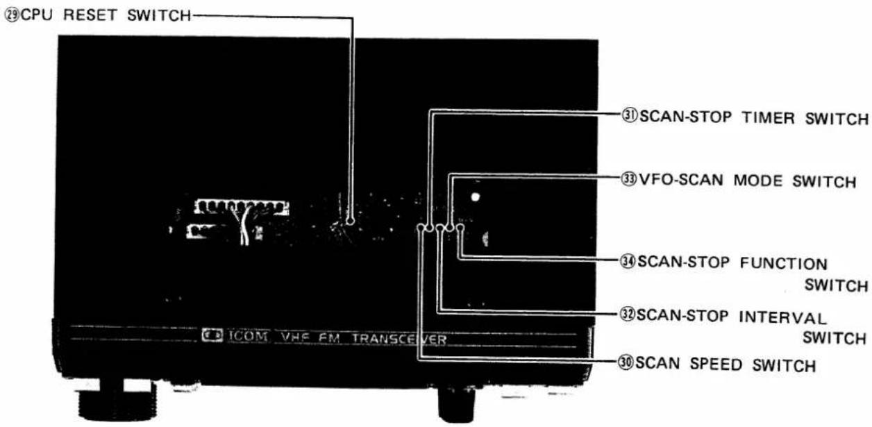
29. CPU RESET SWITCH
Resets the CPU into the initial condition. If the CPU seems abnormal, push this switch while the power is ON, and the CPU will be reset.
30. SCAN SPEED SWITCH
Switches the scanning speed in any scan mode. Place the switch to the desired speed; "FAST" or "SLOW".
31. SCAN-STOP TIMER SWITCH
Switches the scan-stop interval function ON and OFF.
32. SCAN-STOP INTERVAL SWITCH
Switches the interval of the scan auto-stopping time. Place the switch to the desired interval; "LONG" for about 9 seconds or "SHORT" for about 3 seconds.
33. VFO-SCAN MODE SWITCH
Switches the VFO-scan function to either the programmed scan (PS) or the full range scan (FS).
34. SCAN-STOP FUNCTION SWITCH
Switches the scan-stop function to either stop on a busy channel or stop on an empty channel.
HOW TO TUNE
The following instructions are for the tuning. Please read carefully and understand fully before turning ON your unit. Proper tuning is necessary for optimum operation.
PRESET FREQUENCY
When the POWER switch is first turned on or the CPU RESET switch is pushed, the FREQUENCY DISPLAY will be "20.00" representing 220.000MHz, and the MEMORY CHANNEL DISPLAY will be "0" representing memory channel 0. After this the frequency as well as the memory channel number, duplex mode, duplex offset, etc. will remain as it had previously, even if the power switch has been turned off.
TUNING CONTROL
When the set is in the VFO operation mode (the letter "M" is not illuminated in the MEMORY CHANNEL DISPLAY), rotating the TUNING CONTROL clockwise increases the frequency; turning it counterclockwise decreases the frequency in 5KHz steps when the TUNING RATE switch is pushed in, or in 10KHz steps when the TUNING RATE switch is in the out position.
When you reach to the highest edge, turning the TUNING CONTROL clockwise will bring the operating frequency to the lowest edge, and you can continue increasing the frequency from there by continuing to rotate the knob clockwise. The VFO endless system functions in the same way when decreasing the frequency from the lowest edge, and will prevent you from inadvertently operation out of the amateur radio band.
VFO/MEMORY SWITCH and VFO SWITCH
By pushing the VFO/MEMORY switch, the set is switched in the VFO operation mode and the MEMORY CHANNEL operation mode alternately.
The CPU in the IC-37A contains two VFO's for both receiving and transmitting. The VFO's are labeled "VFO A" and "VFO B", and are selectable with the VFO switch. The dual VFO system gives the IC-37A many very convenient features. Please read this section very carefully and perform the operation several times until you are comfortable with this system. Try the example for practice.
-
VFO A is for both transmitting and receiving and is selected by placing the VFO switch in the out position. The transmit and receive frequency will be controlled by VFO A, and stored in "A" memory.
-
VFO B is for both transmitting and receiving and is selected by placing the VFO switch in the pushed in position. The transmit and receive frequency will be controlled by VFO B, and stored in "B" memory.
NOTE: The memory channel operation is described in the "MEMORY CHANNEL OPERATION" on page 14.
■ Switching from one VFO to the other VFO does not clear the first VFO. The frequency is retained in the VFO's memory.
FOR EXAMPLE:
If 224.740MHz is set with the VFO A, and the VFO switch is pushed to select the VFO B, the frequency readout will show the VFO B's frequency, but 224.740MHz is still stored in the VFO A's memory. Pushing the VFO switch again to return to the VFO A, "24.74" will be displayed on the readout. Accordingly, if the switch is pushed again, the frequency that was set with the VFO B will appear. This allows you to set a certain frequency with one VFO, work up and down the band with the other VFO, and periodically check the set frequency simply by switching between the VFO A and B. It also allows you to search for a clear frequency with one VFO, while keeping your operating frequency on the other VFO. When you have found a clear frequency, switch back to your operating frequency, inform the station you are in contact with of the new frequency, and switch back. It's that simple.
DUPLEX (REPEATER) OPERATION
The -DUPLEX button and +DUPLEX button allow DUPLEX (repeater) operation. The offset frequency is preset for the standard separation; 1.6MHz, but this frequency can be reset for any in-band 100KHz increments frequency.
- When both the -DUPLEX and +DUPLEX buttons have not been pushed and the DUPLEX INDICATOR is not illuminated, the set is in the SIMPLEX mode; the receive frequency and transmit frequency are controlled with the displayed frequency which is set by a VFO or MEMORY CHANNEL.
- When the -DUPLEX button is pushed, the set is in the DUPLEX mode and the transmit frequency is set 1.6MHz (or reset offset frequency) below the receive frequency. At the same time, the letters "DUP—" are illuminated above the frequency display. To turn off the DUPLEX mode, push the -DUPLEX button again.
- When the +DUPLEX button is pushed, the set is in the DUPLEX mode and the transmit frequency is set 1.6MHz (or reset offset frequency) above the receive frequency, and the letters "DUP+" are displayed. To turn off the DUPLEX mode, push the +DUPLEX button again.
- When the set is in the DUPLEX mode, while the MEMORY WRITE/OFFSET CHECK button is pushed, the receive frequency becomes the transmit frequency, so you can receive on a repeater's input frequency.
■ Pushing the +DUPLEX or -DUPLEX button will allow you to access a repeater that has a 1.6MHz input/output frequency separation.
FOR EXAMPLE:
Set the display-frequency to 224.820MHz. Then push the “-DUPLEX” button. The letters “DUP-” is illuminated, and “24.82” will be shown on the display during receive and “23.22” during transmit. You are now receiving on 224.820MHz and transmitting on 223.220MHz, so you can access a 223.220/224.820 repeater.
If you push the MEMORY WRITE/OFFSET CHECK button, "23.22" will be shown on the display and you can receive on 223.220MHz, i.e., repeater input frequency, while the button is pushed.
If you change the receive frequency from 224.820MHz to 224.780MHz, the transmit frequency will change from 223.220MHz to 223.180MHz, so now you can access a 223.180/224.780 repeater.
Pushing the "+DUPLEX" button changes the transmit frequency to 1.6MHz above the receive frequency.
If you set the receive frequency to 223.140MHz, the transmit frequency will be 224.740MHz.
This function will be available with any VFO or MEMORY CHANNEL.
RESETTING THE OFFSET FREQUENCY
The offset frequency can be reset to any 100KHz steps in-band frequency.
By pushing the OFFSET WRITE button, the FREQUENCY DISPLAY shows the 1MHz to 10KHz digits of the offset frequency instead of the operating frequency. If the offset frequency has not been changed since turning power ON, "1.60" will be shown on the frequency display.
While the OFFSET WRITE button is pushed, pushing the -DUPLEX button decreases the offset frequency; pushing the +DUPLEX button increases the frequency in 100KHz steps. Push the -DUPLEX or +DUPLEX button to obtain the desired offset frequency, then release the OFFSET WRITE button, and the desired offset frequency is written into the CPU and maintained until a new offset frequency is reset.
NOTE: The 1MHz UP button can also be used to reset the offset frequency. While pushing the OFFSET WRITE button, each push of the 1MHz UP button increases the offset frequency in 1MHz steps.
■ What to do if you want to operate a repeater that has a frequency separation other than ±1.6MHz. (For example; 1.0MHz)
FOR EXAMPLE:
Push the OFFSET WRITE button, and the FREQUENCY DISPLAY shows "1.60". While pushing the OFFSET WRITE button, push the -DUPLEX button six times to show "1.00" on the display, then release the OFFSET WRITE button.
Push the -DUPLEX button to show "DUP—" on the display and tune to 224.740MHz. "24.74" will be shown on the display during receive and "23.74" during transmit. You are now receiving on 224.740MHz and transmitting on 223.740MHz, so you can access a 223.740/224.740 repeater.
If you change the receiving frequency from 224.740MHz to 224.660MHz, the transmitting frequency will change from 223.740MHz to 223.660MHz, so now you can access a 223.660/224.660 repeater.
MEMORY CHANNEL OPERATION
MEMORY CHANNEL SELECTION
When the power switch is first turned ON or the CPU RESET button is pushed, the set initially operates in the VFO mode and memory channel number "0" is displayed. By pushing the VFO/MEMORY switch, the set is switched into the MEMORY CHANNEL MODE and a frequency which has been stored in the MEMORY CHANNEL 0 is displayed on the frequency display. In addition, the letter "M" is displayed next to the channel number on the MEMORY CHANNEL DISPLAY to indicate the set is in the MEMORY CHANNEL MODE.
FOR EXAMPLE:
When "223.550MHz" and "SIMPLEX" (neither -DUPLEX nor +DUPLEX) are memorized in the VFO A, and "223.340MHz" and "+DUPLEX" are memorized in the MEMORY CHANNEL 0. The set is in the VFO mode, the display shows "23.55" and memory channel number "0".
By pushing the VFO/MEMORY switch, the display will show "23.34", "DUP+", memory channel number "0" and the letter "M" next to the channel number.
By turning the TUNING CONTROL, memory channels can be selected. Turning clockwise increases the channel number and counterclockwise decreases the number, and respective frequency, and duplex mode and tone (if memorized), are displayed on the display.
When you select a memory channel that has never had any frequency stored, the frequency display does not show any frequency, but the MHz deciamal. However, the set will work with the frequency, duplex mode and tone (if memorized) of the memory channel or VFO which were previously displayed.
FOR EXAMPLE:
When "224.940MHz" and "-DUPLEX" are memorized in the memory channel 1, and no frequency is in the channel 2. By turning the TUNING CONTROL to select the channel 1, the display will show "24.94", letter "M", memory channel number "1" and letters "DUP-".
By turning the TUNING CONTROL clockwise further, the memory channel number will change to "2", but this channel has never had a frequency memorized, thus the frequency display will show the MHz decimal only. However, the set will work with the frequency and operation mode of the channel 1, i.e., "224.940MHz" and "-DUPLEX".
While turning the TUNING CONTROL, when memory channel limits are reached (i.e., "0" or "8"), the next memory channel entered will be the opposite limit (i.e., "8" or "0").
NOTE: The displayed frequency cannot be changed by turning the TUNING CONTROL in the MEMORY CHANNEL MODE. However, the 1MHz UP button functions and by pushing this button, the displayed frequency is changed 1MHz at a time. (100KHz and lower digits of the frequency will remain as it had in the previous one.) Each push increases the operating frequency 1MHz at a time from the previous one, and this frequency can be memorized into the selected memory channel by pushing the MEMORY WRITE button.
MEMORY-WRITE (PROGRAMMING THE MEMORY CHANNELS)
Any operating frequency, duplex mode, offset frequency and subaudible tone frequency can be memorized into a memory.
- Set the operating frequency to desired one using a VFO. For example, set it for "224.740 MHz" by using VFO B.
- Push the VFO/MEMORY switch to set in the MEMORY CHANNEL mode, then select a memory channel to be used by turning the TUNING CONTROL. For example, select it at memory channel 5.
- The contents of the channel are displayed on the display. If you don't want to rewrite the contents, select another memory channel which has erasable contents or no memorized frequency. (When no frequency has been memorized, only the MHz decimal is displayed at the frequency position.) After checking, push the VFO/MEMORY switch again to return to the VFO.
- One push of the MEMORY WRITE button erases the previously memorized contents (if any) and memorizes the displayed frequency into the selected memory channel (at this time channel 5).
- If you want to memorize a duplex mode and its offset frequency, and/or subaudible tone, push the VFO/MEMORY switch again to return the MEMORY CHANNEL. Then push the desired duplex mode button either "DUP—" or "DUP+", and the duplex mode and its offset frequency are memorized in the memory channel. In the like manner, while pushing the TONE SELECT button, turn the TUNING CONTROL to get desired tone number then release the TONE SELECT button, and the tone function is memorized in the memory channel.
- Memorize other desired frequencies and so on into other memory channels in the same manner. Memory channels 0 and 1 are used for the PROGRAMMED SCAN. For PROGRAMMED SCAN operation, refer to "SCAN OPERATION" on page 16.
TUNING BY UP/DOWN BUTTONS ON THE MICROPHONE
FREQUENCY CONTROL
With each push of the UP or DN (down) button on the microphone, the operating frequency is changed one increment up or down respectively. In the same way, by depressing the button continuously, the operating frequency is changed up or down the same as turning the TUNING CONTROL. The tuning rate is according to the setting of the TUNING RATE switch.
This function is effective in the VFO mode.
MEMORY CHANNEL SELECTION
In the MEMORY CHANNEL mode, with each push of the UP or DN (down) button on the microphone, the operating memory channel is changed in order. In the same way, while depressing the button continuously the operating MEMORY CHANNEL is changed up or down continuously in order.
SCANNING OPERATION
MEMORY SCAN
This is used to scan the nine memory channels continuously.
- Program nine desired frequencies into MEMORY CHANNELS 0 \~ 8.
- Push the VFO/MEMORY switch to select the MEMORY CHANNEL mode.
- Push the SCAN START/STOP (S/S) button, and the operating frequency starts scanning the programmed frequencies in the MEMORY CHANNELS from the displayed channel to the higher memory channels in order.
- When the scanning reaches the highest memory channel (memory channel 8), it automatically returns to the lowest channel (memory channel 0) and continues scanning up to provide endless scanning operation.
- If the SQUELCH is engaged, the scan stops when the squelch is opened and a signal is received. To stop scanning without opening the squelch, push the S/S button. Push it again to restart the scanning.
This function can be changed to stop when the squelch is closed, i.e., an empty channel, by setting the SCAN-STOP FUNCTION SWITCH located under the access cover to the EMPTY position. (At this time, start the scan when a signal is received and the squelch is opened.) - The SCAN SPEED can be changed by the SCAN SPEED SWITCH under access cover. Place the switch to desired speed, FAST or SLOW.
PROGRAMMED SCAN
This is used to scan between two desired frequencies, which are programmed in MEMORY CHANNELS 0 and 1, by setting the VFO-SCAN MODE SWITCH located under the access cover to the "PS" position.
- Program the frequencies of the high and low edges of the desired scanning range into the memory channels 0 and 1. Regardless of which channel the higher frequency is programmed in, the scan starts from the high edge of the range.
For example, 224.200MHz is in the memory channel 0 and 224.700MHz in the channel 1.
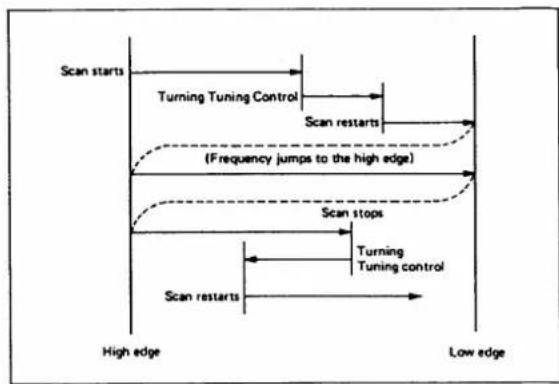
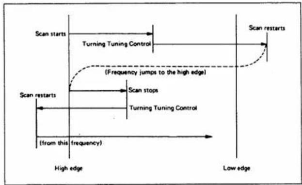
- If the set is in the MEMORY CHANNEL mode, push the VFO/MEMORY switch to set in the VFO mode. Pushing the SCAN START/STOP button starts the scan from the VFO frequency or the high edge (224.700MHz) to the low edge.
If the VFO frequency is below the low edge frequency, the frequency jumps to the high edge (224.700MHz) and the scan starts from the VFO frequency and scans down to the low edge, but it will return to the programmed high edge frequency.
The scanning frequency increments depend on the TUNING RATE SWITCH setting.
-
When the scanning frequency reaches the low edge (224.200MHz), it automatically returns to the high edge and continues scanning down to provide endless scanning operation.
-
While the SQUELCH is engaged, the squelch opening as a signal is received will stop the scanning automatically on the frequency. If the RECEIVE indicator is lit because the SQUELCH is not engaged, the scan does not start.
- To stop the scan operation, push the SCAN START/STOP (S/S) button. Pushing the S/S button again restarts the scan from the frequency at which it stopped.
- When the scanning has automatically stopped on a frequency, the frequency can not be changed by turning the TUNING CONTROL. If you wish to change the frequency, first, push the SCAN START/STOP button to clear the scan function.
flowchart
graph TD
    A["Scan starts"] --> B["Turning Tuning Control"]
    B --> C["Scan restarts"]
    C --> D["(Frequency jumps to the high edge)"]
    D --> E["Scan stops"]
    E --> F["Turning Tuning control"]
    F --> G["Scan restarts"]
    G --> H["High edge"]
    G --> I["Low edge"]
flowchart
graph TD
    A["Scan starts"] --> B["Turning Tuning Control"]
    B --> C["(Frequency jumps to the high edge)"]
    C --> D["Scan stops"]
    D --> E["(from this frequency)"]
    E --> F["High edge"]
    F --> G["Low edge"]
    G --> H["Scan restarts"]
VFO FULL RANGE SCAN
This is to scan the entire band between 220MHz and 225MHz.
- Push VFO/MEMORY Switch to select the VFO mode, and the VFO-SCAN FUNCTION Switch to "FS" position. Depressing the S/S button starts the scan from the VFO frequency to the low edge. The scanning frequency increments depend on the TUNING RATE Switch setting.
- When the scanning frequency reaches the low edge, it automatically returns to the high edge and continues scanning down to provide endless scanning operation.
- Other operations are the same as the PROGRAMMED SCAN and MEMORY SCAN.
The scanning speed can be selected by the SCAN SPEED Switch located under the access cover. Setting the switch in the FAST position makes the scanning speed faster.
While the SCAN is operating even if the SCAN stops on a frequency, the decimal point between the 10MHz and 1MHz digits of the frequency display is illuminated.
RESUMING SCAN
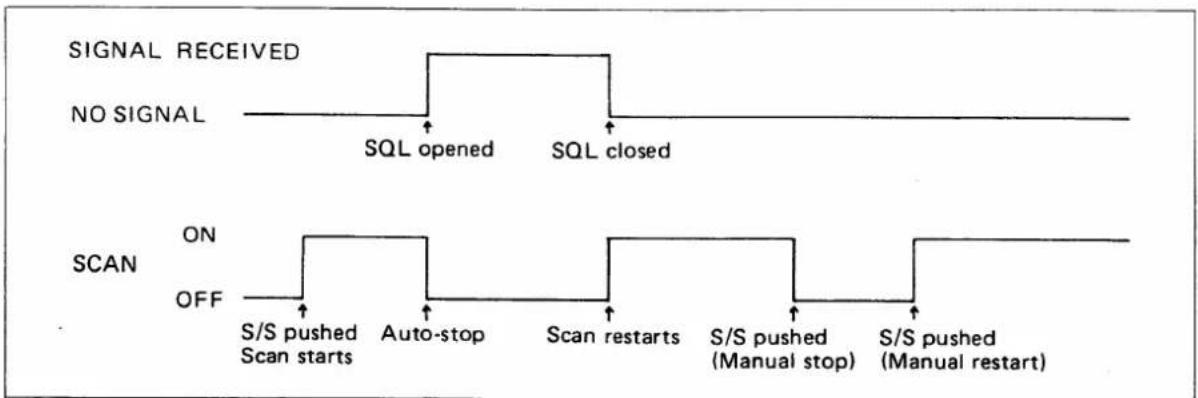
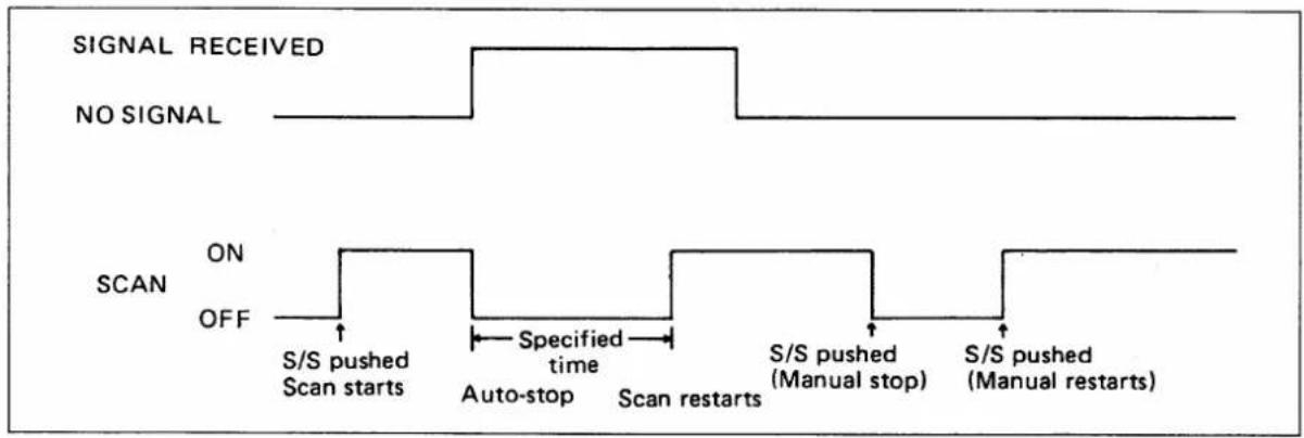
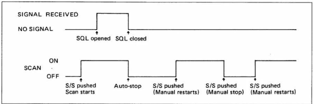
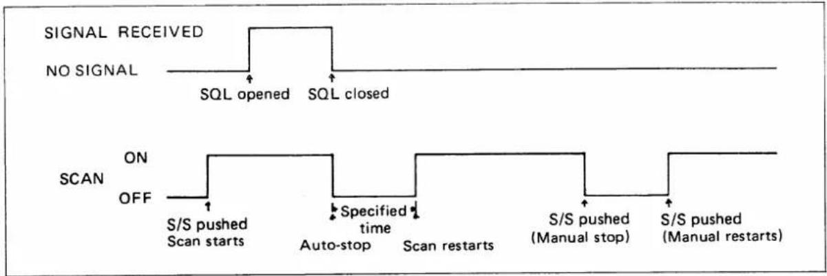
All scan modes are provided with the resume scan function. When the scan has been stopped by the auto-stop function, the scan will restart after the cause goes away, or after passing a specified time.
- By setting the SCAN-STOP TIMER Switch in OFF position and the SCAN-STOP FUNCTION SWITCH in BUSY position (both located under the access cover), the scan will stop on a signal (by opening the squelch), then the scan will restart with loss of the signal.
flowchart
graph TD
    A["SIGNAL RECEIVED"] --> B["NO SIGNAL"]
    B --> C["SQL opened"]
    B --> D["SQL closed"]
    E["SCAN ON"] --> F["OFF S/S pushed Scan starts"]
    E --> G["Auto-stop Scan starts"]
    E --> H["Scan restarts Scan restarts"]
    E --> I["S/S pushed (Manual stop)"]
    E --> J["S/S pushed (Manual restart)"]
- By setting the SCAN-STOP TIMER Switch in ON position and the SCAN-STOP FUNCTION SWITCH in BUSY position, the scan will stop on a signal, and will restart after specified time is passed, whether a signal has been received or not. The scan stop time is selectable 3 seconds (SHORT) and 9 seconds (LONG) with the SCAN-STOP INTERVAL Switch located under the access cover.
- By setting the SCAN-STOP FUNCTION SWITCH in EMPTY position and the SCAN-STOP TIMER Switch in OFF position, the scan will stop on an empty channel (by closing the squelch), then the scan will restart when a signal is received.
flowchart
graph TD
    A["SIGNAL RECEIVED"] --> B["SQL opened"]
    B --> C["SQL closed"]
    D["NO SIGNAL"] --> E["SCAN ON OFF"]
    E --> F["S/S pushed Scan starts"]
    E --> G["Auto-stop"]
    E --> H["S/S pushed (Manual restarts)"]
    E --> I["S/S pushed (Manual stop)"]
    E --> J["S/S pushed (Manual restarts)"]
- By setting the SCAN-STOP FUNCTION SWITCH in EMPTY position and the SCAN-STOP TIMER Switch in ON position, the scan will stop on an empty channel, then will restart after specified time is passed, whether a signal has been received or not.
flowchart
graph TD
    A["SIGNAL RECEIVED"] --> B["NO SIGNAL"]
    B --> C["SQL opened"]
    B --> D["SQL closed"]
    E["SCAN ON"] --> F["OFF S/S pushed Scan starts"]
    G["SCAN OFF"] --> H["Specified time Auto-stop"]
    I["SCAN ON"] --> J["Auto-stop Scan restarts"]
    K["SCAN ON"] --> L["Manual stop S/S pushed (Manual stops)"]
    M["SCAN ON"] --> N["Manual restart S/S pushed (Manual restarts)"]
Set the SCAN-STOP TIMER Switch, SCAN-STOP INTERVAL Switch, and SCAN-STOP FUNCTION SWITCH as to your own choice.
PRIORITY FUNCTION
This function provides a way to check your favorite channel, such as a local repeater or a calling channel, that is written into a memory channel while operating on a VFO frequency.
The following steps are taken to utilize the PRIORITY FUNCTION.
- Write your favorite frequency into a memory channel.
- Push the VFO/MEMORY switch to select the MEMORY CHANNEL mode, and turn the TUNING CONTROL to select the desired memory channel. Push the VFO/MEMORY switch to return in the VFO mode.
- By pushing the PRIORITY button, the PRIORITY INDICATOR is lit and the set receives on a VFO frequency, a period of five seconds and on the priority channel (selected memory channel) one second, and repeats this function until the PRIORITY button is pushed again.
- If the set is turned to the transmit mode while the priority function, priority is disabled, and the transmit frequency will be the VFO frequency in SIMPLEX mode, or its OFFSET frequency in DUPLEX mode. When returning to receive mode, the priority function will be resumed.
- If you wish to stop the priority function, push the PRIORITY button again, and the PRIORITY INDICATOR is turned off and the operating frequency goes to the VFO frequency.
- If you wish to continue the operation on the PRIORITY CHANNEL (MEMORY CHANNEL), push the VFO/MEMORY switch to select the MEMORY CHANNEL mode.
- While the set is in the MEMORY CHANNEL mode, by pushing the PRIORITY button, the set receives on the selected MEMORY CHANNEL frequency, a period of five seconds and on the VFO frequency one second. Reversing the relationship of the VFO and MEMORY CHANNEL as described above.
TONE ENCODER OPERATION
The IC-37A is equipped with a subaudible tone encoder.
By pushing the TONE SELECT button, the FREQUENCY DISPLAY shows a tone number instead of the operating frequency. While holding the TONE SELECT button, by turning the TUNING CONTROL, the displayed tone number can be changed. Turning the TUNING CONTROL clockwise increases the tone number and counterclockwise decreases the number.
The subaudible tone frequencies can be set by selecting the tone numbers. Their frequencies are as follows:
| Tone No. | Frequency | Tone No. | Frequency | Tone No. | Frequency |
| 1 | 67.0Hz | 22 | 141.3Hz | 43 | 900.0Hz |
| 2 | 71.9 | 23 | 146.2 | 44 | 1000.0 |
| 3 | 74.4 | 24 | 151.4 | 45 | 1600.0 |
| 4 | 77.0 | 25 | 156.7 | 46 | 1700.0 |
| 5 | 79.7 | 26 | 162.2 | 47 | 1750.0 |
| 6 | 82.5 | 27 | 167.9 | 48 | 1800.0 |
| 7 | 85.4 | 28 | 173.8 | 49 | 1300.0 |
| 8 | 88.5 | 29 | 179.9 | 50 | 2000.0 |
| 9 | 91.5 | 30 | 186.2 | 51 | 2200.0 |
| 10 | 94.8 | 31 | 192.8 | 52 | 2975.0 |
| 11 | 97.4 | 32 | 203.5 | 53 | 2550.0 |
| 12 | 100.0 | 33 | 210.7 | 54 | 2295.0 |
| 13 | 103.5 | 34 | 218.1 | 55 | 2125.0 |
| 14 | 107.2 | 35 | 225.7 | 56 | —— |
| 15 | 110.9 | 36 | 233.6 | 57 | —— |
| 16 | 114.8 | 37 | 241.8 | 58 | —— |
| 17 | 118.8 | 38 | 250.3 | 59 | —— |
| 18 | 123.0 | 39 | 500.0 | 60 | —— |
| 19 | 127.3 | 40 | 600.0 | 61 | —— |
| 20 | 131.8 | 41 | 700.0 | 62 | —— |
| 21 | 136.5 | 42 | 800.0 | 63 | —— |
When selecting a number except "00" the tone circuit is turned ON and the letters "TONE" are indicated on the frequency display.
When selecting the number "00", the tone circuit is turned OFF and the letters "TONE" are also turned OFF.
This tone number is memorized into the VFO or MEMORY CHANNEL which is selected when the tone number has been set.
The subaudible tone is transmitted when the set is in DUPLEX mode only even if the tone indicator is illuminated.
NOTE: Tone numbers 56 \~ 63 are not assigned any frequency. Tone number 39 \~ 55 have audible tone frequencies, but thier modulation levels are not specified.
OPERATION
RECEIVING
After connecting an antenna, microphone, power cable, etc., set knobs and switches as follows.
| VFO SWITCH | “A” (OUT) |
| TUNING RATE SWITCH | “OFF” (OUT) |
| RF POWER SWITCH | “HI” (OUT) |
| VOLUME CONTROL and POWER SWITCH | Completely counterclockwise (OFF position) |
| SQUELCH CONTROL | Completely counterclockwise |
Now turn the VOLUME CONTROL and POWER SWITCH to click on. The RECEIVE INDICATOR will be illuminated and a frequency will be shown on the FREQUENCY DISPLAY. If the decimal point between the 10MHz and 1MHz digits is illuminated and the displayed frequency is scanning, the set is in a scan mode, so push the SCAN START/STOP button to clear the SCAN mode (if you do not desire).
If the letter "M" is illuminated on the MEMORY CHANNEL DISPLAY, the set is in the MEMORY CHANNEL mode and a memory channel can be selected by the TUNING CONTROL.
If you want to set the VFO mode, push the VFO/MEMORY switch, and the letter "M" will go OFF and the set will be in the VFO mode. By turning the TUNING CONTROL, the displayed frequency can be changed.
Slowly turn the VOLUME CONTROL clockwise to a comfortable level. Rotate the TUNING CONTROL to get the desired frequency or until a signal is received. The S/RF INDICATOR will light according to the signal strength, so tune for the highest possible indicator reading and the clearest audio.
If no signal can be heard, turn the SQUELCH CONTROL clockwise until the noise from the speaker stops and set it just above this threshold. When adjusting the SQUELCH CONTROL setting, if some communication signals can be heard, turn the TUNING CONTROL either direction and set it where only noise can be heard. The transceiver will now remain silent until an incoming
signal is received which opens the squelch and lights the RECEIVE indicator. If the squelch is unstable due to the reception of weak signals or mobile stations, adjust the SQUELCH CONTROL further until the proper threshold is obtained.
For tuning, Memory Channel operation and Scanning operation refer to "HOW TO TUNE" on page 11, "MEMORY CHANNEL OPERATION" on page 14 and "SCANNING OPERATION" on page 16.
TRANSMITTING
For SIMPLEX operation, push the -DUPLEX or +DUPLEX button to do not illuminate any DUPLEX INDICATOR, if illuminated.
For DUPLEX operation, push the -DUPLEX or +DUPLEX button to illuminate the desired DUPLEX INDICATOR.
When the set is first turned on, the OFFSET frequency will be 1.6MHz. This OFFSET frequency is standard repeater input/output frequency separation. If you desire to operate with a repeater that has a frequency difference other than ±1.6MHz, reset the OFFSET frequency to desired one. Refer to "RESETTING THE OFFSET FREQUENCY" on page 13.
If the lower output power (5 watts) is sufficient, push the RF POWER SWITCH in to the LOW POSITION.
Depress the PTT (push-to-talk) switch on the microphone and the transceiver will transmit. At the same time, the TRANSMIT indicator will illuminate and the S/RF indicator will provide an indication of relative power output of the transmitter.
Hold the microphone about three inches from your mouth and speak in a normal voice. The supplied microphone is of an electret condenser type and provides good pickup for all voice levels.
To return into the receive mode, just release the PTT switch on the microphone.
MAIN UNIT SIDE
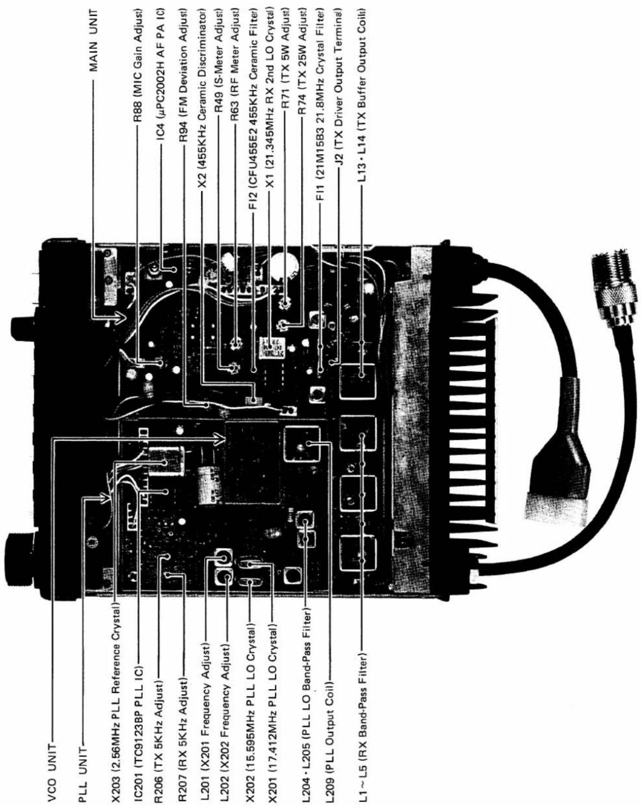
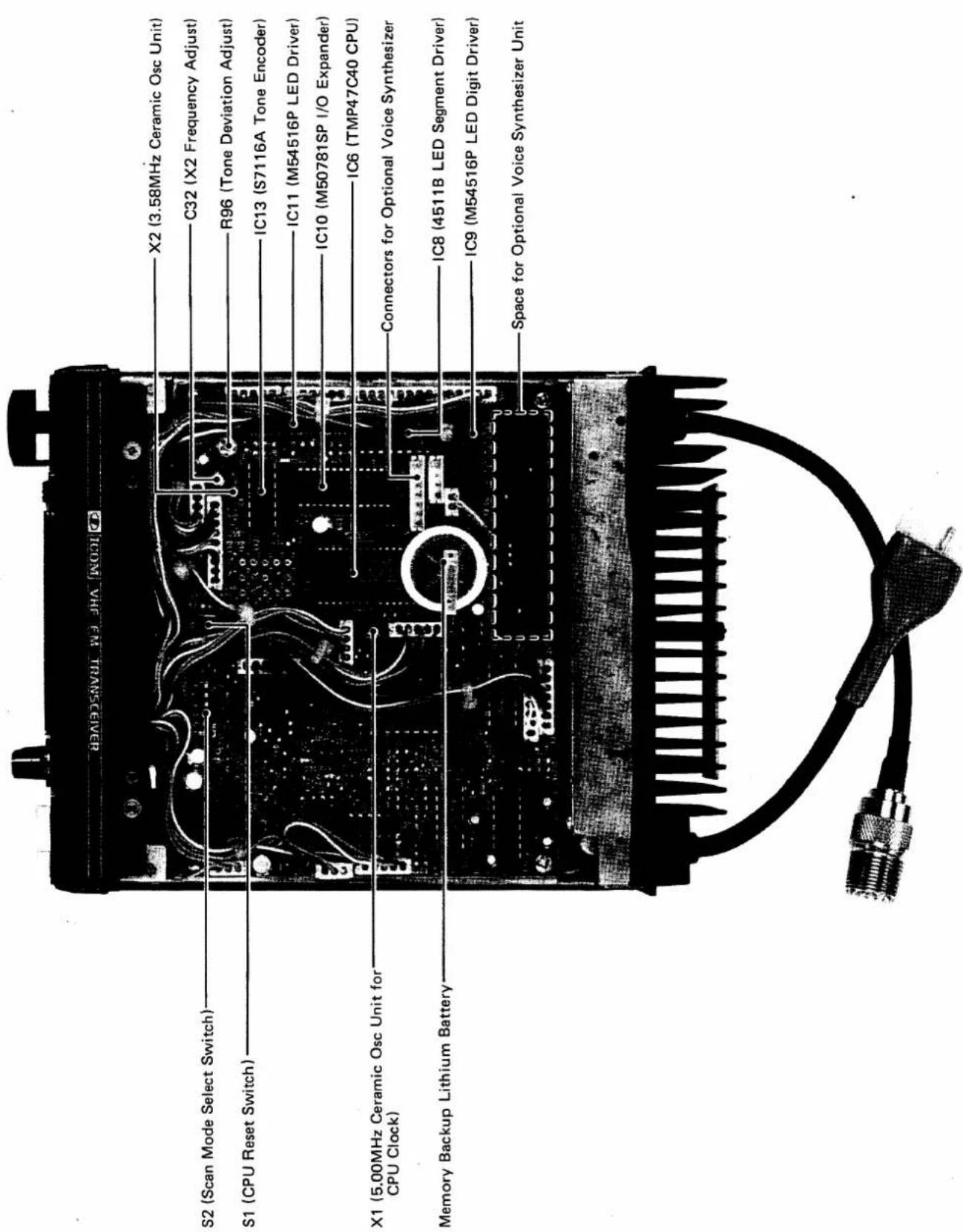
Your IC-37A has been tested very carefully at the factory before shipping. The chart below has been designed to help you correct any problems which are not equipment malfunctions. If you are not able to locate the problem and/or solve it through use of this chart, please contact your dealer or the nearest ICOM service center for assistance.
| Problem | Possible Cause | Solution |
| 1. Power does not come ON when the switch is turned. | Power cord is improperly connected.Power cord is connected with the polarity reversed.Blown fuse. | Carefully reconnect power cord.Disconnect the power cord, replace the blown fuse, then reconnect the power cord observing proper polarity.Check for the cause, then replace the fuse with a new one. |
| 2. No sound comes from the speaker. | VOLUME Control knob is completely counterclockwise, but not “clicked OFF”.The unit is in the transmit mode, by the PTT Switch on the microphone.SQUELCH setting is turned too far clockwise.External speaker is in use.The internal speaker cable is not connected. | Turn the knob clockwise to a suitable level.Put the unit in the receive mode.Turn the SQUELCH control counterclockwise until noise can be heard and reset it just above the threshold.Check if the external speaker plug is inserted properly or if the external speaker cable is cut.Connect the speaker connection. |
| 3. Sensitivity is low and only strong signals are audible. | The antenna feed line is cut or shorted. | Check the feed line and correct any improper condition. |
| 4. No or low RF output. | PTT Switch is not functioning due to bad connection of the MIC connector.The antenna feeder is cut or shorted. | Check the connection of the MIC connector and correct any problems.Check the antenna feeder and correct any problems. |
| 5. No modulation. | Bad connection of the MIC connector.The MIC cable is cut. | Check the connection of the MIC connector and correct any problems.Repair the disconnected or cut wire. |
| 6. The receive mode functions properly and your signals are transmitted, but you are unable to make a contact with another station. | The set is in DUPLEX mode. (When desiring SIMPLEX mode.)The set is in SIMPLEX mode. (When desiring DUPLEX mode.)Improper frequency split or input/output frequency of the repeater. | Push the “DUP+” or “DUP-” button to go off both DUPLEX indicators.Push the “DUP+” or “DUP-” button according to repeater input/output frequency.Set the proper frequency split and push the “DUP+” or “DUP-” button according to the repeater input/output frequency. |
| 7. The memory scan operation does not function when the S/S Switch is pushed. | The set is not in the Memory Channel mode. | Push the VFO/MEMORY Switch for the Memory Channel mode. |
| 8. The programmed scan operation does not function when the S/S switch is pushed. | The set is not in the VFO mode. | Push the VFO/MEMORY Switch for the VFO mode. |
| 9. The scan does not stop even if a signal is received. | The squelch has opened when the scan started. (When SCAN-STOP FUNCTION switch is in BUSY position.) | Engage the squelch on a no signal frequency, then start the scan by pushing the S/S switch. |
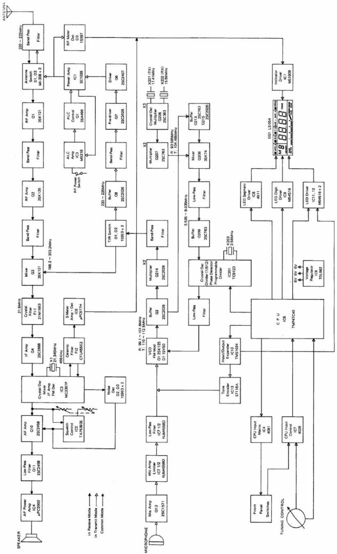
flowchart
graph TD
    A["SPEAKER"] --> B["AF Power Amp IC4 μPC2002"]
    B --> C["Low-Pass Filter Q11 25C2458"]
    C --> D["AF Amp Q10 25C2458"]
    D --> E["Crystal Osc Mixer IF Amp FM Det IC3 MC3357P"]
    E --> F["IF Amp Q4 25C2668"]
    F --> G["Crystal Filter F1-1 21M1583"]
    G --> H["Mixer Q3 3SK121"]
    H --> I["Band-Pass Filter"]
    I --> J["RF Amp Q2 25K125"]
    J --> K["Band-Pass Filter"]
    K --> L["RF Amp Q1 3SK121"]
    L --> M["Antenna Switch D1, D3 MI-308 x 2"]
    M --> N["Band-Pass Filter"]
    N --> O["RF Meter Det D2 15S97"]
    O --> P["ANTENNA"]

    subgraph Inputs
        Q["Squelch Control IC2 TA75393S"] --> E
        R["Noise Det D2, D3 1S953 x 2"] --> E
        S["Ceramic Filter F12 CFU455E2"] --> T["S-Meter Amp > Det IC6 μPC577H"]
        U["Tone Encoder IC13 S7118A"] --> V["VCO FM Mod Q1 25K125 D1 1SV50"]
        W["Input/Output Expander IC10 TMS1024"] --> X["CPU IC6 TMP47C40"]
    end

    subgraph Outputs
        Y["Low-Pass Filter"] --> Z["Buffer Q2 2SC2026"]
        AA["Multiplier Q214 2SC2026"] --> AB["Band-Pass Filter"]
        AC["Low-Pass Filter"] --> AD["CPU IC6 TMP47C40"]
        AE["Power Amp IC1 SC102B"] --> AF["Driver Q6 2SC2407"]
        AG["Multiplier Q207 2SC763"] --> AH["Crystal Osc Multiplier Q206 2SC383"]
        AI["Buffer Q213 2SC763 Q215 2SC2026"] --> AJ["Mixer Q208 3SK74"]
        AK["Buffer Q209 2SC763"] --> AL["Buffer Q209 2SC763"]
        AM["LED Segment Driver IC8 4511"] --> AN["DS1 LS-054"]
        AO["LED Digit Driver IC9 M54516"] --> AP["Indicator Driver IC1 M51909"]
    end

    subgraph Outputs
        AQ["Power Amp IC1 SC102B"] --> AR["Driver Q6 2SC2407"]
        AS["Multiplier Q207 2SC763"] --> AT["X3"]
        AU["Multiplier Q209 2SC763"] --> AV["X3"]
        AW["Low-Pass Filter"] --> AX["Buffer Q209 2SC763"]
        AY["Buffer Q209 2SC763"] --> AZ["X3"]
        BA["Buffer Q213 2SC763 Q215 2SC2026"] --> BB["X3"]
        BC["DDRQ1 TXI 17.41MHz"] --> BD["X3"]
        BE["X3"] --> BF["X3"]
    end
ICOM INCORPORATED
1-6-19, KAMI KURATSUKURI, HIRANO-KU, OSAKA JAPAN
A-0569
Printed in Japan
- TABLE OF CONTENTS
- SECTION I SPECIFICATIONS
- THE MOST COMPACT 220MHz MOBILE
- HIGH OUTPUT POWER
- MEMORIES
- SUBAUDIBLE TONE ENCODER
- MULTI-PURPOSE SCANNING
- PRIORITY SCANNING
- SPEECH SYNTHESIZER
- SECTION III INSTALLATION
- UNPACKING
- LOCATION
- POWER REQUIREMENTS
- ANTENNA
- MICROPHONE
- EXTERNAL SPEAKER
- FRONT PANEL
- 1: VFO/MEMORY SWITCH
- VFO SWITCH
- TUNING CONTROL
- SCAN START/STOP BUTTON
- TUNING RATE SWITCH
- 1MHz UP BUTTON
- MEMORY WRITE/OFFSET CHECK BUTTON
- OFFSET WRITE BUTTON
- -DUPLEX BUTTON
- +DUPLEX BUTTON
- SPEECH SYNTHESIZER SWITCH
- PRIORITY SWITCH
- SQUELCH CONTROL
- VOLUME CONTROL and POWER SWITCH
- MIC CONNECTOR
- RF POWER SWITCH
- TONE SELECT BUTTON
- FREQUENCY DISPLAY
- MEMORY CHANNEL DISPLAY
- S/RF INDICATOR
- VFO INDICATOR
- RECEIVE INDICATOR
- TRANSMIT INDICATOR
- DUPLEX INDICATOR
- TONE INDICATOR
- REAR PANEL
- EXTERNAL SPEAKER JACK
- ANTENNA CONNECTOR
- POWER CONNECTOR
- UNDER THE ACCESS COVER
- CPU RESET SWITCH
- SCAN SPEED SWITCH
- SCAN-STOP TIMER SWITCH
- SCAN-STOP INTERVAL SWITCH
- VFO-SCAN MODE SWITCH
- SCAN-STOP FUNCTION SWITCH
- HOW TO TUNE
- PRESET FREQUENCY
- TUNING CONTROL
- VFO/MEMORY SWITCH and VFO SWITCH
- FOR EXAMPLE:
- DUPLEX (REPEATER) OPERATION
- RESETTING THE OFFSET FREQUENCY
- MEMORY CHANNEL OPERATION
- MEMORY CHANNEL SELECTION
- MEMORY-WRITE (PROGRAMMING THE MEMORY CHANNELS)
- TUNING BY UP/DOWN BUTTONS ON THE MICROPHONE
- FREQUENCY CONTROL
- SCANNING OPERATION
- MEMORY SCAN
- PROGRAMMED SCAN
- VFO FULL RANGE SCAN
- RESUMING SCAN
- PRIORITY FUNCTION
- TONE ENCODER OPERATION
- OPERATION
- RECEIVING
- TRANSMITTING
- MAIN UNIT SIDE
- ICOM INCORPORATED
Marke : ICOM
Modell : IC-37A
Kategorie : Empfänger