
IC-3PS - Empfänger ICOM - Kostenlose Bedienungsanleitung
Finden Sie kostenlos die Bedienungsanleitung des Geräts IC-3PS ICOM als PDF.


| Produkttyp | Netzteil / Lautsprecherständer für tragbare Transceiver |
| Marke | ICOM |
| Modell | IC-3PS |
| Abmessungen (H × B × T) | 188 mm × 122 mm × 150 mm |
| Gewicht | ca. 2,3 kg |
| Eingangsspannung | 117 V oder 240 V AC, 50/60 Hz |
| Ausgangsspannung | 13,8 V DC, negative Masse |
| Maximaler Ausgangsstrom | 3 A (Dauerbetrieb) |
| Schutzschaltung Ansprechstrom | 4,5 A ±10 % |
| Restwelligkeit | weniger als 10 mV bei 3 A Last |
| Spannungsregelung | ±3 % bei Nenneingangsspannung ±10 %; weniger als −3 % bei 3 A Last |
| Funktionen | Externes Netzteil, Lautsprecher, Standfuß, Aufnahme für Linearverstärker (IC-50L, IC-20L, IC-30L) |
| Anschlüsse | Netzeingang, Lautsprecherausgang, externer Stromausgang (13,8 V) |
| Lieferumfang | Netzkabel, Lautsprecherkabel, Netzstecker, Sicherungen (1 A für 240 V, 2 A für 117 V), Gummifüße |
| Sicherheit | Überstromschutz (automatische Abschaltung bei Kurzschluss) |
| Wartung | Keine besondere Wartung erforderlich; Sicherungen bei Bedarf ersetzen |
| Ersatzteile | Sicherungen (1 A und 2 A) als Zubehör erhältlich |
Häufig gestellte Fragen - IC-3PS ICOM
Benutzerfragen zu IC-3PS ICOM
0 Frage zu diesem Gerät. Beantworten Sie die, die Sie kennen, oder stellen Sie Ihre eigene.
Eine neue Frage zu diesem Gerät stellen
Laden Sie die Anleitung für Ihr Empfänger kostenlos im PDF-Format! Finden Sie Ihr Handbuch IC-3PS - ICOM und nehmen Sie Ihr elektronisches Gerät wieder in die Hand. Auf dieser Seite sind alle Dokumente veröffentlicht, die für die Verwendung Ihres Geräts notwendig sind. IC-3PS von der Marke ICOM.
BEDIENUNGSANLEITUNG IC-3PS ICOM
INSTRUCTION MANUAL
AC POWER SUPPLY
IC-3PS
50MHz 10W LINEAR AMPLIFIER
IC-50L
144MHz 10W LINEAR AMPLIFIER
IC-20L
430MHz 10W LINEAR AMPLIFIER
IC-30L

ICOM
TABLE OF CONTENTS
PROFILE 2
SPECIFICATIONS 4
ACCESSORIES. 6
PARTS DESIGNATION (IC-3PS)....7
HOW TO USE THE IC-3PS 8
PARTS DESIGNATION (IC-50L, IC-20L, IC-30L).... 11
THEORY OF OPERATION.... 17
SCHEMATIC DIAGRAM.... 20
OPTIONS 24
Congratulations on the purchase of this ICOM product. This instruction manual collectively gives descriptions of the IC-3PS Power Supply and IC-50L, IC-20L, and IC-30L Linear Amplifiers, to provide the information you need when using them. Please read these instructions carefully to receive full value and maximum performance of the set.
natural_image
Black-and-white photo of a vintage electronic device with control panel and microphone, no visible text or symbols on the device itself.PROFILE
IC-3PS
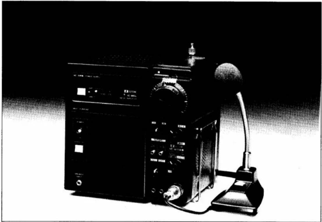
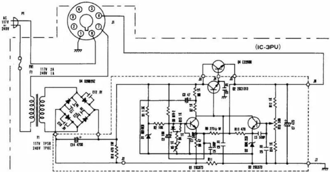
The IC-3PS is an AC power supply/speaker stand to hold the IC-3PU AC power supply and the linear amplifier (IC-50L, IC-20L, IC-30L) inside and to power the portable transceiver (IC-502, IC-202, IC-215/E, IC-202E, IC-202S, and the IC-402) providing a convenient fixed station. It supplies a regulated DC voltage of 13.8 Volts from an AC 117 or 240V source to the portable transceiver as an external power source, and also serves as a stand for the transceiver, a mount case for the linear amplifier, and an external speaker.
IC-50L, IC-20L, IC-30L
The linear amplifier is connected to the portable transceiver and increases its output from 3 Watts to 10 Watts.
SMALL SIZE, LIGHT WEIGHT
Because of it's small size and light weight, the amplifier can be mounted easily in a small space in the IC-3PS or in a car.
The DC voltage for T/R switching control is superimposed on the RF coaxial cable. This permits the amplifier to be controlled by only connecting the coaxial cable from the transceiver. Unlike the carrier control method, no cutoff of the initial transmission occurs.
POWER CONNECTOR SOCKET
As a power connector socket is provided, only one power cord is necessary for battery or external power connections. This provides neat wiring when mounted in a car.
LARGE SIZED HEAT SINK
The large sized extruded aluminum heat sink provides excellent heat dissipation to maintain a stabilized output during long periods of operation.
APC CIRCUIT
When the antenna circuit is open or shorted or when the SWR is extremely high, the APC circuit works to inactivate the linear amplifier to protect the final stage transistor.
DIRECT CIRCUIT
When the power switch of the linear amplifier is turned to the DIRECT (OFF) position, the amplifier circuit is bypassed and the 3 Watt output of the transceiver is fed directly to the antenna.
SPECIFICATIONS
| IC-3PS AC POWER SUPPLY | IC-50L 50MHz LINEAR AMPLIFIER | ||
| Number of Semiconductor | Transistors 4Diodes 5 | Number of Semiconductor | Transistors 6Diodes 11 |
| Rated Input Voltage | 117V or 240V AC 50/60Hz | Frequency Coverage | 50 ~ 51MHz |
| Input Voltage Tolerance | Within ±10% of the rated input voltage | Acceptable ModulationPower Supply Requirements | SSB · CW · AM · FM13,8V DC ±15% |
| Output Voltage | 13.8V DC Negative Grounded | Negative Ground 3A Max. | |
| Output Voltage Regulation | Within ±3% even with the rated input voltage ±10%Less than -3% with 3A load at rated input voltage | Current Drain | Approx 1.7A at CW 10WOutputApprox 15mA at Stand by 3 Watts P.E.P. |
| Ripple Voltage | Less than 10mV with 3A' load at rated input voltage | Drive Power RequirementsOutput PowerInput Impedance | 10 Watts P.E.P.50Ω Unbalanced |
| Maximum Load Current | 3A (Continuous Duty) | Output (Load) ImpedanceDimensions | 50Ω Unbalanced49mm(H) x 102mm(W) x 141mm(D) |
| Protection Circuit Operating | |||
| Current | 4.5A ±10% | ||
| Dimensions | 188mm(H) x 122mm(W) x 150mm(D) | WeightAccessories | Approx 0.8kgPower Cord....1 |
| Weight | Approx. 2.3kg | Power Connector Cord(2P-2P)....1 | |
| Accessories | Speaker Cord....1Power Plug....1Fuse (1A/2A)....2Rubber Fixing Base....1 | Coaxial Cable....1Fuse (5A)....2 | |
IC-20L 144MHz LINEAR AMPLIFIER
| Number of Semiconductors | Transistors 6Diodes 11 |
| Frequency Coverage | 144~146MHz |
| Acceptable Modulation | SSB·CW·AM·FM |
| Power Supply Requirements | 13.8V DC ±15%Negative Ground 3A Max. |
| Current Drain | Approx. 1.8A at CW 10WOutputApprox. 15mA at stand by |
| Drive Power Requirements | 3 Watts P.E.P. |
| Output Power | 10 Watts P.E.P. |
| Input Impedance | 50Ω Unbalanced |
| Output (Load) Impedance | 50Ω Unbalanced |
| Dimensions | 49mm(H) x 102mm(W) x 141mm(D) |
| Weight | Approx 0.8kg |
| Accessories | Power Cord . . . . . . . . . . . . . . . . . . . . . . . . . . . . . . . . . . . . . . . . . . . . . . . . . . . . . . . . . . . . . . . . . . . . . . . . . . . . . . . . . . . . . . . . . . . . . . . . . . . . |
| Power Connector Cord(2P-2P) . . . . . . . . . . . . . . . . . . . . . . . . . . . . . . . . . . . . . . . . . . . . . . . . . . . . . . . . . . . . . . . . . . . . . . . . . . . . . . . . . . . . . . . . . . . . . . . . . . . (3P-2P) . . . . . . . . . . . . . . . . . . . . . . . . . . . . . . . . . . . . . . . . . . . . . . . . . . . . . . . . . . . . . . . . . . . . . . . . . . . . . . . . . . . . . . . . . . . . . . Coaxial Cable . . . . . . . . . . . . . . . . . . . . . . . . . . . . . . . . . . . . . . . . . . . . . . . . . . . . . . . . . . . . . . . . . . . . . . . . . . . . . . . . . . . . . . . . . . . . Fuse (5A) . . . . . . . . . . . . . . . . . . . . . . . . . . . . . . . . . . . . . . . . . . . . . . . . . . . . . . . . . . . . . . . . . . . . . . . . . . . . . . . . . . . . . . . . . . . . . . . . . . |
IC-30L 430MHz LINEAR AMPLIFIER
| Number of Semiconductors | Transistors | 7 | |
| Diodes | 9 | ||
| IC | 1 | ||
| Frequency Coverage | 430~435.2MHz | ||
| Acceptable Modulation | SSB·CW·AM·FM | ||
| Power Supply Requirements | 13.8V DC ±15% | ||
| Negative Ground 3A Max. | |||
| Current Drain | Approx. 1.8A at CW 10W Output | ||
| Approx. 25mA at stand by | |||
| Drive Power Requirements | 3 Watts P.E.P. | ||
| Output Power | 10 Watts P.E.P. | ||
| Input Impedance | 50Ω Unbalanced | ||
| Output (Load) Impedance | 50Ω Unbalanced | ||
| Dimensions | 49mm(H) x 102mm(W) x 141mm(D) | ||
| Weight | Approx 0.8kg | ||
| Accessories | Power Cord . . . . . . . . . . . . . . . . . . . . . . . . . . . . . . . . . . . . . . . . . . . . . . . . . . . . . . . . . . . . . . . . . . . . . . . . . . . . . . . . . . . . . . . . . . . . . . . . . . . . | ||
| Power Connector Cord (3P-2P) . . . . . . . . . . . . . . . . . . . . . . . . . . . . . . . . . . . . . . . . . . . . . . . . . . . . . . . . . . . . . . . . . . . . . . . . . . . . . . . . . . . . . . . . . . . . . . . . . . . .. | |||
| Coaxial Cable . . . . . . . . . . . . . . . . . . . . . . . . . . . . . . . . . . . . . . . . . . . . . . . . . . . . . . . . . . . . . . . . . . . . . . . . . . . . . . . . . . . . . . . . . . . . . . . . . . . Fuse (5A) . . . . . . . . . . . . . . . . . . . . . . . . . . . . . . . . . . . . . . . . . . . . . . . . . . . . . . . . . . . . . . . . . . . . . . . . . . . . . . . . . . . . . . . . . . . . . . . . . . | |||
ACCESSORIES
IC-3PS
natural_image
Product diagram showing a black rectangular device with four labeled parts: two connected cables and three small accessories (no text or symbols present)- IC-50L · IC-20L · IC-30L
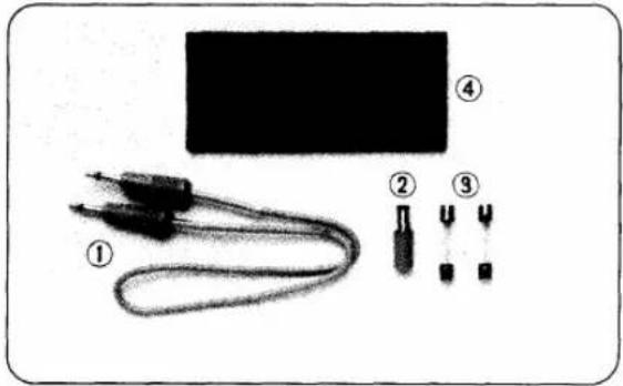
① Speaker Cord
② Power Plug
③ Fuses (1A for 240V, 2A for 117V)
④ Rubber Fixing Base
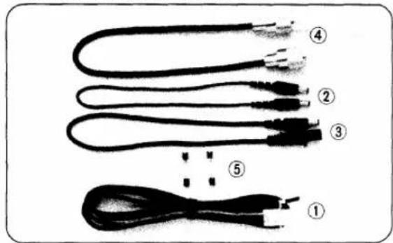
① Power Cord
② Power Connector Cord (2P - 2P) (Not include for IC-30L)
③ Power Connector Cord (3P - 2P) (Not include for IC-50L)
④ Coaxial Cable
⑤ Fuses (5A)
PARTS DESIGNATION (IC-3PS)
FRONT SIDE
REAR SIDE
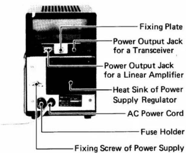
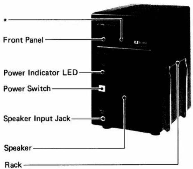
*Remove the protective sheet attached to the front panel before use.
HOW TO USE THE IC-3PS
WHEN USED AS A TRANSCEIVER STAND
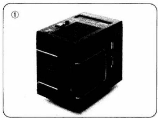
① TO ATTACH THE TRANSCEIVER TO THE RIGHT SIDE
Pull out the rack on the right side of the IC-3PS to its full span and place the transceiver in between the rack and the IC-3PS.
② TO ATTACH THE TRANSCEIVER TO THE LEFT SIDE
Detach the rack by loosening the two screws holding the rack holder and transfer the rack and holder to the left side. As tapped holes are also provided on the left side, attach the rack there by securing it with the screws. Then pull out the rack and install the transceiver as before.
Since the speaker of the transceiver faces the side of the IC-3PS in this case, use the speaker of the IC-3PS (see page 9).
natural_image
Black industrial electronic device with no visible text or symbols on its body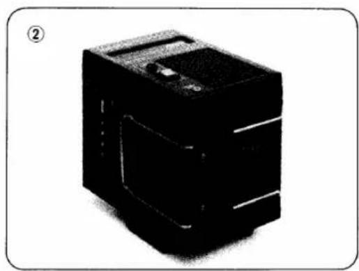
natural_image
Black industrial electronic device with internal components, no visible text or symbolsFIXING THE TRANSCEIVER TO THE IC-3PS
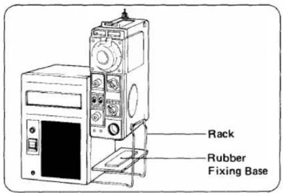
A rubber base is provided to prevent the transceiver from sliding back and forth when attached to the IC-3PS. Fix the transceiver, as shown in the following drawing, with its recess on the bottom fitted into the convex of the rubber base and the recess of the base fitted to the rack.
WHEN USED AS AN EXTERNAL SPEAKER
Since the speaker of the transceiver is on the side plate, use the external speaker of the IC-3PS. Connect the external Speaker jack (EXT SP) of the transceiver and the Speaker Input jack of the IC-3PS with the accessory speaker cord.
CAUTION: Be sure to switch OFF the power supply to the transceiver before connecting the speaker cord. If connected with the power supply turned ON, damage may be caused to the audio IC of the transceiver.
WHEN USED AS AN AC POWER SOURCE
Connecting the power output jack of the IC-3PS to the external power jack of the transceiver with the accessory power connector cord, after turning OFF the respective Power switch and Function switch.
CAUTION: The accessories of the IC-20L include a power connector cord (3P - 2P). When you want to use the IC-3PS in combination with the IC-202S transceiver, use this power connector cord.
In case you already have an IC-20L and purchase an IC-202S, a power connector cord (3P - 2P) will be necessary. This is available as an option from your ICOM distributor/dealer. (Code name: OPC-003, length: 35cm).
OPERATION
Plug the AC power cord into a 117 or 240 Volt AC outlet and turn ON the power switch of the IC-3PS. This will light the red power indicator LED. Then turn ON the function switch of the transceiver. This will apply power to the transceiver and light its power indicator LED.
If the transceiver fails to be powered when the indicator of the IC-3PS is lit, turn OFF both the power switches and check for defective contacts of the plugs, jacks, etc. and for broken cord wires. Correct the problem, then turn ON the switches again.
If the power indicator LED of the IC-3PS fails to light when the power switch is turned ON, turn OFF the switch and check for sported plugs. Remove the short, then turn ON the switch again. (If the plugs short, an automatic Protection circuit inside the IC-3PU is activated and the output voltage is reduced to "0".)
PARTS DESIGNATION (IC-50L, IC-20L, IC-30L)
The IC-50L, IC-20L, IC-30L, differ from each other in frequency band, but are similar in appearance. The description given will be mainly of the IC-50L
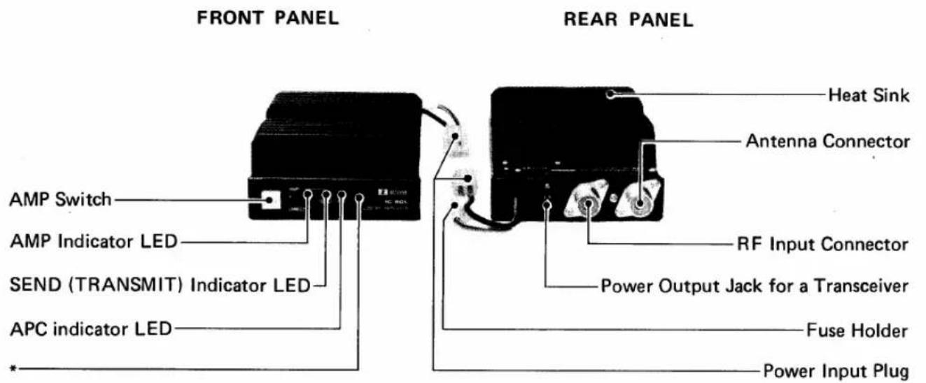
*Remove the protective sheet attached to the front panel before using.
HOW TO USE THE LINEAR AMPLIFIER
MOUNTING THE LINEAR AMPLIFIER
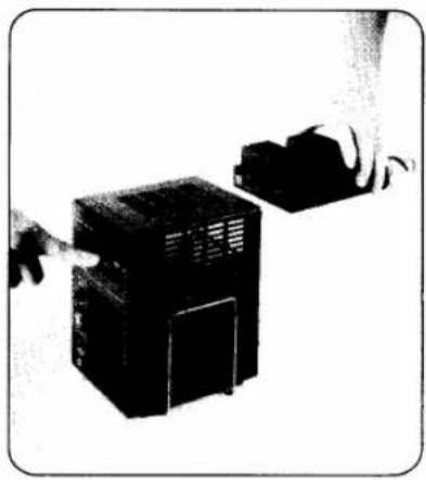
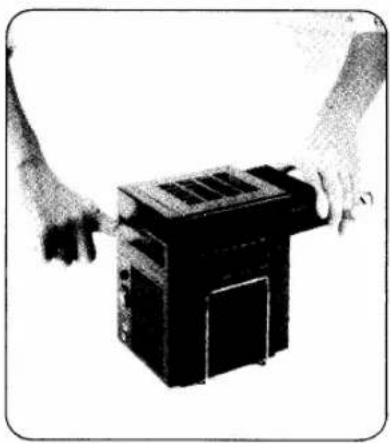
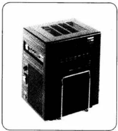
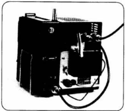
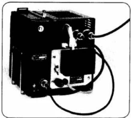
Remove the fixing plate on the back of the IC-3PS. Insert the amplifier from the rear while depressing the front panel of the IC-3PS, as shown in the photos. (To facilitate the work, insert the amplifier with its front pointed slightly downward). After the amplifier has been sungly fit in, replace the fixing plate so that its folded portion fits in the notch on the amplifier and tighten the screw. Then connect the power cord, coaxial cable etc., as shown below.
natural_image
Two hands inserting a black electronic device into a larger housing (no text or symbols visible)- Depress the front panel from the front.
natural_image
Two hands holding a black industrial machine component (no visible text or symbols)- Insert the linear amplifier.
natural_image
Black-and-white photo of a desktop computer tower with ventilation grilles and front panel (no visible text or labels)- Completed.
CABLE CONNECTION
FOR IC-502 · IC-202 · IC-202E · IC-215
natural_image
Black-and-white photo of an electronic device with wires and components (no visible text or symbols)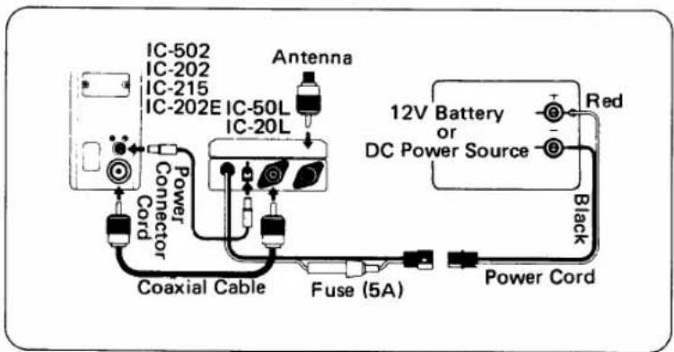
FOR IC-202S
natural_image
Black industrial electrical device with wires and connectors (no visible text or symbols)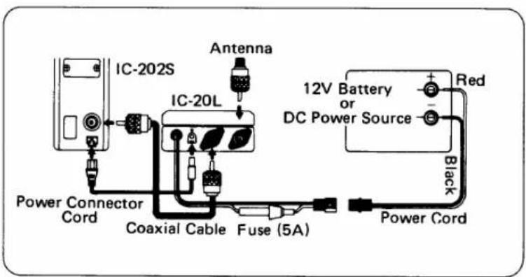
FOR IC-402
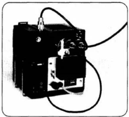
natural_image
Black-and-white photo of an electrical contactor with wires and connectors (no visible text or symbols)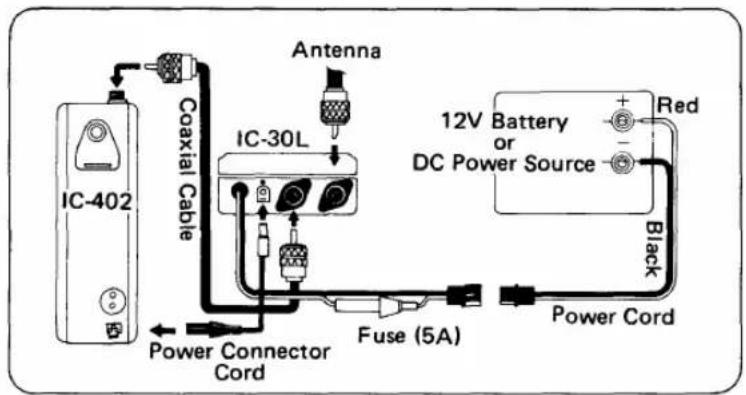
HOW TO USE THE LINEAR AMPLIFIER
After mounting the linear amplifier, connect a microphone or key to the transceiver. Then set the power switches of the IC-3PS unit and transceiver to the OFF position and the AMP switch of the linear amplifier to the DIRECT (OFF) position. Plug the AC power cord into an AC outlet and turn ON the power switch. This will light the power indicator LED of the IC-3PS.
Now your transceiver set is ready to use. If you turn ON the function switch of the transceiver, the indicator of the transceiver will light, and noise or audio will be heard from the speaker showing that the set is in receive. If you switch to transmit from this condition, the 3 Watt output of the transceiver is directly applied to the antenna.
If the AMP switch is placed in the AMP position with the transceiver in receive, the AMP indicator LED will light showing that the linear amplifier is powered. In the receive mode, the antenna is connected directly to the transceiver.
If the transceiver is switched to transmit, the SEND (TRANSMIT) indicator LED will light indicating that the linear amplifier is also switched to transmit. In this case, an amplified output of 10 Watts is applied to the antenna.
USING A POWER SUPPLY OTHER THAN THE IC-3PS.
If you want to use a power supply other than the IC-3PS, use a regulated supply giving 13.8 Volts and more than 3A current capacity. Connect the cables as shown in the drawings on page 13. Be careful to observe the correct polarity of the power supply. Connect the red lead to the (+) positive terminal and the black lead to the (−) negative terminal of the power supply. Reverse connection results in blowing the fuse in the protective circuit of the linear amplifier. Should this occur, correct the power connection and replace the fuse (5 Amp). Make sure that the supply voltage is within the range of 13.8 Volts ±15% in both transmit as well as receive.
APC CIRCUIT
If the SWR becomes high due to antenna trouble or poor matching, the APC circuit will work and turn OFF the SEND indicator LED and light the APC indicator LED. In this condition, the linear amplifier will not switch ON (to the transmit state), thus protecting the power amplifier transistor. When the APC circuit is activated, the transceiver output is directly fed to the antenna. This prevents communication from being completely interrupted even when the SWR is high.
However, with the IC-50L and the IC-20L, set the AMP switch to the DIRECT position and then check the antenna and feeder and remove any trouble before continuing operation. In the IC-30L, the switch may remain in the AMP position while checking for trouble before continuing operation.
If you connect a receive pre-amp to the amplifier, one that depends on a carrier for T/R switching, the APC may work due to a time lag caused by T/R switching.
CAUTION:
Note that if the Function switch of the transceiver is turned OFF with the AMP switch of the IC-50L or IC-20L set to the AMP position, the IC-50L and IC-20L is switched to the transmit mode, though no RF is emitted. The IC-30L is not switched to the transmit mode even if the IC-402 is turned OFF.
MOBILE INSTALLATION
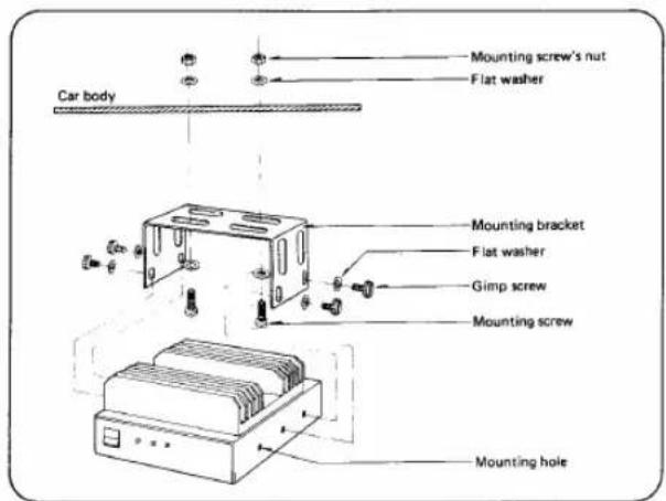
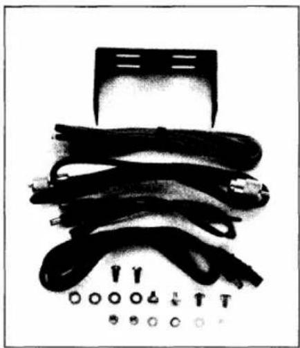
Connect the cables as shown in the drawing using the mobile mounting bracket, available as an option. The three mounting holes on the side of the amplifier allow adjustable mounting. Using the center and the rear holes will extend the amplifier forward, while using the center and forward holes will extend the amplifier to the back of the holder. The transceiver and linear amplifier may be separated by a distance of about one meter. Therefore, it is possible to set the transceiver near the driver's seat and place the linear amplifier under the seat.
THEORY OF OPERATION
IC-50L, IC-20L
POWER AMPLIFIER CIRCUIT
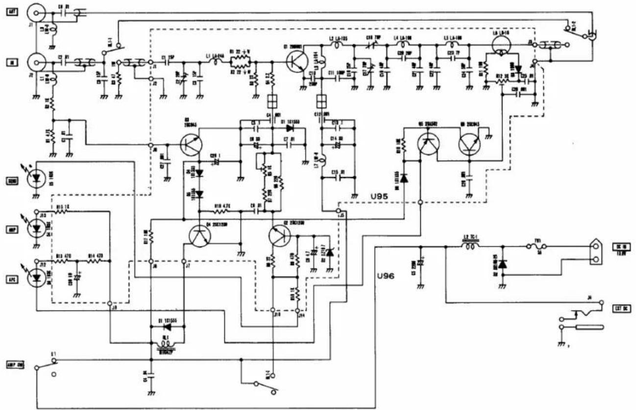
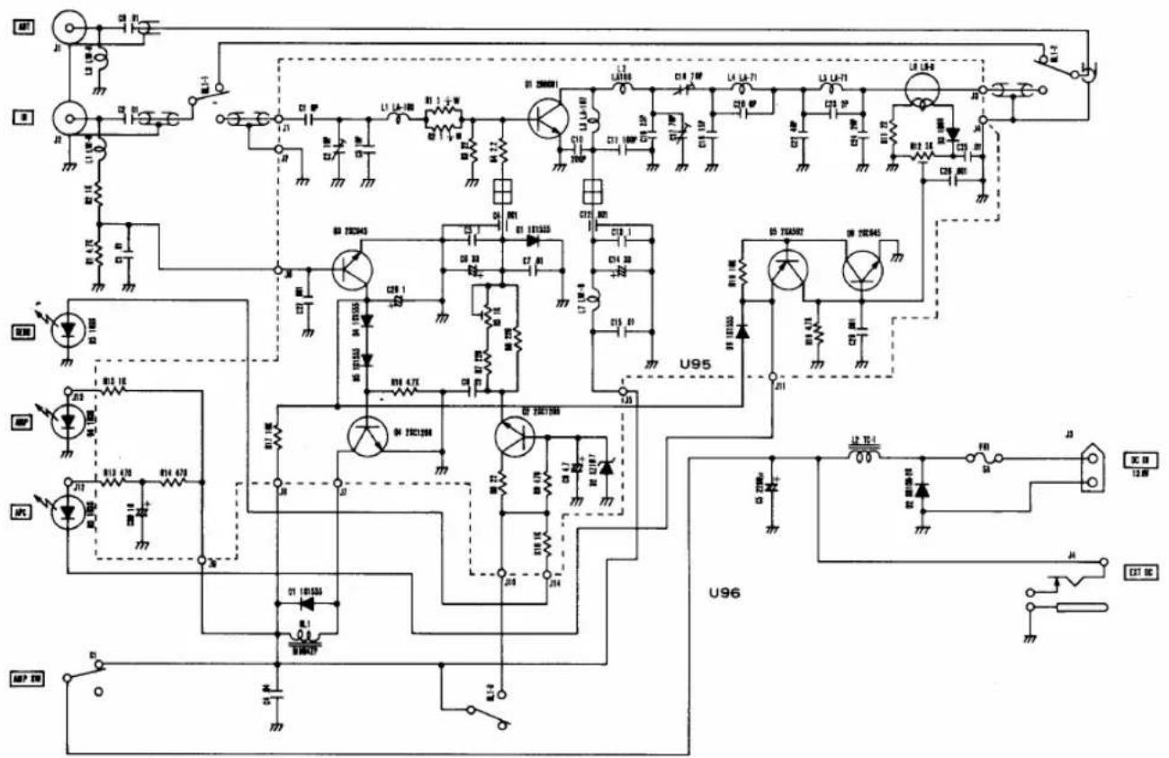
The 3 Watt input from the transceiver is fed to the base of Q1 through relay RL2, and after being amplified by Q1 and harmonics suppressed by an M-derived filter, applied to the external antenna through relay RL1 as a 10 Watt output with very little spurious.
DIRECT CIRCUIT
The transceiver is directly connected to the external antenna when the IC-3PS is switched OFF, when the APC circuit is activated, or when in the receive mode.
BIAS CIRCUIT
A linear amplifier is susceptible to thermal runaway due to the bias given to the transistor. The amplifier prevents the variation of bias current by preventing variation of the supply voltage with a voltage regulator circuit consisting of D2 and Q2 and by temperature compensation of the bias control of Q1 by D1.
T/R SWITCHING CIRCUIT
In receive, about 4 Volts DC from the transceiver is superimposed on the coaxial cable. This voltage is taken out through L1 and fed to switching circuits Q3 and Q4. During receive, Q3 is ON and Q4 is OFF, and relay RL1 is in activated giving a direct antenna connection. When switched to transmit, Q3 is turned OFF and Q4 turned ON, and relay RL1 activates the power amplifier. At the same time, the SEND indicator LED is lit.
APC CIRCUIT
In the amplifier, the SWR detector, incorporated in the antenna circuit, detects reflected waves. When a mismatch occurs, the detected RF is rectified by D3, and the DC voltage is fed to the base of Q6 and keeps Q5 and Q6 ON. This switches OFF Q4 through D6 and returns relay RL1 to DIRECT, to protect Q1. At the same time, the APC indicator LED is lit.
IC-30L
POWER AMPLIFIER
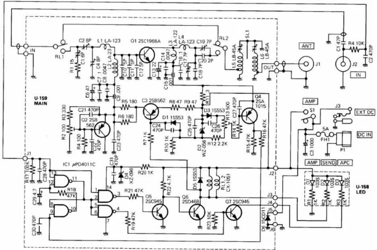
The 3 Watt input from the transceiver is fed to the base of Q1 through coaxial relay RL1, then amplified by Q1 and fed through coaxial relay RL2 and a helical Band Pass Filter for harmonic suppression. It is then applied to the external antenna as a 10 Watt output with very little spurious. C1 and R1 provided in the input circuit controls driving power to give 10 Watt output.
DIRECT CIRCUIT
The transceiver is directly connected to the external antenna through the helical Band Pass Filter when the amplifier is switched OFF, when the APC is activated, or when in the receive mode. Here, the loss is about 0.4 dB including the connector and filter.
BIAS VOLTAGE REGULATOR CIRCUIT
A linear amplifier is susceptible to thermal runaway due to the bias current given to the transistor. The amplifier prevents variation of bias current by preventing variation of the supply voltage, by means of Q3, and by temperature compensating the bias control of Q1 by Q2. Q2 feeds the regulated bias voltage to Q1.
APC CIRCUIT
The APC circuit of this amplifier works only against over current because a final stage transistor of high puncture resistance is used (resistant to all phases of VSWR under infinite load when Vcc=15.2 Volts, f=470MHz, Po=18 Watts).
The voltage drop of R11 connected to the collector of Q1 is switched by Q4 and applied to the APC control circuit to effect detection.
APC CONTROL, T/R SWITCHING CIRCUIT
APC is controlled by a flip flop composed of two sets of NAND gates. This is usually reset in the receive mode and Pin 11 of IC1 is brought to a HIGH level. In the transmit mode, Pin 3 of IC1 brought to a LOW level, Q5 is turned OFF and Q6 turned ON, and coaxial relays RL1, RL2 activate and the power amplifier circuit will work. At the same time, the SEND indicator LED is lit.
If the APC circuit operates, Pin 11 of IC1 is brought to a LOW level and Q6 is cut OFF, relays RL1 and RL2 deactivate, causing a direct connection to the antenna. Since Pin 4 of IC1 is brought to a HIGH level, Q7 is turned ON and the APC indicator LED lights.
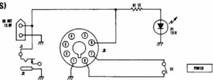
SCHEMATIC DIAGRAM
(IC - 3PS)
(IC - 50L)
(IC - 20L)
(IC - 30L)
OPTIONS
natural_image
Black-and-white photo of various cable and connector components (no text or symbols visible)MOBILE MOUNTING KIT FOR IC-50L, IC-20L OR IC30L
natural_image
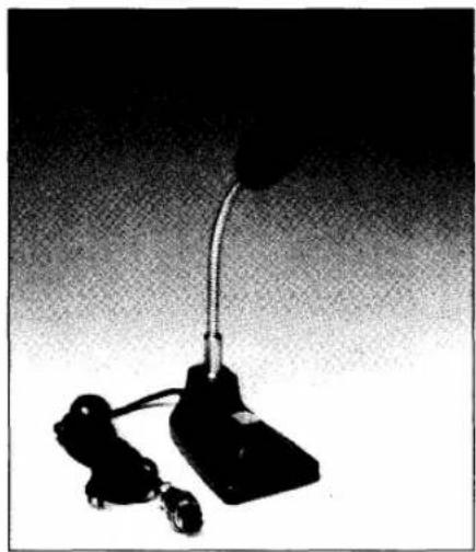
Black-and-white photo of a desk lamp with a curved arm and two wheels, no visible text or symbols.IC-SM2 DESK MICROPHONE ELECTRET CONDENSER TYPE WITH PRE-AMP

ICOM
ICOM INCORPORATED
1-6-19, KAMI KURATSUKURI, HIRANO-KU, OSAKA JAPAN
Printed in Japan
- INSTRUCTION MANUAL
- TABLE OF CONTENTS
- PROFILE
- IC-3PS
- IC-50L, IC-20L, IC-30L
- SMALL SIZE, LIGHT WEIGHT
- POWER CONNECTOR SOCKET
- LARGE SIZED HEAT SINK
- APC CIRCUIT
- DIRECT CIRCUIT
- ACCESSORIES
- PARTS DESIGNATION (IC-3PS)
- HOW TO USE THE IC-3PS
- WHEN USED AS A TRANSCEIVER STAND
- ① TO ATTACH THE TRANSCEIVER TO THE RIGHT SIDE
- ② TO ATTACH THE TRANSCEIVER TO THE LEFT SIDE
- FIXING THE TRANSCEIVER TO THE IC-3PS
- WHEN USED AS AN EXTERNAL SPEAKER
- WHEN USED AS AN AC POWER SOURCE
- OPERATION
- PARTS DESIGNATION (IC-50L, IC-20L, IC-30L)
- HOW TO USE THE LINEAR AMPLIFIER
- MOUNTING THE LINEAR AMPLIFIER
- CABLE CONNECTION
- USING A POWER SUPPLY OTHER THAN THE IC-3PS.
- CAUTION:
- MOBILE INSTALLATION
- THEORY OF OPERATION
- IC-50L, IC-20L
- POWER AMPLIFIER CIRCUIT
- BIAS CIRCUIT
- T/R SWITCHING CIRCUIT
- IC-30L
- POWER AMPLIFIER
- BIAS VOLTAGE REGULATOR CIRCUIT
- APC CONTROL, T/R SWITCHING CIRCUIT
- SCHEMATIC DIAGRAM
- OPTIONS
- ICOM INCORPORATED
Marke : ICOM
Modell : IC-3PS
Kategorie : Empfänger