
IC-475H - Empfänger ICOM - Kostenlose Bedienungsanleitung
Finden Sie kostenlos die Bedienungsanleitung des Geräts IC-475H ICOM als PDF.


| Produkttyp | 430-MHz-All-Mode-Transceiver |
| Marke | ICOM |
| Modell | IC-475H |
| Frequenzbereich | 430,0000 – 450,0000 MHz (US-Version) |
| Betriebsarten | FM, USB, LSB, CW |
| Sendeleistung | 10 – 75 W (einstellbar) |
| Stromversorgung | 13,8 V DC ±15 %; max. 20 A bei 75 W Sendung |
| Abmessungen (B×H×T) | 241 × 95 × 239 mm (mit Vorsprüngen 244 × 108 × 277 mm) |
| Gewicht | 6,0 kg |
| Speicherkanäle | 99 programmierbare Kanäle + P1, P2 und Rufkanal |
| Frequenzstabilität | ±5 ppm (0 °C bis +50 °C) |
| Antennenimpedanz | 50 Ω (unsymmetrisch) |
| Empfangsempfindlichkeit (FM) | <0,18 μV für 12 dB SINAD |
| Empfangsempfindlichkeit (SSB/CW) | <0,1 μV für 10 dB S/N |
| Selektivität (FM) | 15,0 kHz/‐6 dB, 30,0 kHz/‐60 dB |
| Selektivität (SSB/CW) | 2,3 kHz/‐6 dB, 4,0 kHz/‐60 dB |
| Frequenzsynthese | DDS (Direct Digital Synthesizer) mit 5 ms Einschwingzeit |
| Besondere Funktionen | PBT, Notch-Filter, RIT, CI-V-Fernsteuerung, Sprachkompressor, mehrere Scan-Modi |
| Mikrofonimpedanz | 600 Ω |
| Audioausgangsleistung | >2 W an 8 Ω bei 10 % Klirrfaktor |
| Reinigung | Mit trockenem, weichem Tuch; keine aggressiven Reinigungsmittel |
| Optionen | UT-34 (Tonerauschsperre), UT-36 (Sprachsynthesizer), FL-32A (CW-Schmalbandfilter), CR-64 (Hochstabilquarz), AG-35 (Vorverstärker), CT-17 (CI-V-Pegelwandler) |
Häufig gestellte Fragen - IC-475H ICOM
Benutzerfragen zu IC-475H ICOM
0 Frage zu diesem Gerät. Beantworten Sie die, die Sie kennen, oder stellen Sie Ihre eigene.
Eine neue Frage zu diesem Gerät stellen
Laden Sie die Anleitung für Ihr Empfänger kostenlos im PDF-Format! Finden Sie Ihr Handbuch IC-475H - ICOM und nehmen Sie Ihr elektronisches Gerät wieder in die Hand. Auf dieser Seite sind alle Dokumente veröffentlicht, die für die Verwendung Ihres Geräts notwendig sind. IC-475H von der Marke ICOM.
BEDIENUNGSANLEITUNG IC-475H ICOM
10-475H
430MHz ALL MODE TRANSCEIVER
INSTRUCTION MANUAL
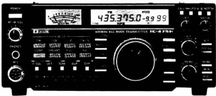
FRONT PANEL

A
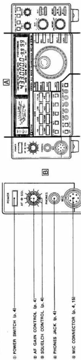
B
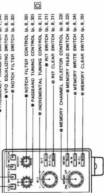
D
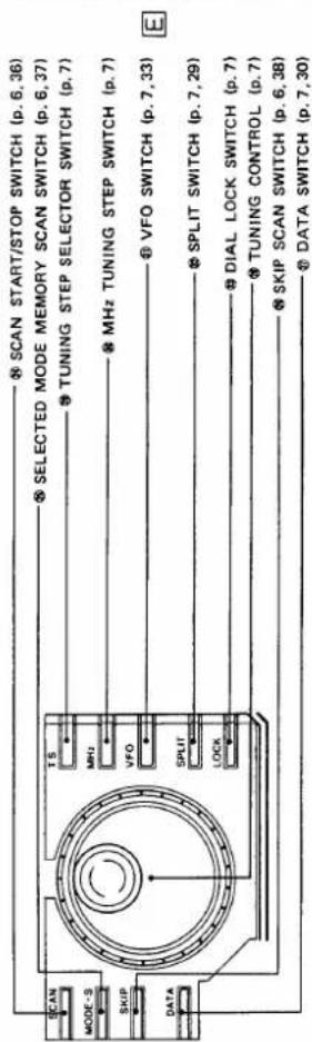
REAR PANEL
C
FOREWORD
Thank you very much for choosing this ICOM product.
The most sophisticated, 430MHz band all mode transceiver on the market today, the IC-475H is the result of both advanced ICOM engineering and state-of-art computer interface technology from ICOM such as the new CI-V System: a feature that allows for easy and convenient computer control of your IC-475H. The IC-475H delivers 75 full watts of high output power and is equipped with ICOM's pioneering new DDS (Direct Digital Synthesizer) System, an advanced, computer-developed innovation that enhances the PLL circuit in the IC-475H.
To fully understand and appreciate the uses of your new IC-475H, please study this instruction manual carefully prior to operation. Feel free to contact any authorized ICOM Dealer or Service Center if you have questions regarding the operation or capabilities of the IC-475H.
TABLE OF CONTENTS
1 PRECAUTIONS AND PREPARATIONS ..... 1
2 FEATURES 2
3 CONTROL FUNCTIONS 4
3-1 FRONT PANEL 4
3-2 FREQUENCY DISPLAY 9
3-3 REAR PANEL....11
4 INSTALLATION....13
4-1 PLANNING....13
4-2 MOUNTING THE TRANSCEIVER....13
4-3 ANTENNA 13
4-4 GROUNDING 13
5 INTERCONNECTIONS ..... 14
5-1 POWER SUPPLY 14
5-2 CONNECTING A LINEAR AMPLIFIER .....15
5-3 CONNECTING AN AFSK TERMINAL UNIT .....15
5-4 MIC CONNECTOR INFORMATION .....15
5-5 ACC(1) SOCKET INFORMATION .....16
5-6 AQS SOCKET INFORMATION....16
5 - 7 REMOTE CONTROL JACK (CI-V) INFORMATION .... 17
6 GENERAL OPERATION....18
6-1 INITIAL SETTINGS 18
6-2 FM OPERATION 18
6-3 SSB OPERATION 20
6-4 CW OPERATION 22
6-5 PACKET AND AMTOR OPERATIONS .....24
6-6 RTTY OPERATION 24
6-7 SSTV OPERATION 25
7 FUNCTIONS OPERATION 26
7 - 1 SPEECH COMPRESSOR OPERATION .....26
7-2 PREAMP SWITCH OPERATION 26
7-3 AGC OPERATION 27
7-4 NOISE BLANKER (NB) OPERATION .....27
7 - 5 SUBAUDIABLE TONE ENCODER AND 1750Hz TONE CALL OPERATIONS .....27
7-6 DUPLEX (SPLIT FREQUENCY) 28
7 - 7 DATA SWITCH OPERATION....30
7-8 PASSBAND TUNING OPERATION ....30
7-9 NOTCH FILTER OPERATION 30
7-10 RIT OPERATION 31
7-11 MICROPHONE UP/DOWN OPERATION .....32
7-12 SWR READING OPERATION 32
8 MEMORY AND SCANNING OPERATION ..... 33
8-1 VFO A AND B SELECTION....33
8-2 MEMORY CHANNEL AND VFO SELECTION ....33
8-3 MEMORY DATA TRANSFER 34
8-4 PROGRAMMING MEMORY CHANNELS.....34
8-5 PROGRAMMING THE CALL CHANNEL .....35
8-6 MEMORY CLEARING 35
8-7 SCANNING OPERATION 36
9 MAINTENANCE AND ADJUSTMENT 39
9-1 MAINTENANCE 39
9-2 ADJUSTMENT 40
10 INSIDE VIEWS 41
11 OPTION INSTALLATIONS 42
12 BLOCK DIAGRAM 44
13 SPECIFICATIONS 45
14 OPTIONS 46
15 SCHEMATIC DIAGRAM . . . . . . . . . . . . . . . . . . . . . . . . . . . . . . . . . . . . . . . . . . . . . . . . . . . . . . . . . . . . . . . . . . . . . . . . .
UNPACKING
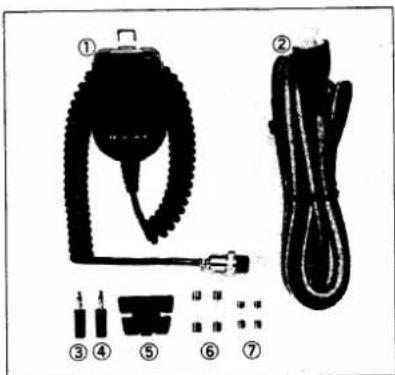
Accessories included with the IC-475H. Qty.
① Microphone (HM-12) 1
② DC Power Cable 1
③ External Speaker Plug .... 1
④ Key Plug 1
⑤ Microphone Hanger ..... 1
⑥ Spare Fuses (DC cable, 20A) ..... 2
⑦ Spare Fuses (PA unit, 3A) ..... 2
PRECAUTIONS AND PREPARATIONS
■ INSTALLATION LOCATIONS

- DO NOT place in excessively hot, humid, or dusty environments.
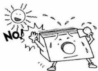
• DO NOT use in direct sunlight.

natural_image
Cartoon illustration of a character reacting to a TV screen with stars around (no text or symbols)- DO NOT place near radios or TV sets where unwanted noise or signals may be received.
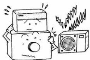
natural_image
Cartoon illustration of a distressed cheese maker reacting with a speaker emitting sound waves (no text or symbols)- DO NOT place an AC power supply on the transceiver or vice versa.
■ GROUNDING
To prevent electrical shocks, TVI, BCI and other problems, be sure to ground the transceiver through the GROUND TERMINAL. For best results, use the heaviest gauge wire or strap available and make the connection as short as possible.
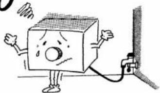
ONLY use a city water pipe as a good earth point if the pipe is well grounded and made of metal. NEVER use a gas pipe or electrical conduit pipe for grounding.
no
natural_image
Cartoon illustration of a sad cube character with arms and legs, standing next to a vertical pipe (no text or symbols)- NEVER use a gas pipe or electrical conduit pipe for grounding.
OK

natural_image
Cartoon illustration of a smiling cube character with musical notes and legs, standing on grass (no text or symbols)- USE the heaviest gauge wire or strap available and make the connection as short as possible.
OPERATING
TEMPERATURE NOTE
The IC-475H especially may become hot while transmitting for long periods of time.
210EETURES
■ ICOM'S NEWLY DEVELOPED STATE-OF-THE-ART FREQUENCY SYNTHESIZER
-5msec lockup time.
ICOM proudly announces its recent technological breakthrough in developing a new frequency synthesizer system: the ICOM DDS (Direct Digital Synthesizer) unit. Operating in just 5 milliseconds, this new system provides one of the fastest transceiver lockup times available on the market today, and is ideal for use with the popular PACKET and AMTOR communications systems. ICOM engineering has achieved this through the design of a sophisticated PLL UNIT which mixes, in split second time, DDS generated source frequencies in an advanced double phase-locked loop system.
■ NEWLY DEVELOPED ICOM CPU INSTALLED
●Built-in 99-channel large memory capacity.
Ninety-nine programmable memories are provided in the IC-475H to store frequency, mode, subaudible tone frequency, subaudible tone function ON/OFF, duplex direction, and offset frequency information. These memories are backed up by a lithium backup battery for up to five years.
●Advanced remote control system.
Full communications using a personal computer equipped with an RS-232C port are possible by using the serial port mounted on the rear panel of the IC-475H. The computer controls frequency, mode, VFO A/B selection, and memories when an appropriate interface is used. The serial port uses a standard 1200bps data transfer rate.
●Easy-to-read display.
An LCD (Liquid Crystal Display) in the IC-475H uses a soft orange illumination for easy visibility when operating on bright days. This display indicates the VFO in use, operating mode, memory channel, split mode, scan mode and other information.
●Scanning versatility.
The IC-475H incorporates a total of four separate scanning functions for easy access to a wide range of frequencies.
- MEMORY SCAN repeatedly scans the entire 99-channel memory in sequence.
- PROGRAMMED SCAN offers detailed coverage of a specific frequency range through repeated scanning.
- SELECTED MODE MEMORY SCAN automatically monitors all memories which contain programmed frequencies with a similar mode.
- SKIP SCAN allows you to continuously scan your favorite programmed memory channels.
■ OUTSTANDING RECEIVER PERFORMANCE
●PBT and NOTCH control.
ICOM's Passband Tuning and Notch Filter systems have been incorporated in the past as standard high class features in ICOM HF transceivers, but now these convenient features can also be enjoyed in a UHF transceiver: the IC-475H. Passband Tuning allows continuous center frequency adjustment of the IF passband, while the IF Notch Filter provides clear operating reception even in the presence of strong interference.
●High sensitivity, high dynamic range.
The IC-475H RF amplifier uses a low noise figure, high gain, disk-type GaAs-FET (3SK129) for UHF applications. Also, high sensitivity and a very high dynamic range are ensured since it uses a balanced-type mixer in the mixer stage. This mixer incorporates a UHF applicable transistor (2SC2026) with 2GHz frequency characteristics.
■ COMPLETE UHF TRANSCEIVER
- Compact size.
The IC-475H's compact size - only 241mm(9.5")(W) x 95mm (3.7")(H) x 239mm(9.4")(D) - simplifies installation in most mobile and portable situations: in automobiles, airplanes, boats or even in suitcases.
●PACKET, AMTOR operations.
The rear panel of the IC-475H has an easy-to-access terminal socket for AFSK (Audio Frequency Shift Keying) operation. Use the [DATA] SWITCH to rapidly switch between receive and transmit operations. This convenient function is made possible in the IC-475H by ICOM's exclusive new DDS (Direct Digital Synthesizer) System.
●Full break-in function.
For CW operators, both semi break-in and full break-in are provided for smooth, fast, and natural CW conversations.
■ OPERATIONS AVAILABLE
-UT-34 TONE SQUELCH UNIT
Provides you with interference-free communications.
- UT-36 VOICE SYNTHESIZER UNIT
Announces the displayed frequency.
- CT-16 SATELLITE INTERFACE UNIT
Satellite communication interface unit with the IC-275A/E/H.
- CT-17 CI-V LEVEL CONVERTER
Connect the IC-475H to a standard RS-232C I/O port.
●AG-35 WEATHERPROOF PREAMPLIFIER
430MHz preamplifier.
- FL-32A CW NARROW FILTER
500Hz at -6dB point.
●CR-64 HIGH-STABILITY CRYSTAL UNIT
0.5ppm (-30^ +60^)
S. CONTROL FUNCTIONS
3-1 FRONT PANEL
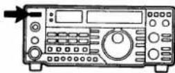
① POWER SWITCH [POWER]
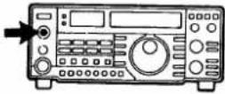
②AF GAIN CONTROL [AF]
③SQUELCH CONTROL [SQL]
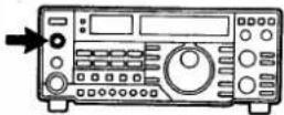
④PHONES JACK [PHONES]
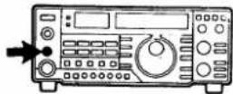
⑤MIC CONNECTOR [MIC] (p. 15)
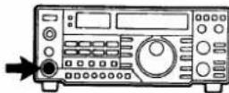
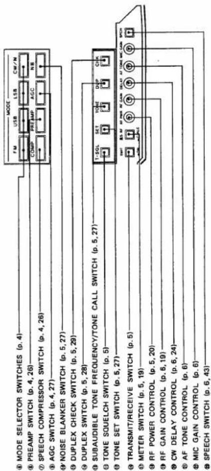
⑥MODE SELECTOR SWITCHES [FM] [USB] [LSB] [CW/N]
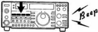
⑦SPEECH COMPRESSOR SWITCH [COMP] (p. 26)
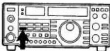
⑧ PREAMP SWITCH [PREAMP] (p. 26)
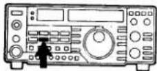
⑨ AUTOMATIC GAIN CONTROL SWITCH [AGC] (p. 27)
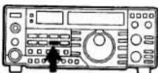
This is a push-lock switch which controls the input power to the IC-475H.
This control varies the audio output level. Clockwise rotation increases the level.
This control sets the squelch threshold level. To turn OFF the squelch function, rotate this control completely counterclockwise. To set the threshold level higher, rotate the control clockwise.
This jack accepts a standard 1/4 inch plug from headphones with an impedance of 4 \~ 16Ω. Stereo headphones may be used without modification.
Connect a suitable microphone to this connector. The supplied hand microphone or the optional microphones listed in SECTION 14 OPTIONS are ideal.
These switches select any of the four operating modes for the IC-475H: FM, USB, LSB, or CW. Push the appropriate switch for the desired mode.
This switch turns the built-in speech compressor circuit ON and OFF.
This switch turns the receiver preamplifier ON and OFF when the optional AG-35 preamplifier is connected.
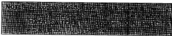
The [PREAMP] SWITCH does not function when the [DATA] SWITCH described in item ② is turned ON or the full break-in operation described in item ③ are selected.
This switch changes the time constant of the AGC circuit. When the switch is OUT, a SLOW time constant is selected. When the switch is IN, a FAST time constant is selected.
⑩NOISE BLANKER SWITCH [NB] (p. 27)
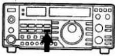
Push this switch IN to reduce pulse-type noise such as that generated by automobile ignition systems.
⑪ TONE SQUELCH SWITCH [T-SQL]
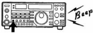
Push this switch to turn ON and OFF the Tone Squelch function alternately when the optional UT-34 TONE SQUELCH UNIT is installed.
⑫ TONE SET SWITCH [SET] (p. 27)
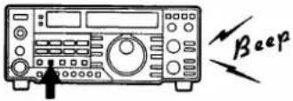
This switch is used with the [TONE] SWITCH described below in item ⑬ for setting the subaudible tone frequency of the tone encoder function.
⑬ SUBAUDIBLE TONE FREQUENCY/ TONE CALL SWITCH [TONE] (p. 27)
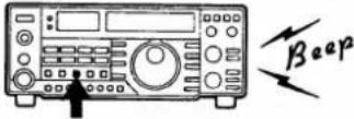
U.S.A., Australia versions
Push to activate the built-in subaudible tone circuit.
Europe, Sweden versions
Push to activate and transmit the 1750Hz tone call.
⑭ DUPLEX SWITCH [DUP] (p. 28)
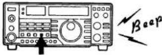
Push this switch to select simplex or duplex mode operation.
⑮ DUPLEX CHECK SWITCH [CHK] (p. 29)
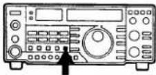
This switch allows the operator to monitor the transmit frequency when duplex mode is selected.
⑯ TRANSMIT/RECEIVE SWITCH [XMIT]
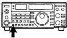
This switch is used to manually switch the transceiver from transmit to receive mode and vice versa.
IN position : Transmit
1 OUT position : Receive
⑰ METER SWITCH [S·RF] [C·ALC] (p. 19)
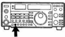
This switch selects the meter function and indicates the following:
| S·RF (OUT) | Signal strength | *Relative RF output power |
| C·ALC (IN) | FM : Frequency centerSSB,CW: Signal strength | ALC level |
* The [TX-METER] SWITCH on the rear panel should be in the [RF] position for indicating relative RF output power.
⑱ RF POWER CONTROL [RF PWR] (p. 20)
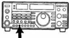
This control varies the RF output power from 10W to maximum continuously. Rotate clockwise to increase output power.
⑲ RF GAIN CONTROL [RF GAIN] (p. 19)
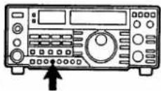
In SSB, CW modes:
This control varies the gain of the RF stage when the transceiver is in receive mode. Rotate clockwise for maximum gain.

In FM mode:
The control makes the variable attenuator function continuously from 0 to 20dB when the transceiver is in receive mode.
⑳ CW DELAY CONTROL [DELAY] (p. 24)
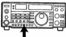
This control changes the transmit to receive switching time during CW semi break-in operation. Adjustment depends on the keying speed used. Clockwise rotation increases the delay time.
②1 AF TONE CONTROL [AF TONE]
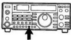
This control varies the receive audio tone. Adjust the control to receive the clearest, most pleasing audio tone.
② MIC GAIN CONTROL [MIC GAIN]
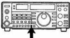
Adjust this control for a suitable modulation level while speaking into the microphone using your normal voice level. Rotate the control clockwise to increase the gain.
②3 SPEECH SWITCH [SPCH] (p. 43)
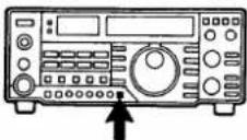
This switch activates the optional UT-36 VOICE SYNTHESIZER UNIT which announces the displayed frequency in English.
②4 SCAN START/STOP SWITCH [SCAN] (p. 36)
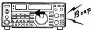
This switch starts and stops all the IC-475H scan functions.
②5 SELECTED MODE MEMORY SCAN SWITCH [MODE-S] (p. 37)
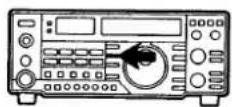
This switch turns ON and OFF the SELECTED MODE MEMORY SCAN function.
②6 SKIP SCAN SWITCH [SKIP] (p. 38)
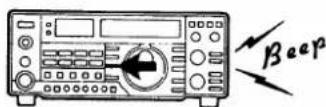
This switch is used for setting the skip channel to be skipped in MEMORY SCAN.
⑳ DATA SWITCH [DATA] (p. 30)
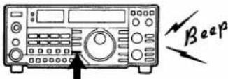
⑳ TUNING CONTROL
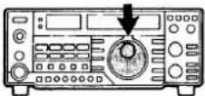
⑲ TUNING STEP SELECTOR SWITCH [TS]
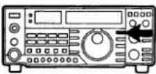
③0 MHz TUNING STEP SWITCH [MHz]
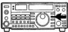
③1 VFO SWITCH [VFO] (p. 33)
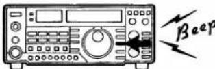
③2 SPLIT SWITCH [SPLIT] (p. 29)
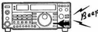
③3 DIAL LOCK SWITCH [LOCK]
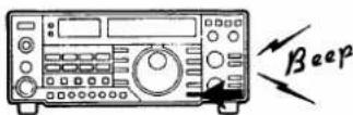
③4 CALL CHANNEL SWITCH [CALL] (p. 35)
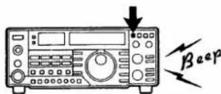
③5 FREQUENCY TRANSFER SWITCH [M▶ VFO] (p. 34)
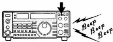
Push this switch to use operating modes such as PACKET or AMTOR communications which require rapid receive and transmit switching times.
Rotate this control clockwise to increase frequency numbers and counterclockwise to decrease them.
- Quick, continuous rotation of the TUNING CONTROL changes the frequency up or down by 10kHz. Slow rotation changes it by 2.5kHz, except when using FM mode.
Push this switch to increase the tuning step by 1kHz while operating in any mode. Push and release the switch again to return to the previous tuning step.
| POSITION | ITEM | USB/USB/GW |
| OUT | 5kHz | 10Hz |
| IN | 1kHz | 1kHz |
This switch sets the tuning step rate for 1MHz steps in any mode.
This switch selects VFO A or VFO B for tuning purposes. Each push of this switch selects one of the two VFOs alternately.
This switch also selects VFO A or VFO B mode from the MEMORY CHANNEL or CALL CHANNEL mode.
This switch selects the relationship of the two VFO frequencies. In the IN position, one VFO is for receive while the other VFO is for transmit. Each alternate push of this switch chooses the simplex and duplex modes.
This switch electronically locks the display frequency and deactivates the TUNING CONTROL. Push the switch IN and a beep sound is emitted, indicating that the function has been activated.
This switch selects the CALL CHANNEL which is most frequently used as a call frequency.
This switch operates differently depending on which mode the transceiver is in.
③6 VFO EQUALIZING SWITCH [A=B]
(p. 33)
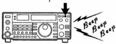
This switch instantly matches the frequency and mode of operation of the two VFOs.
- The display does not change when the [A=B] SWITCH is pushed. However, confirmation of the equalizing process is possible by pushing the [VFO] SWITCH which checks the frequency and mode of the opposite VFO.
③7 NOTCH FILTER SWITCH [NOTCH] (p. 30) This switch turns the NOTCH FILTER circuit ON and OFF.
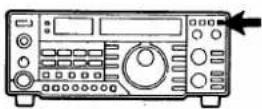
③8 NOTCH FILTER CONTROL [NOTCH] (p. 30)
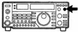
This control shifts the NOTCH FILTER frequency. Adjust the control to reduce or eliminate interfering signals.
⑲PASSBAND TUNING [PBT] (p. 30)
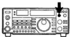
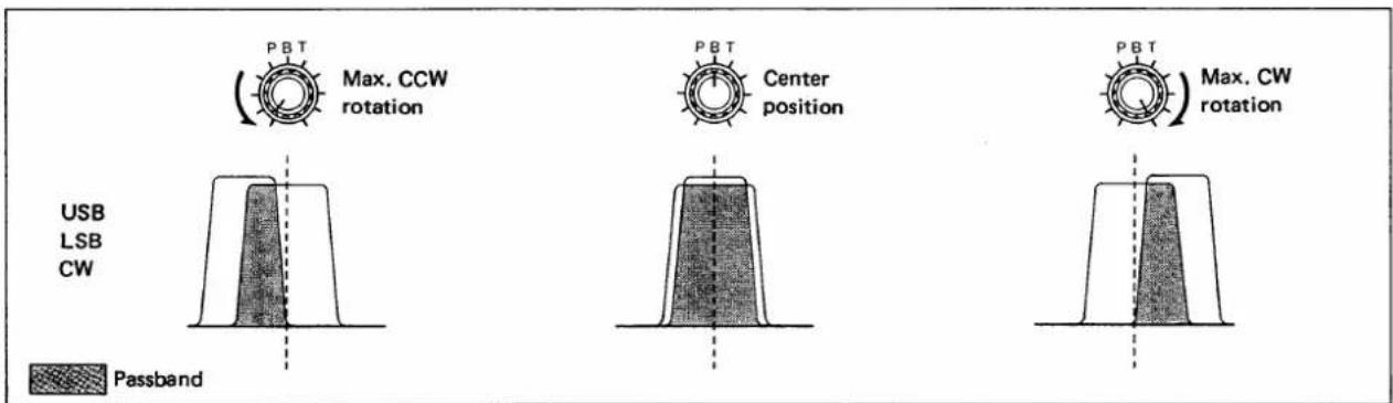
This control allows continuous tuning of passband selectivity by moving the filter center frequency to either side of the receive frequency in the SSB or CW mode.
④0 RIT SWITCH [RIT] (p. 31)
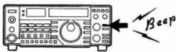
This switch turns the RIT circuit ON and OFF. The "RIT" INDICATOR appears on the FREQUENCY DISPLAY when the RIT function is activated.
④1 RIT CLEAR SWITCH [RIT-CL] (p. 31)
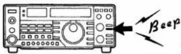
This switch clears the memory which contains the frequency shift information and resets the small incremental tuning display to "0.0".
④2 INCREMENTAL TUNING CONTROL
[- RIT +] (p. 31)
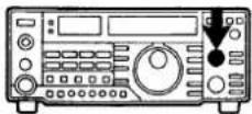
This control shifts the receive frequency by up to 9.99kHz to either side of the frequency indicated on the FREQUENCY DISPLAY.
④3 MEMORY READ SWITCH [MEMO] (p. 33)
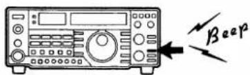
This switch selects the MEMORY CHANNEL mode. The "MEMO" INDICATOR appears on the FREQUENCY DISPLAY, and the "VFO A" or "VFO B" INDICATORS disappear.
④ MEMORY WRITE SWITCH [MW] (p. 34)
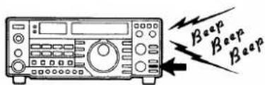
Push this switch to store displayed information in a memory channel.
④5 MEMORY CLEAR SWITCH [M-CL] (p. 35)
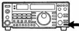
④6 MEMORY CHANNEL SELECTOR CONTROL [MEMO] (p. 33)
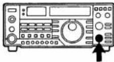
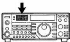
④7 FREQUENCY DISPLAY
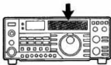
④8 METER
④9 TRANSMIT INDICATOR [XMIT]
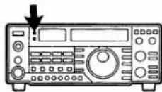
⑤⑥ RECEIVE INDICATOR [RECV]
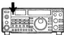
3-2 FREQUENCY DISPLAY
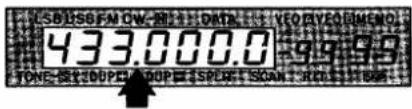
⑤1 FREQUENCY READOUT
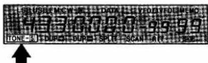
⑤2 TONE SQUELCH INDICATOR
This switch clears unwanted information in any memory channel. When pushed, information in the displayed memory channel is cleared and the memory channel reverts to blank status.
This control is used for selecting memory channels.
Refer to SECTION 3 - 2 FREQUENCY DISPLAY for more information.
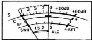
The meter functions as an S-meter or Center meter during receiving, and as an RF-meter or ALC-meter during transmitting. Refer to item ⑰ METER SWITCH.
This indicator lights up when the transceiver is in the transmit mode.
The indicator lights up when the transceiver is in the receive mode and the squelch opens.
This readout shows the operating frequency using a 7-digit display with 100Hz resolution.
"TONE-S" appears when the transceiver is activated using the Tone Squelch function with an optional UT-34 TONE SQUELCH UNIT.
"TONE" appears when the transceiver is acticated using the sub-audible tone function (U.S.A., Australia versions) or tone call function (Europe, Sweden versions).
⑤3 DUPLEX INDICATOR
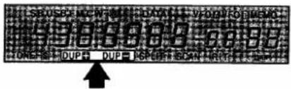
Either "DUP+" or "DUP—" appears when duplex mode is selected using the [DUP] SWITCH.
⑤4 SPLIT INDICATOR
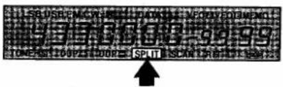
"SPLIT" appears when separate VFOs are used for the transmit and receive frequencies.
⑤5 SCAN INDICATOR
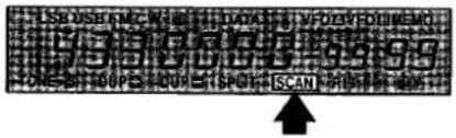
"SCAN" appears whenever a scan function is selected.
⑤6 RIT/SHIFT FREQUENCY INDICATOR
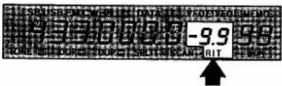
"RIT" and shift frequency appear when the RIT circuit is activated.
⑤7 SKIP CHANNEL INDICATOR
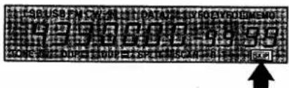
"SKIP" appears when the displayed memory channel is programmed for skip scan.
⑤8 MEMORY INDICATOR
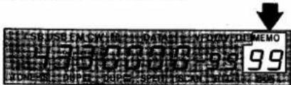
"MEMO" and selected memory channel numbers (1 \~ 99, P1, P2 and "C") appear when the MEMORY CHANNEL mode or CALL CHANNEL mode is selected.
⑤9 VFO INDICATOR
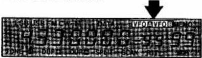
"VFO A" or "VFO B" appears, indicating which VFO is currently selected when operating in VFO mode.
⑥0 DATA INDICATOR
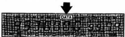
"DATA" appears when the [DATA] SWITCH is pushed.
⑥1 MODE INDICATOR
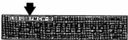
This area of the display shows the operating mode currently selected. The modes available are LSB, USB, FM, CW or CW-Narrow.
3-3 REAR PANEL
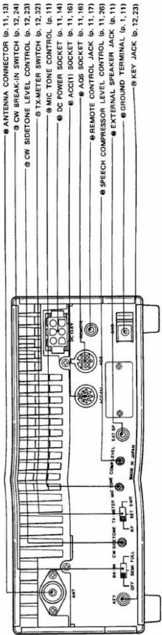
⑥2 DC POWER SOCKET [DC 13.8V] (p. 14)
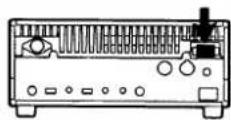
Connect the DC power cable from an external AC power supply or a 12V-type battery. Refer to SECTION 14 for information regarding optional AC power supplies available from ICOM.
⑥3 ANTENNA CONNECTOR [ANT] (p. 13)
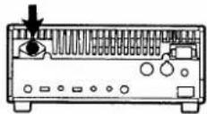
Connect a 50Ω impedance antenna to this connector. The connector should be matched with a Type-N connector.
⑥4 REMOTE CONTROL JACK [REMOTE] (p. 17)
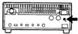
This is a communications port designed for use with a personal computer for remote operation of transceiver functions.
The new optional CT-17 CI-V LEVEL CONVERTER and CT-16 SATELLITE INTERFACE UNIT from ICOM can be used to connect the IC-475H using this jack.
⑥5 GROUND TERMINAL [GND] (p. 1)
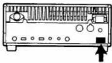
To prevent electrical shocks, TVI, BCI, and other problems, be sure to ground the transceiver through the GROUND TERMINAL.
⑥6 AQS SOCKET [AQS] (p. 16)
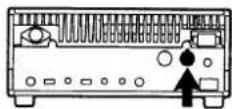
This socket provides signals for AQS (Amateur Quinmatic System).
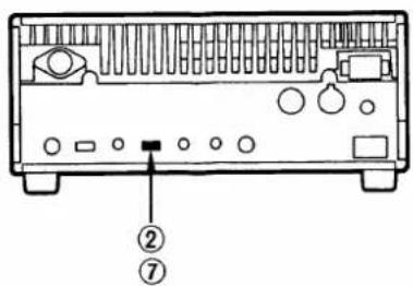
⑥7 ACC(1) SOCKET [ACC(1)] (p. 16)
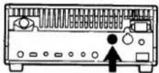
This socket provides signals such as T/R switching, receiver output, ALC input, etc.
⑥⁸ EXTERNAL SPEAKER JACK [EXT SP]
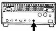
Connect an external speaker to this jack, if required. Use a speaker with an impedance of 4 \~ 16Ω. When using the EXTERNAL SPEAKER JACK, the built-in speaker does not function.
⑥9 SPEECH COMPRESSOR LEVEL CONTROL [COMP LEVEL] (p. 26)
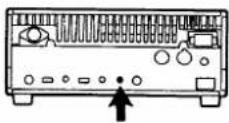
This control varies the compression level when the [COMP] SWITCH is pushed IN. The present circuit gain is approximately 10dB.
⑦ MIC TONE CONTROL [MIC TONE]
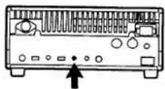
The bass and treble response of your transmitted signal may be altered with this control adjustment.
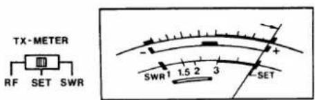
⑦1 TX-METER SWITCH [TX-METER] (p. 32)
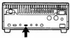
In the transmit mode, this switch selects one of three meter functions.
| POSITION | DESCRIPTION |
| The meter indicates the relative RF output power activated by the METER SWITCH on the front panel when it is set in the [S·RF] (OUT) position. | |
| Place the switch in the [SET] position to calibrate the front panel meter for measuring the SWR of the antenna system. Refer to SECTION 7 - 12 for measuring procedures. | |
| The front panel meter directly reads the antenna system SWR after calibration using the [SET] position. Refer to SECTION 7 - 12 for measuring procedures. | |
⑦ CW SIDETONE LEVEL CONTROL [CW SIDETONE] (p. 23)
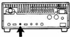
This control changes the audio level of the CW sidetone circuit. Adjust the control for the desired monitor volume.
⑦ CW BREAK-IN SWITCH [BK-IN] (p. 24)
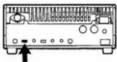
Place this switch in the [FULL] position for full break-in CW operation and in the [SEMI] position for semi break-in operation. Place this switch in the [OFF] position for non CW break-in operation.
⑦4 KEY JACK [KEY] (p. 23)
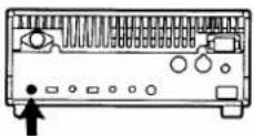
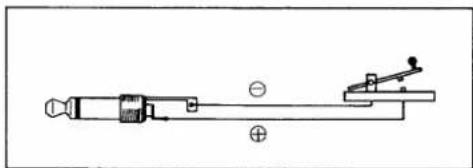
For CW operation, connect a CW key here using the supplied key plug.
4. INSTALLATION
4 - 1 PLANNING
Select a location for your transceiver which allows free access to the front panel controls, good air circulation and rear clearance for access to the rear panel connections.
4-2 MOUNTING THE TRANSCEIVER
Mobile installations:
An optional IC-MB5 MOBILE MOUNTING BRACKET is available for mobile installation of your IC-475H. Select a location which can support the weight of the transceiver, and which does not interfere with the normal operation of the vehicle.
4-3 ANTENNA
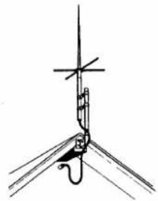
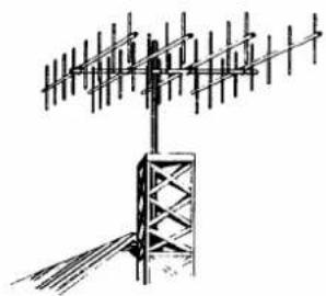
Antennas play a very important role in radio communications. If the antenna is inferior, your transceiver cannot deliver optimum performance. A well-matched 50Ω antenna and feedline will provide the desired effect. The transmission line should be a coaxial cable. The antenna system should show a VSWR of less than 1:1.5 when using a 50Ω coaxial transmission line.
• Ground plane antenna
natural_image
Pure mechanical diagram showing a lever and pivot point without any text, numbers, or symbols• Yagi beam antenna
natural_image
Line drawing of a multi-band antenna mounted on a tower, showing signal lines and antenna structure (no text or symbols)●TYPE-N CONNECTOR INSTALLATION
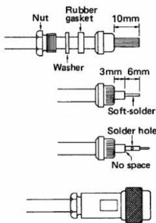
1) Slide the nut, washer, and rubber gasket over the coaxial cable and cut the end of the cable evenly.
2) Cut and remove 10mm of the outer vinyl jacket, and fold the braid back over the clamp. The clamp end should be flush with the end of the vinyl jacket. Evenly trim the braid ends.
3) Cut and remove 6mm of the shield conductor and the center conductor insulation.
4) Soft-solder the center conductor. Install a center conductor pin and solder it.
5) Carefully slide the plug body into place aligning the center conductor pin on the cable with the hold in the insulator inside the plug body.
6) Complete the assembly by screwing the nut into the plug body.
4 - 4 GROUNDING
Refer to SECTION 1 PRECAUTIONS AND PREPARATIONS for detailed grounding information.
5. INTERCONNECTIONS
5-1 POWER SUPPLY
To power the IC-475H from another external power supply or any other DC power source, be sure the output voltage is 12 \~ 15V and current capacity is at least 20A.
●Operation with the PS-55 AC POWER SUPPLY
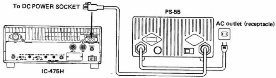
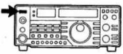
The [POWER] SWITCH synchronizes the PS-55 AC POWER SUPPLY with the IC-475H.
●Operation with non-ICOM AC power supplies
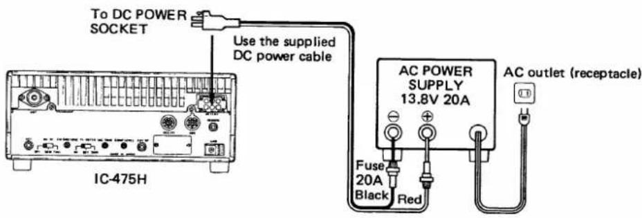
●Operation with a DC power source
Make the shortest possible direct connection to the battery using the supplied power cable.
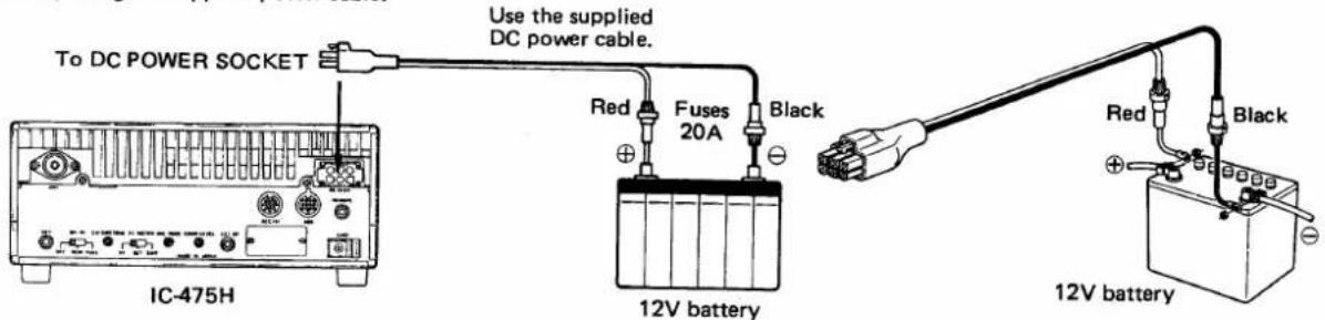
For safety purposes, remember to install fuses in the DC cable if connecting the IC-475H to a vehicle battery. Locate the fuses as close to the car battery as possible.
5-2 CONNECTING A LINEAR AMPLIFIER
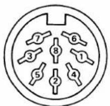
ACC(1)
The IC-475H is designed to operate into a load with a 50Ω impedance. Any amplifier used should have a 50Ω input impedance for best efficiency.
1) Pin 3 (SEND) is grounded when the transceiver is in transmit mode and opens when the transceiver returns to receive mode. The output condition of pin 3 controls either the transmit or receive function of the transceiver.
Specification for the keying rate is 20V DC maximum. DO NOT exceed this limit.
2) Pin 8 of the ACC(1) SOCKET is an ALC input for the Automatic Level Control signal from an external amplifier.
●Operation with an external linear amplifier
![IC-475H To [ANT] of IC-475H To IN of LINEAR AMPLIFIER ACC(1) Pin 8 ACC(1) Pin 3 ALC SEND IN Antenna connector OUT LINEAR AMPLIFIER](/content/2026/05/777925/images/e6ef8c01ae09d771e82c2539fe775dfb142872981638a118da00b4289756c91a.jpg)
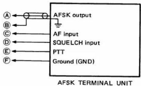
5-3 CONNECTING AN AFSK TERMINAL UNIT
When operating an AFSK such as RTTY, AMTOR or PACKET, connect the ACC(1) SOCKET as in the diagram below:
●Using the ACC(1) SOCKET
● Using the MIC CONNECTOR
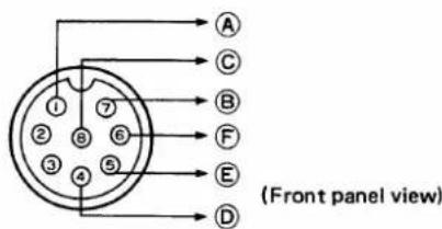
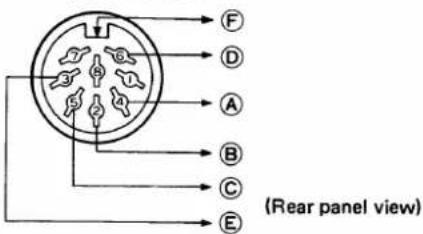
5-4 MIC CONNECTOR INFORMATION
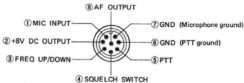
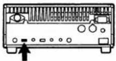
(Front panel view)
5 - 5 ACC (1) SOCKET INFORMATION
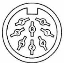
(Rear panel view)
Various signals are available from the ACC(1) SOCKET such as receiver output, modulator input, T/R changeover, etc.
| 1 | NC | No connection |
| 2 | GND | Ground |
| 3 | SEND | The transceiver switches to transmit mode when this terminal is grounded. It is grounded when the [XMIT] SWITCH is placed in the IN position. |
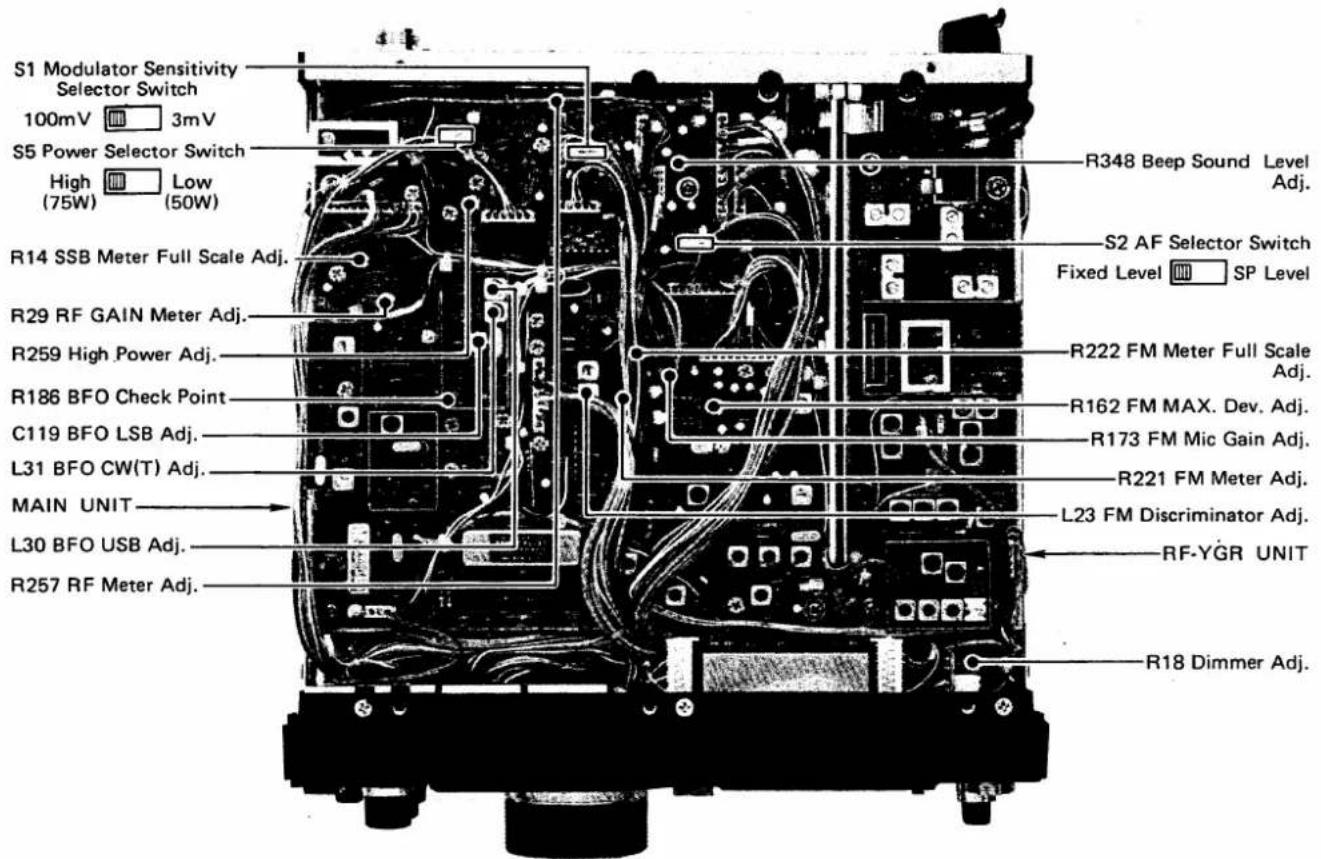
| 4 | MOD | Connected in the modulator stage. The modulator amplification level can be changed by using the S1 SWITCH. See page 41 for the location of this switch. |
| 5 | AF | Output from the receive detector stage. The output level can be changed by using the S2 SWITCH on the MAIN UNIT. See page 41 for the location of this switch. |
| 6 | SQLS | This terminal goes to ground level when the SQUELCH opens. |
| 7 | 13.8V | 13.8V DC output is switched by the [POWER] SWITCH on the front panel. Maximum current capacity is 1A. |
| 8 | ALC | Input for external ALC voltage. |
5-6 AQS SOCKET INFORMATION
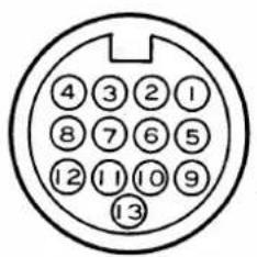
(Rear panel view)
| 1 | TX E | Modulator ground. |
| 2 | TX MOD | Modulator input. |
| 3 | MUTE | MUTE line for audio output and microphone input. The terminal is "LOW" while muting. |
| 4 | CAC | Valid signal output for CAC (Channel Access) function. The terminal is "HIGH" when the CAC function is activated. |
| 5 | RX AF | Output from the receive detector stage. |
| 6 | PTT | Connected to the PTT circuit. The terminal is "LOW" when transmitting. |
| 7 | SEND | This is an input terminal that the transceiver switches to in transmit mode when the terminal is "LOW". |
| 8 | SEARCH | When searching the empty channel, the terminal is "LOW". |
| 9 | E | Demodulator ground. |
| 10 | CI-V | This is the CPU I/O terminal for setting the frequency and mode. |
| 11 | NC | No connection |
| 12 | RECV | When receiving a signal, this terminal is "LOW" |
| 13 | 13.8 | This terminal outputs 13.8V DC. |
5-7 REMOTE CONTROL JACK (CI-V) INFORMATION
ICOM has introduced a new remote control Local Area Network, the ICOM COMMUNICATION INTERFACE-V (CI-V) SYSTEM using the CSMA (Carrier Sense Multiple Access with Collision Detection) standard.
- A serial data bus carries all control data. Operation is possible by installing a voltage level converter with a personal computer that has an RS-232C serial port.
The CT-17 CI-V LEVEL CONVERTER is available from ICOM for connecting your IC-475H to a personal computer. The CT-17 can be connected to a maximum of 4 transceivers.
- CT-17 connections
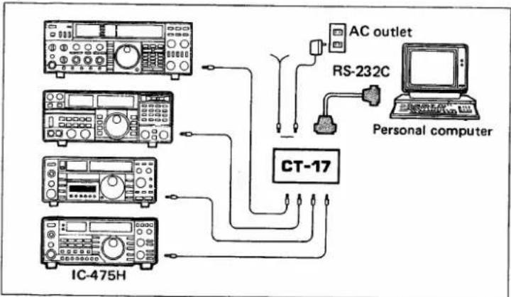
flowchart
graph TD
    A["AC outlet"] --> B["RS-232C"]
    B --> C["Personal computer"]
    D["CT-17"] --> E["IC-475H"]
    E --> F["Radio Station"]
    F --> G["Radio Line"]
    G --> H["Radio Signal"]
    I["Radio System"] --> J["Radio Station"]
    K["Radio System"] --> L["Radio Line"]
S3 SWITCHES (Switches 1 \~ 10)
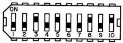
The S3 SWITCHES shown above are located on the LOGIC UNIT.
Transmitters and receivers using the ICOM CI-V System exchange serial information is the PACKET format. The contents of a data PACKET can be changed by using the S3 switches (Switches 1 to 10) on the LOGIC UNIT.
Switches 1 \~ 7 (for setting an address with your transceiver):
Switch 3 and Switch 5 in the ON position set an independent address for your IC-475H.
The ICOM standard address number for the IC-475H:
14H (decimals 20)
Switch 8 (For setting a transceive flag):
The ON position sets a flag used for sending or receiving code data of transceive operations automatically when the frequency is changed or code data are received. This switch must be OFF when the CT-16 SATELLITE INTERFACE UNIT is used.
Switches 9 and 10 (For setting CI-V baud rate):
| Band rate | Switch 9 | Switch 10 |
| 9600 | OFF | OFF |
| 4800 | ON | OFF |
| 1200 | OFF | ON |
| 300 | ON | ON |
NOTE:
The standard ICOM CI-V baud rate is 1200bps.
SATELLITE COMMUNICATIONS
Satellite communications are possible between the IC-475H and IC-275A/E/H by using an optional CT-16 SATELLITE INTERFACE UNIT.
The CT-16 provides easy tuning between two transceivers via an orbiting satellite.
When using the CT-16, set switches as follows:
• Transceive flag switch (Switch 8): ON
• Baud rate (Switch 9:OFF, Switch 10:ON): 1200bps
6 GENERAL OPERATION
6-1 INITIAL SETTINGS
After all INSTALLATION instructions have been followed in SECTION 4, including connecting an antenna system, set the controls and switches as indicated in the table below:
1) Check the DC output voltage if using a non-ICOM AC power supply.
2) An antenna must be connected to the ANTENNA CONNECTOR.

3) A ground connection must be made through the GROUND TERMINAL.
(1) Front panel switch and control settings
| 1 | POWER | OFF (Out) | 19 | RF GAIN | Max. CW |
| 2 | AF | Max. CCW | 20 | DELAY | Center |
| 3 | SQUELCH | Max. CCW | 21 | AF TONE | Center |
| 7 | COMP | OFF (Out) | 22 | MIC GAIN | Center |
| 8 | PREAMP | OFF (Out) | 29 | TS | OFF (Out) |
| 9 | AGC | Slow (Out) | 30 | MHz | OFF (Out) |
| 10 | NB | OFF (Out) | 33 | LOCK | OFF (Out) |
| 16 | XMIT | Receive (Out) | 37 | NOTCH SWITCH | OFF (Out) |
| 17 | S · RF/C · ALC | S · RF (Out) | 38 | NOTCH CONTROL | Center |
| 18 | RF PWR | Max. CCW | 39 | PBT | Center |
(2) Rear panel switch settings
| 65 | GND | Connect ground | 73 | BK-IN | OFF |
| 71 | TX-METER | RF |
6-2 FM OPERATION
(1) FM Receiving
1) Set the switches and controls.
1) Set the switches and controls as shown in section 6 - 1.
- The [PBT] CONTROL, [NOTCH] SWITCH and CONTROL, [NB] SWITCH, and [AGC] SWITCH do not function in this mode.
2) Turn power ON.
2) Push the [POWER] SWITCH IN to turn ON power.
• The FREQUENCY DISPLAY and METER light up.
3) Push [FM] SWITCH.
3) Push the [FM] MODE SWITCH to select FM mode.
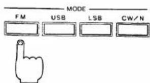
• The "FM" INDICATOR appears.
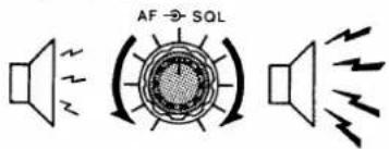
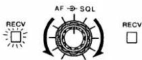
4) Adjust [AF] CONTROL.
5) Adjust [SQL] CONTROL.
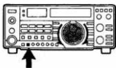
6) Select the METER SWITCH and turn the TUNING CONTROL.
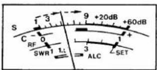
- S-meter
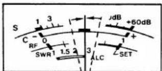
- Center meter
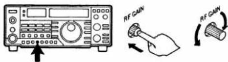
7) Adjust [RF GAIN] CONTROL.
• Tone Squelch operation
(2) FM transmitting
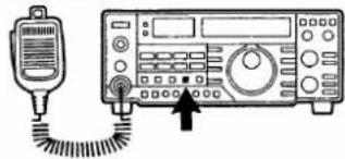
1) Switch to transmit mode.
![Push [PTT] SWITCH or Push [XMIT] SWITCH](/content/2026/05/777925/images/ac667db368fc22091b9677ec971c9bf89094a837cde45af30470e67c9c2781a8.jpg)
4) Turn the [AF] GAIN CONTROL to a suitable listening level.
5) Turn the [SQL] CONTROL clockwise until the noise is quieted.

6) Select the METER SWITCH and turn the TUNING CONTROL to receive an FM signal.
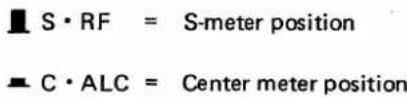
- When tuning an FM signal, tune for maximum signal strength as indicated on the meter in order to receive the clearest audio signal.
- The Center meter is useful for checking if the receive frequency is being received at maximum efficiency. Press the METER SWITCH IN to the [C.ALC] position to activate the Center meter.
7) The [RF GAIN] CONTROL functions as a variable attenuator in FM mode. Maximum counterclockwise rotation attenuates signals by 20dB.
This is a function created by an optional UT-34 TONE SQUELCH UNIT. It is designed for interference-free communications with other stations equipped with a similar system.
The following transmitting procedures should only be started after the steps in section 6 - 2 (1) FM receiving have been completed.
1) Select transmit mode with either the [XMIT] SWITCH on the front panel or [PTT] SWITCH on the microphone.
- The red TRANSMIT INDICATOR lights up whenever the IC-475H is placed in transmit mode.
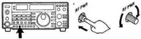
2) Adjust [RF PWR] CONTROL.
3) Speak into the mic.
![[MIC GAIN]](/content/2026/05/777925/images/8d41387b0893cbdb91f35cad0497d57354332f301e932770e8cd09faa1e5b451.jpg)
• FM REPEATER OPERATION
1) Push [DUP] SWITCH.
natural_image
Line drawing of a digital signal testing device connected to a probe with a probe inserted (no text or symbols visible)2) Switch to transmit.
![Push [PTT] SWITCH](/content/2026/05/777925/images/283144542c34d1c8d5c09fc7875783ccaee9ca251ceb202cb0f7459f0792481d.jpg)
2) Adjust the [RF PWR] CONTROL to obtain a suitable output power level.
3) Speak into the microphone using your normal voice level. Mic gain can be adjusted by using the [MIC GAIN] CONTROL.
- The meter needle indicates the relative carrier power when the METER SWITCH is in the OUT [S·RF] position. However, the needle does not move in time with your voice modulation in FM mode.
Following are the basic procedures for duplex operation. Refer to section 7 - 6 DUPLEX (SPLIT FREQUENCY) OPERATION (p.28) for further information.
1) Push the [DUP] SWITCH alternately to select the desired duplex direction.
$$ [ \mathrm{DUP} - ] \rightarrow [ \mathrm{DUP} + ] \rightarrow \text { No indication (SIMPLEX) } $$
2) Select the transmit mode.
- The receive frequency changes to the displayed transmit frequency. The degree of frequency change (offset frequency) can be programmed.
6-3 SSB OPERATION
(1) SSB receiving
1) Set the switches and controls.
2) Turn power ON.
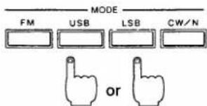
3) Push either [USB] or [LSB] SWITCH.
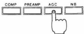
4) Push [AGC] SWITCH IN.
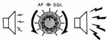
5) Adjust [AF] GAIN CONTROL.
1) Set the switches and controls as shown in section 6 - 1.
2) Push the [POWER] SWITCH IN to turn ON power.
• The FREQUENCY DISPLAY and METER light up.
3) Push either the [USB] or [LSB] SWITCH to select the desired mode.
- USB mode is commonly used in the 430MHz band.
- The "USB" or "LSB" INDICATORS appear.
4) Push the [AGC] SWITCH IN to select the AGC FAST position if the receive signals are fading rapidly.
5) Adjust the [AF] GAIN CONTROL to a suitable listening level.
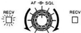
6) Turn [SQL] CONTROL.
7) Turn TUNING CONTROL
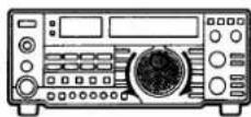
• NOISE BLANKER OPERATION
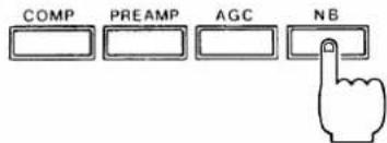
• PASSBAND TUNING OPERATION

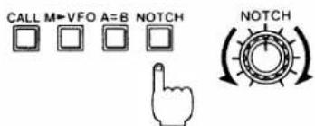
• NOTCH FILTER OPERATION
(2) SSB transmitting
1) Switch to transmit.
![Push [PTT] SWITCH or Push [XMIT] SWITCH](/content/2026/05/777925/images/4edb6a38f5198aeaa59f32021fe9c303e43cc8a095f0aacbb2ad5caf8d8b278e.jpg)
2) Set METER SWITCH to the ALC position.
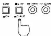
3) Adjust [MIC GAIN] CONTROL.

6) Turn the [SQL] CONTROL clockwise until the noise from the speaker is quieted.

7) Turn the TUNING CONTROL and search for a signal. Tune across the signal to its peak position to receive the clearest audio in the signal.
- The Passband Tuning, Notch Filter and Noise Blanker functions are very helpful in getting better readability when operating while receiving interference or pulse-type noise.
This is a useful function that reduces pulse-type noise such as that generated by automobile ignition systems. See page 27 for more detailed information.
This function reduces or eliminates interference. See page 30 for more detailed information.
This function can be used to reduce or eliminate interfering heterodyne signals that fall within the passband of the receiver. See page 30 for further information.
The following transmitting procedures should be followed only after completing the operation steps in 6 - 3 (1) SSB receiving.
1) Select transmit mode with either the [XMIT] SWITCH on the front panel or [PTT] SWITCH on the microphone.
- The red TRANSMIT INDICATOR lights up whenever the IC-475H placed in transmit mode.
2) Set the METER SWITCH to the ALC position. Speak into the microphone using your normal voice level.
3) Adjust the [MIC GAIN] CONTROL for a meter reading within the ALC zone on voice peaks.
4) Adjust [RF PWR] CONTROL.
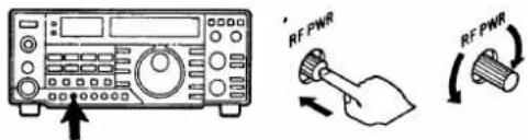
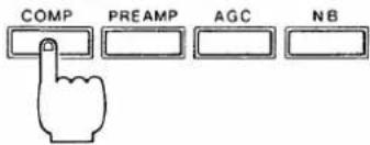
• SPEECH COMPRESSOR OPERATION
6-4 CW OPERATION
(1) CW receiving
1) Set the switches and controls.
2) Turn power ON.
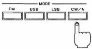
3) Push [CW/N] SWITCH.
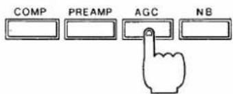
4) Push [AGC] SWITCH IN.
5) Adjust [AF] GAIN CONTROL.
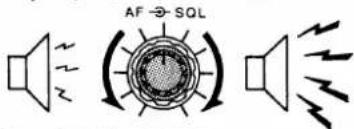
6) Turn [SQL] CONTROL.
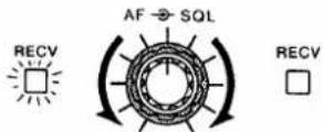
7) Turn TUNING CONTROL.
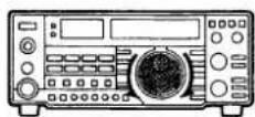
4) Adjust the [RF PWR] CONTROL to a suitable output power level.
The talk power can be increased over long distances by using this function. See page 26 for further information.
1) Set the switches and controls as shown in section 6 - 1.
2) Push the [POWER] SWITCH IN to turn ON power.
• The FREQUENCY DISPLAY and METER light up.
3) Push the [CW/N] MODE SWITCH once or twice to alternately select CW or CW-Narrow mode.
- The "CW" INDICATOR appears for a normal bandwidth.
- The "CW-N" INDICATOR appears for a narrow bandwidth, and is valid when the optional FL-32A CW NARROW FILTER is installed.

4) Push the [AGC] SWITCH IN to select the AGC FAST position.
5) Adjust the [AF] GAIN CONTROL to a suitable listening level.
6) Turn the [SQL] CONTROL clockwise until noise is quieted and the squelch closes.

7) Turn the TUNING CONTROL and search for a signal. Tune across the signal until the needle peaks while listening for the clearest audio signal.
- When receiving CW signals with an 800Hz tone, the receive and transmit frequencies of the station making contact are the same.
• NOISE BLANKER OPERATION
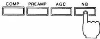
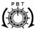
• PASSBAND TUNING OPERATION
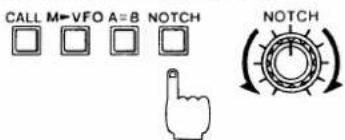
• NOTCH FILTER OPERATION
(2) CW transmitting
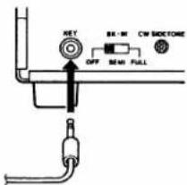
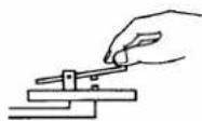
1) Connect CW key.
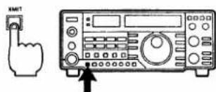
2) Select transmit mode.
3) Operate CW key.
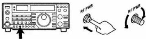
4) Adjust [RF PWR] CONTROL.
• CW SIDETONE MONITORING
This useful function reduces pulse-type noise such as that generated by automobile ignition systems. See page 27 for detailed information.
This function is designed to reduce or eliminate interference. See page 30 for detailed information.
This function may be used to reduce or eliminate interfering heterodyne signals that fall within the passband of the receiver. See page 30 for detailed information.
The following transmitting procedures should be started after first beginning the steps in section 6 - 4 (1) CW receiving.
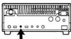
1) Insert the CW key plug into the KEY JACK on the rear panel.
natural_image
Pure electrical circuit lines without any symbols2) Select transmit mode with the [XMIT] SWITCH or [BK-IN] SWITCH on the rear panel. Refer to BREAK-IN OPERATION on page 24.
- The red TRANSMIT INDICATOR lights up whenever the IC-475H is placed in transmit mode.
3) Operate the CW key.
- The meter movement indicates that a signal is being transmitted.
- CW sidetone (described below) is emitted from the speaker.
4) Adjust the [RF PWR] CONTROL to obtain suitable output power.
An 800Hz sidetone oscillator is provided to monitor keying when operating in CW mode. This tone is also audible in receive mode and can be used for CW code practice or adjustment of the keyer.
- The [CW SIDETONE] CONTROL varies the volume of the oscillator tone. This control is located on the rear panel of the transceiver. The transceiver [AF] GAIN CONTROL also varies the volume.
• BREAK-IN OPERATION
BK-IN
OFF SEMI FULL

6-5 PACKET AND AMTOR OPERATIONS
The IC-475H has both semi break-in and full break-in capability. This means the transmit/receive switching is performed automatically by the transceiver whenever the keying starts or stops. The receive to transmit switching time is practically instantaneous, whereas the transmit to receive switching time may be varied through adjustment to suit an individual's keying speed.
1) Set the [BK-IN] SWITCH in either the semi break-in or full break-in position. This switch is located on the rear panel.
[SEMI] : Semi break-in operation [FULL] : Full break-in operation
2) Place the [XMIT] SWITCH in the receive position (OUT).
3) Begin sending with the CW key and the transceiver will switch between transmit and receive automatically.
4) Set the transmit release delay time to suit your keying speed by adjusting the [DELAY] CONTROL when operating with semi break-in.

PACKET and AMTOR operations require a rapid transmit and receive switching time since they are handshaking communications. The IC-475H requires only 5msec. for switching when the [DATA] SWITCH on the front panel is used.
1) Connect a terminal unit and any external equipment if required. See page 15 for proper interconnections.
2) Set the switches and controls as shown in section 6 - 1.
3) Turn power ON.
4) Set mode either to [FM], [USB], or [LSB]. CW mode is not acceptable for data communications.
5) Push the [DATA] SWITCH ON. The "DATA" INDICATOR appears.
6) Enter commands or data to operate your terminal unit with the IC-475H.
6-6 RTTY OPERATION
With the IC-475H, RTTY contacts may be enjoyed by using AFSK (Audio Frequency Shift Keying). The demodulator used should have 2125/2295Hz or 1700/2125Hz filters for 170Hz or 425Hz shift operation.
1) Connect a terminal unit and any external equipment if required. See page 15 for information regarding interconnections.
2) Set the switches and controls as shown in section 6 - 1.
3) Turn power ON.
4) Set the mode to [LSB].
5) Begin sending with your RTTY terminal unit.
- FREQUENCY READOUT
When operating in RTTY, there is a difference between the displayed frequency and the actual operating frequency.
Receiving:
Assuming the demodulator mark frequency is 2125Hz and the space frequency is 2295Hz:
$$ \binom{\text { Transmit frequency of }}{\text { contacted station }} = \text { Displayed frequency } - 2 1 2 5 \mathrm{Hz} $$
Transmitting:
Assuming the AFSK generator mark frequency is 2125Hz and the space frequency is 2295Hz:
$$ \binom{\text { Transmit frequency of }}{\text { your station }} = \text { Displayed frequency } - 2 1 2 5 \mathrm{Hz} $$
• USING AN AFSK GENERATOR
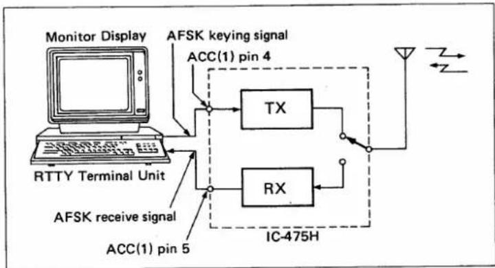
flowchart
graph TD
    A["Monitor Display"] --> B["RTTY Terminal Unit"]
    B --> C["AFSK keying signal ACC(1) pin 4"]
    C --> D["TX"]
    C --> E["RX"]
    D --> F["IC-475H"]
    E --> F
    F --> G["Antenna"]
    H["ACC(1) pin 5"] --> I["AFSK receive signal"]
- An RTTY Terminal Unit for AFSK operation can also be connected easily.
6-7 SSTV OPERATION
Slow Scan Television operation is also possible with the IC-475H.
- Connect the CAMERA OUTPUT on your SSTV unit to the ACC(1) CONNECTOR pin 4 or MIC CONNECTOR pin 1.
- The audio output signal is available from pin 5 on the ACC(1) SOCKET. The output level can be changed by S2 on the MAIN UNIT.
• See page 15 for ACC(1) SOCKET information.
7 FUNCTIONS OPERATION
7-1 SPEECH COMPRESSOR OPERATION
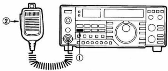
1) Set [COMP] SWITCH to ON position.
The IC-475H has a low distortion, AF speech compressor circuit which provides greater talk power by improving the intelligibility of the transmitted signal over long distances.
1) Set the switches and controls as shown in the table.
| MIC GAIN | Center (12 o'clock) |
| RF POWER | Max. CCW |
| COMP | ON (In) |
2) Switch to transmit mode and speak into the mic.
2) Switch to transmit mode and speak into the microphone using your normal voice level.
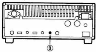
3) Adjust [COMP LEVEL] CONTROL if needed.
3) The compressor gain can be adjusted by the [COMP LEVEL] SPEECH COMPRESSOR LEVEL CONTROL on the rear panel.
- To increase the gain, rotate the [COMP LEVEL] clockwise.
7-2 PREAMP SWITCH OPERATION
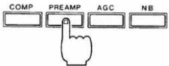
This switch is activated only when an optional AG-35 WEATHERPROOF 430MHz PREAMPLIFIER UNIT is installed. AG-35 improves S/N ratio and receiver sensitivity and makes DX-communication possible. The [PREAMP] SWITCH turns the receiver preamplifier ON and OFF.
1) Push [PREAMP] SWITCH.
flowchart
graph TD
    A["COMP"] --> B["PREAMP"]
    B --> C["AGC"]
    C --> D["NB"]
1) Push the [PREAMP] SWITCH.
- The preamp functions and amplifies signals.
2) Switch to transmit.
2) When transmitting, transmit signals will bypass the AG-35 preamp circuit automatically.
7-3 AGC OPERATION
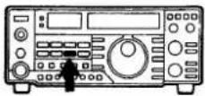
The IC-475H has a fast attack/slow release AGC system which maintains a peak voltage of a rectified IF signal from the IF amplifier circuit for a brief period of time.
This circuit prevents irritating background noise from being heard during the short pauses in speech. The damping effect of the AGC therefore allows accurate S-meter readings to be taken of peak IF signal strength.
1) For normal SSB reception:
Select the SLOW (OUT) position.
For CW reception or for SSB signals with short interval fading: Select the FAST (IN) position.
2) The AGC function does not work in FM mode.
7 - 4 NOISE BLANKER (NB) OPERATION
1) Push [NB] SWITCH.
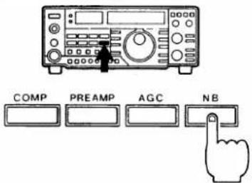
This operation effectively reduces unwanted pulse-type noise from outside sources such as ignition noise from vehicles.
1) Push the [NB] SWITCH.
2) The noise blanker may not work as well when strong signals are on nearby frequencies or when the noise is continuous rather than pulse-type.
7 - 5 SUBAUDIBLE TONE ENCODER AND 1750Hz TONE CALL OPERATIONS
Subaudible Tone Encoder (U.S.A., Australia versions)
The built-in tone encoder allows access to repeaters which require a subaudible tone superimposed on the transmit signal.
1750Hz Tone Call (Europe, Sweden versions)
An audible 1750Hz tone signal may be generated for the purpose of accessing repeaters.
The tone frequency can be programmed into each memory channel independently.
(1) Subaudible tone encoder operation
1) Select a memory channel you want to program the tone frequency in for the VFO modes or MEMORY CHANNEL mode.
2) Push the [TONE] SWITCH to turn ON the tone encoder function.
3) Push the [SET] SWITCH and rotate the TUNING CONTROL to select the desired tone frequency.
4) Push the [SET] SWITCH again to program the tone frequency. The [TONE] SWITCH alternately turns ON and OFF the tone encoder function.
(2) 1750Hz Tone Call operation
Push the [TONE] SWITCH to open the repeater and hold for approximately 1 \~ 3 seconds.
7-6 DUPLEX (SPLIT FREQUENCY) OPERATION
The purpose of the duplex function is to allow an operator the option of transmitting and receiving on two different frequencies.
The IC-475H provides duplex operation using either of the following two methods:
(1) Operating on user-programmed offset frequency.
(2) Operating on VFO A and VFO B with the [SPLIT] SWITCH.
(1) Programming the offset frequency
The offset frequency can be programmed for use in duplex operation.
Following is an example for programming the offset frequency at 7.6MHz.
1) Push [DUP] SWITCH.
2) Push [SET] SWITCH.
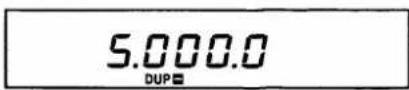
1) Push the [DUP] SWITCH to set the duplex mode.
2) Push the [SET] SWITCH. The subaudible tone function (U.S.A., Australia versions) must be turned OFF when resetting the offset frequency.
3) Rotate the TUNING CONTROL to "7.600.0" for the desired offset frequency of 7.6MHz.
4) Push one of the following switches to return to the normal operating mode: [TONE], [DUP] or [CHK].
3) Set the offset frequency for 7.6MHz.
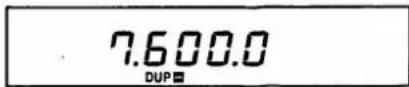
4) Return to normal operating mode.
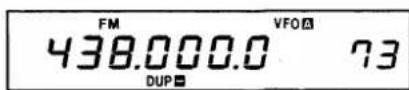
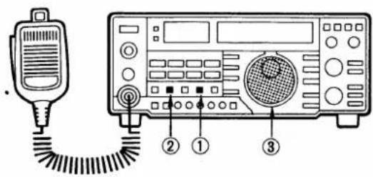
- Duplex operation using 7.6MHz offset frequency
Following are examples for duplex operation using 438.8000MHz for receiving and 431.2000MHz for transmitting with a 7.6MHz fixed offset frequency in FM mode.
1) Select 438.8000MHz and FM mode.
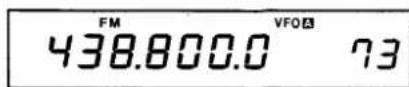
1) Select 438.8000MHz with the TUNING CONTROL and push the [FM] SWITCH.
2) Push [DUP] SWITCH to set the -DUPLEX mode.
2) Push the [DUP] SWITCH to set the -DUPLEX mode.
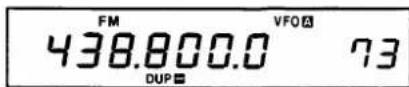
- "DUP—" appears on the FREQUENCY DISPLAY.
3) Transmit.
• Transmit frequency
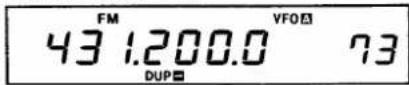
- Receive frequency
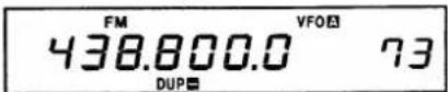
4) Push [CHK] SWITCH.
5) Push [DUP] SWITCH to cancel the duplex mode.
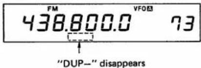
(2) Duplex operation using contents of VFO A and VFO B (SPLIT operation)
1) Set VFO A mode and program 439.9500MHz.
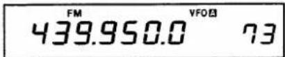
2) Set VFO B mode and program 431.0000MHz.
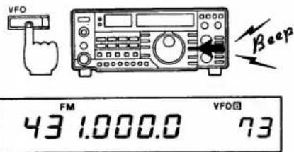
3) Return to VFO A mode.
4) Push [SPLIT] SWITCH.
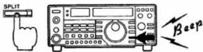
5) Transmit.
6) Receiving : 439.9500MHz
Transmitting : 431.0000MHz
3) Push either the [XMIT] or [PTT] SWITCH to transmit.
- The FREQUENCY DISPLAY should indicate 431.2000MHz for transmitting.
- You are now receiving on 438.8000MHz and transmitting on 431.2000MHz.
4) Push the [CHK] SWITCH to check the repeater input frequency, if needed.
5) Push the [DUP] SWITCH until either "DUP—" or "DUP+" disappear from the FREQUENCY DISPLAY, cancelling the duplex mode.
Duplex operation is possible using the contents of VFO A and VFO B.
Following is an example for 439.9500MHz for receiving and 431.0000MHz for transmitting on duplex (split frequency) operation.
1) Push the [VFO] SWITCH to set the transceiver in VFO A mode and set a receive frequency of 439.9500MHz with the TUNING CONTROL.
2) Push the [VFO] SWITCH to set the transceiver in VFO B mode and set a transmit frequency of 431.0000MHz with the TUNING CONTROL.
3) Push the [VFO] SWITCH again to return to VFO A mode.
4) Push the [SPLIT] SWITCH to enter the split frequency operation.
- "SPLIT" appears on the FREQUENCY DISPLAY.
5) Push either the [XMIT] or [PTT] SWITCH to transmit.
6) You are now receiving on 439.9500MHz and transmitting on 431.0000MHz. Push the [VFO] SWITCH once again to receive on 431.0000MHz and transmit on 439.9500MHz.
Each VFO also stores the operating mode in addition to the operating frequency. This allows crossmode contacts to be easily made.
7-7 DATA SWITCH OPERATION
This switch allows your to freely operate digital communications such as AMTOR or PACKET with time delay.
- The lockup time is approximately 5msec. when using the [DATA] SWITCH.
• The [DATA] SWITCH does not function in CW mode.
1) Connect the terminal unit to the IC-475H properly. See page 15 for detail.
![NOTE: Where the [DATA] SWITCH is ON once communications are not recommended, as the open close delay time of the squelch circuit is too short.](/content/2026/05/777925/images/16c5954091c9c58e35c3600172301742d6ab46f7ef21a806ca5939791b947150.jpg)
2) Select a mode switch and push the [DATA] SWITCH.
- "DATA" appears on the FREQUENCY DISPLAY.
7-8 PASSBAND TUNING (PBT) OPERATION
Passband Tuning is a system designed to electronically narrow the bandwidth (selectivity) of frequencies that will pass through the receive crystal filter.

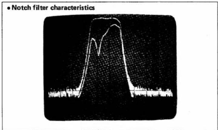
7-9 NOTCH FILTER OPERATION
This circuit provides high attenuation at one particular frequency in the IF passband. It may be used to reduce or eliminate interfering heterodyne signals that fall within the passband of the receiver.
1) Push [NOTCH] FILTER SWITCH.
1) Push the [NOTCH] FILTER SWITCH to the ON position (IN).
2) Adjust [NOTCH] FILTER CONTROL.
2) Adjust the [NOTCH] FILTER CONTROL to minimize interference.
7 - 10 RIT OPERATION
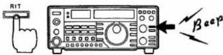
1) Push [RIT] SWITCH ON.
Receive : 433.6800MHz
Transmit : 433.6800MHz
![USB 433.680.0 VFO 0.0 73 [RIT] "RIT" appears →](/content/2026/05/777925/images/b3c913290c7414082824b6573e209f65dfbf658008fc1a9b1e02c04126e991b3.jpg)
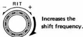
2) Rotate [RIT] CONTROL CW.
Receive : 433.6825MHz
Transmit : 433.6800MHz

3) To clear the RIT shift, push [RIT-CL] SWITCH.
Receive : 433.6800MHz
Transmit : 433.6800MHz
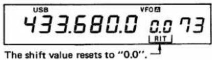
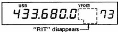
4) To turn OFF the RIT, push [RIT] SWITCH.
By using the RIT circuit, it is possible to shift the receive frequency up to 9.99kHz to either side of the transmit frequency without moving the transmit frequency. This is useful for fine tuning stations which transmit using off frequency or for compensating for frequency drift.
1) Push the [RIT] SWITCH to activate the RIT circuit.
- The letters "RIT" and the amount of shift are displayed.
- The shift frequency of the RIT changes in 10Hz steps even when the display changes in 100Hz steps.
2) Rotate the [RIT] INCREMENTAL TUNING CONTROL in the (+) direction to raise the receive frequency, and in the (−) direction to lower the frequency.
3) To clear the RIT shift frequency, push the [RIT-CL] SWITCH.
- The shift value resets to "0.0" and the receive and transmit frequencies become the same whether the RIT circuit is ON or OFF.
4) To turn OFF the RIT function, push the [RIT] SWITCH again.
- "RIT" and the amount of shift disappear from the FREQUENCY DISPLAY.
- The transmit and receive frequencies are the same as indicated on the FREQUENCY DISPLAY.
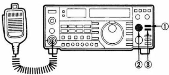
7 - 11 MICROPHONE UP/DOWN OPERATION
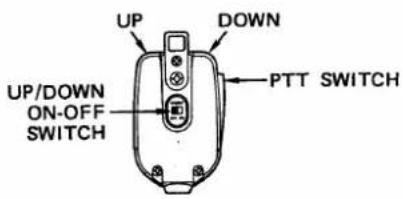
(1) Frequency control
(2) Memory channel selection
7-12 SWR READING OPERATION
This up/down function is useful for changing the operating frequency when using the VFO mode or when using the MEMORY CHANNEL mode.
Microphone UP/DOWN ON-OFF SWITCHES:
- OFF: The [UP] SWITCH and [DN] (down) SWITCHES on the microphone are disabled to eliminate the chance of accidental frequency or memory channel changes.
- ON: The [UP] or [DN] SWITCH can be used to change operating frequencies.
1) Each push of the [UP] or [DN] SWITCH on the supplied microphone changes the operating frequency one increment up or down, respectively.
2) Holding either switch down changes the operating frequency continuously in the same manner as the TUNING CONTROL.
1) When using the MEMORY CHANNEL mode, the memory channel may be changed with the microphone up/down switches.
2) The memory channel or the displayed memory channel number change continuously if the microphone switches are held down.
The IC-475H has a built-in SWR meter to check antenna matching as an aid to avoiding problems caused by high SWR.
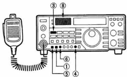
1) Set the METER SWITCH on the front panel to the [S-RF] position.
2) Set the [TX-METER] SWITCH on the rear panel to the [SET] position.
3) Select FM mode.
4) Rotate the [MIC GAIN] CONTROL fully CCW.
5) Push the [XMIT] SWITCH to the TRANSMIT (IN) position.
6) Adjust the [RF PWR] CONTROL located on the front panel to move the meter needle to "SET" on the SWR scale.
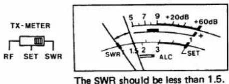
7) Set the [TX-METER] SWITCH to "SWR". Read the SWR from the SWR scale.
8) If the SWR is less than 1.5, the matching condition between the IC-475H and your antenna is good.
8 MEMORY AND SCANNING OPERATION
The IC-475H has ninety-nine memory channels. One frequency, the operating mode, the subaudible tone frequency, VFO A/B, and the duplex condition may be assigned to each memory channel whether the transceiver is in VFO mode or MEMORY CHANNEL mode.
8-1 VFO A AND B SELECTION
1) VFO A and VFO B can be selected by pushing the [VFO] SWITCH alternately.
2) The parameters in VFO A and VFO B can be made the same by pushing the [A = B] SWITCH.
Push [VFO]
![USB 433.000.0 VFO ←→ FM 438.700.0 VFO ↓ Push [A = B] USB 433.000.0 VFO ←→ Push [VFO] USB 433.000.0 VFO](/content/2026/05/777925/images/0b5e9c7b02cd680ee186090aafeb94dad892dea834397820a68bae19dc1f56a2.jpg)
8-2 MEMORY CHANNEL AND VFO SELECTION
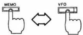
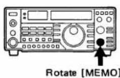
1) Push the [MEMO] SWITCH to select the MEMORY CHANNEL mode.
- "MEMO" appears on the FREQUENCY DISPLAY.
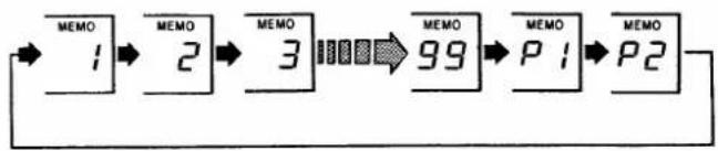
2) Rotate the [MEMO] CHANNEL SELECTOR CONTROL to select any of the memory channels.
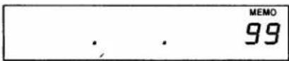
- When memory channels not yet programmed are selected, only decimal points appear on the FREQUENCY DISPLAY.
3) Push the [VFO] SWITCH to return to VFO A or VFO B mode selection.
Push [MEMO]

flowchart
graph LR
    A["1"] --> B["2"]
    B --> C["3"]
    C --> D["99"]
    D --> E["P1"]
    E --> F["P2"]
Push [VFO]

8-3 MEMORY DATA TRANSFER
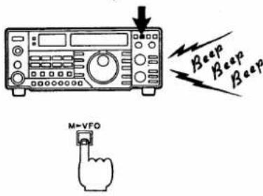
1) When the transceiver is in VFO mode, the frequency and modes stored in the memory channel displayed are transferred to the selected VFO.
2) When the transceiver is in MEMORY CHANNEL mode, the frequency and mode are transferred to the VFO used immediately before transferring to MEMORY CHANNEL mode.
1)
VFO mode
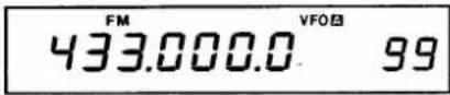
Push [M▶VFO]

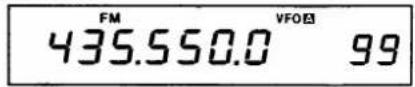
2)
MEMORY CHANNEL mode
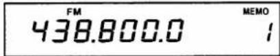
Push [M▶VFO]
and [VFO]

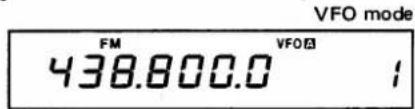
8-4 PROGRAMMING MEMORY CHANNELS
1) Select operating parameters.
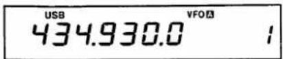
Any frequency, operating mode, subaudible tone frequency, VFO A/B, or duplex condition may be memorized in any memory channel.
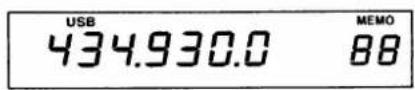
Following are instructions for programming 434.9300MHz and USB mode into Memory Channel 88.
2) Select Memory Channel 88.
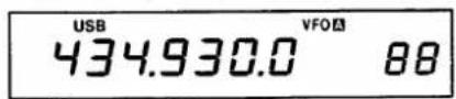
1) Set the frequency and mode for 434.9300MHz and USB using the TUNING CONTROL and [USB] MODE SWITCH respectively. VFO A or B may be used while selecting these parameters.
2) Select Memory Channel 88 by rotating the [MEMO] CHANNEL SELECTOR CONTROL.
3) Push [MW] SWITCH.
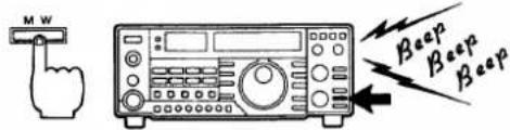
3) Push the [MW] SWITCH to program these parameters into Memory Channel 88.
- If the programming is successful, three short beep tones will be emitted.
4) Push [MEMO] SWITCH to check contents.
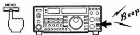
4) To check the memory channel contents, push the [MEMO] SWITCH.
- The contents of the selected memory channel are displayed.
8-5 PROGRAMMING THE CALL CHANNEL
(1) Programming the CALL CHANNEL
1) Hold down [CALL] SWITCH and set the call frequency.
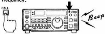
2) Set the parameters.
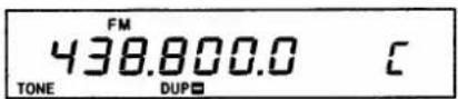
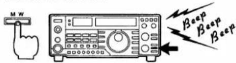
3) Push [MW] SWITCH.
(2) Recalling CALL CHANNEL information
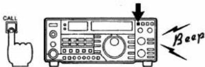
1) Push [CALL] SWITCH.
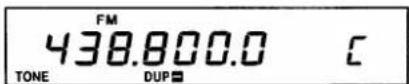
2) The "C" and call frequency appear.
3) Push either [VFO] or [MEMO] SWITCH to return to VFO or MEMORY CHANNEL mode.
8-6 MEMORY CLEARING
1) Push [MEMO] SWITCH.
2) Select the memory channel to be cleared.
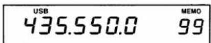
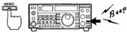
3) Push [M-CL] SWITCH.
This CALL CHANNEL is useful for quickly recalling and changing frequently used frequencies from any operating mode.
1) Hold down the [CALL] SWITCH and set the desired call frequency by rotating the TUNING CONTROL, then release the [CALL] SWITCH.
2) Set the needed parameters such as operating mode, subaudible tone frequency, and duplex condition using each switch.
3) Push the [MW] SWITCH until three beep tones are emitted for storing these parameters.
CALL CHANNEL information can be recalled.
1) Push the [CALL] SWITCH.
2) "C" and the programmed call frequency appear on the FREQUENCY DISPLAY.
3) Push either the [VFO] or [MEMO] SWITCH to return to VFO or the MEMORY CHANNEL mode.
This function is used to clear the information in each memory channel.
1) Push the [MEMO] SWITCH to enter MEMORY CHANNEL mode.
2) Select the memory channel to be cleared by rotating the [MEMO] CHANNEL SELECTOR CONTROL.
3) Push the [M-CL] SWITCH until three beep tones are emitted from the speaker.
• The memory channel is now vacant.
8-7 SCANNING OPERATION
The IC-475H comes equipped with four scan functions, providing tremendous scanning versatility at the touch of just a few switches.
| SCAN TYPE | HUAANILIPOPERATION |
| MEMORY CHANNEL SCAN | Scans all MEMORY CHANNELS containing information while skipping memories in blank status. |
| PROGRAMMED SCAN | Repeatedly scans between two user-PROGRAMMED frequencies in the scan range using independent memories P1 and P2 for storage of frequency data. |
| SELECTED MODE MEMORY SCAN | Repeatedly scans all memory channels containing frequencies in the same MODE as the displayed frequency. |
| SKIP SCAN | Scans all specified memory channels while skipping unspecified channels and those in blank status. |
- Scan function notes
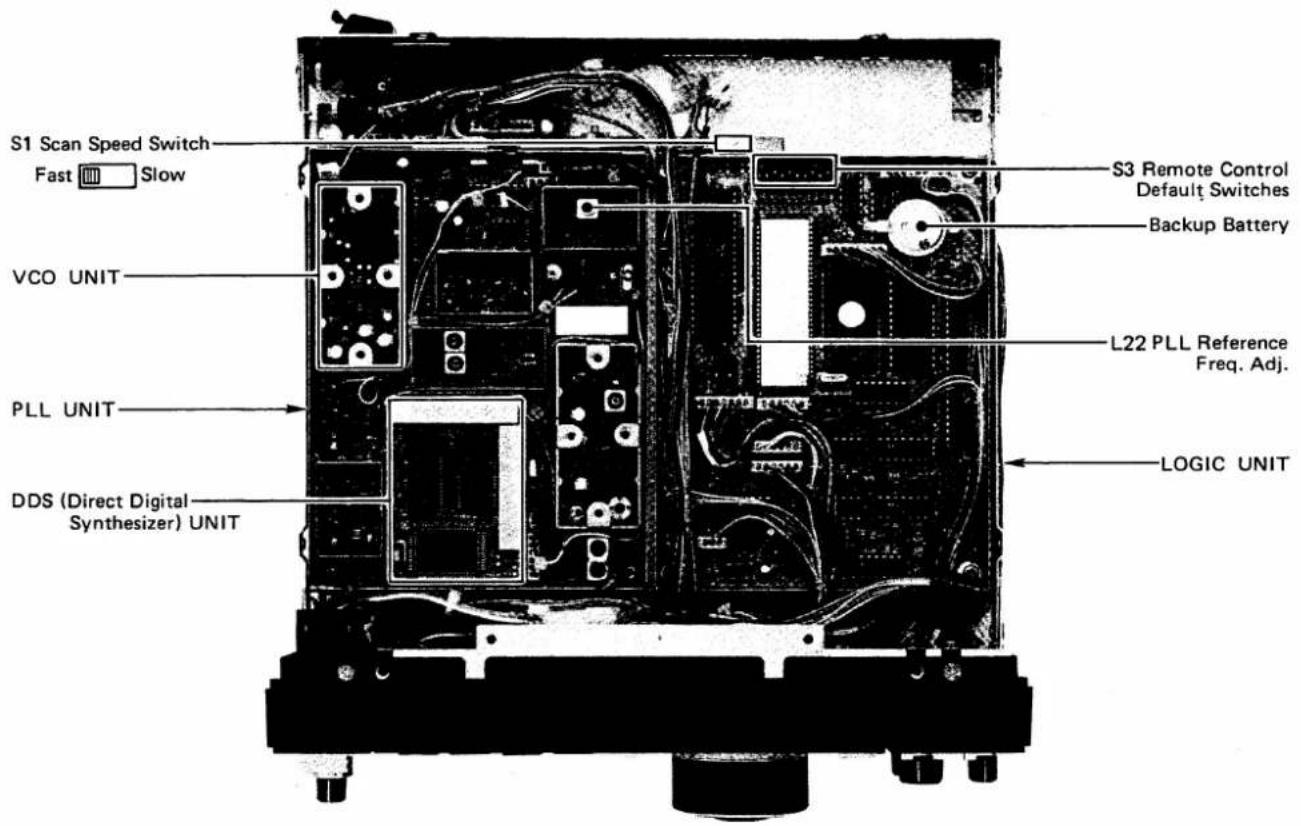
Before starting scanning operations, please read the following additional information and preset the switches and controls. See section 10 INSIDE VIEWS (p. 41) for switch locations.
① SCAN SPEED SWITCH
Switches the scan speed in any scan mode. Slide the switch to the position for the desired speed. The switch is located on the PLL UNIT and is factory set for the fast position.
②ADJUSTING SQUELCH CONTROL
Adjust the [SQL] CONTROL to quiet the noise output from the speaker since the scan will stop only if the squelch is set.
③SCAN TIMER
When a signal is received, the scan stops and then starts again after 3 or 10 seconds. These times depend on the type of signal received.
3 seconds : A signal of short duration such as pulse signals. 10 seconds : A signal of long duration such as voice signals.
(1) Memory scan
This function is used to automatically scan all programmed memory channels.
1) Program memory channels.
1) Program the desired frequencies into memory channels. See page 34 PROGRAMMING MEMORY CHANNELS.
2) Adjust [SQL] CONTROL.
2) Adjust the [SQL] CONTROL to quiet the noise output from the speaker.
3) Push [MEMO] SWITCH.
3) Push the [MEMO] SWITCH to select MEMORY CHANNEL mode.
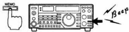
4) Push [SCAN] SWITCH.
4) Push the [SCAN] SWITCH to start the scan.
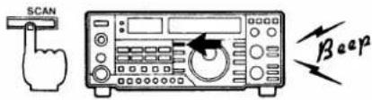
- "SCAN" appears on the FREQUENCY DISPLAY.
- The IC-475H begins scanning the programmed channels from the lowest channel towards the highest channel.
5) The scan stops when a receive signal opens squelch.
5) The scan stops for approximately 3 or 10 seconds after a receive signal opens the squelch, then resumes scanning.
6) Use [SCAN] SWITCH to manually stop the scan.
6) Push the [SCAN] SWITCH to stop the scan function manually. Turning the TUNING CONTROL also stops the scan.
- "SCAN" disappears.
(2) Programmed scan
The purpose of this scanning function is to monitor a particular section of the band.
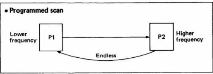
flowchart
graph LR
    P1["Lower frequency"] --> P2["Higher frequency"]
    P2 -->|Endless| P1
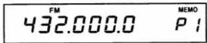
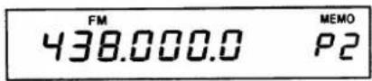
1) Store the scan limits in Memory Channels P1 and P2.
2) Select the desired mode.
3) Adjust [SQL] CONTROL.
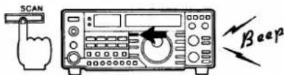
4) Push [SCAN] SWITCH to start scan.
5) The squelch opens when a signal is received.
6) Push [SCAN] SWITCH to cancel scanning manually.
(3) Selected mode memory scan
1) Store desired frequencies.
2) Push [MEMO] SWITCH.
3) Adjust [SQL] CONTROL.
4) Push one of the four MODE SWITCHES.
1) Store the frequencies of the HIGH and LOW limits of the desired scanning range in memory channels P1 and P2.
- Turn the [MEMO] SELECTOR CONTROL to select Memory Channels P1 and P2. See page 34 PROGRAMMING MEMORY CHANNELS.
- The scan begins from the LOW limit of the range regardless of which channel has the lower frequency stored.
2) Select the desired mode.
3) Adjust the [SQL] CONTROL to quiet the noise output from the speaker.
4) Push the [SCAN] SWITCH to start the scan. The scanning rate depends on the [TS] SWITCH position.
- "SCAN" appears on the FREQUENCY DISPLAY.
5) The squelch opens when a signal is received. After approximately 3 or 10 seconds the scan resumes scanning.
6) Push the [SCAN] SWITCH while the scan is operating or during the 3 or 10 second delay period to manually cancel the scan.
- Transmitting or rotating the TUNING CONTROL also cancels the scanning function.
The purpose of this scan is to selectively monitor memory channels which contain frequencies programmed with the same mode: FM, USB, LSB or CW.
1) Store the desired frequencies with mode into memory channels.
2) Push the [MEMO] SWITCH to select MEMORY CHANNEL mode.
3) Adjust the [SQL]CONTROL to quiet the noise output from the speaker.
4) Push one of the four MODE SWITCHES to select a receive mode.
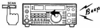
5) Push [MODE-S] SWITCH.
6) Push [SCAN] SWITCH.
7) The squelch opens when a signal is received.
8) Push [SCAN] SWITCH to manually stop the scan.
(4) Skip scan
1) Store desired frequencies.
2) Push [MEMO] SWITCH.
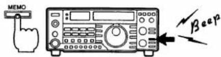
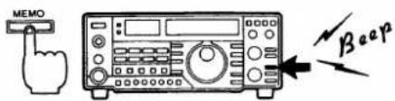
3) Select MEMORY CHANNELS you do not want to receive in.
4) Push [SKIP] SWITCH.
5) Adjust [SQL] CONTROL.
6) Push [SCAN] SWITCH.
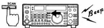
7) The squelch opens when a signal is received.
8) Use [SCAN] SWITCH to manually stop the scan.
5) Push the [MODE-S] SWITCH to set the SELECTED MODE MEMORY SCAN.
6) Push the [SCAN] SWITCH to start the scan.
- "SCAN" appears on the FREQUENCY DISPLAY.
- If a longer beep tone is emitted, no frequency with the desired mode is stored in the memory channels.
7) The squelch opens when a signal is received. After approximately 3 or 10 seconds the scan resumes.
8) Push the [SCAN] SWITCH to stop the scanning function manually. Turning the TUNING CONTROL also stops the scan.
SKIP SCAN repeatedly scans specific memory channels chosen by the user.
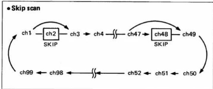
flowchart
graph TD
    A["ch1"] --> B["ch2"]
    B --> C["SKIP"]
    C --> D["ch3"]
    D --> E["ch4"]
    E --> F["..."]
    F --> G["ch47"]
    G --> H["ch48"]
    H --> I["SKIP"]
    I --> J["ch49"]
    J --> K["ch50"]
    K --> L["ch51"]
    L --> M["ch52"]
    M --> N["..."]
    N --> O["ch98"]
    O --> P["ch99"]
    P --> Q["..."]
    Q --> R["..."]
    R --> S["..."]
    S --> T["..."]
    T --> U["..."]
    U --> V["..."]
    V --> W["..."]
    W --> X["..."]
    X --> Y["..."]
    Y --> Z["..."]
    Z --> A
1) Store the desired frequencies with mode, etc., into a memory channel.
2) Push [MEMO] SWITCH to select the MEMORY CHANNEL mode.
3) Select MEMORY CHANNELS you do not want to receive in during scanning operations by using the [MEMO] SELECTOR CONTROL.
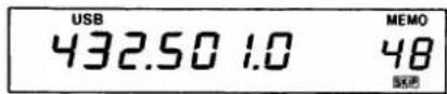
4) Push the [SKIP] SWITCH to program a frequency to be skipped into the memory channel.
- "SKIP" appears on the FREQUENCY DISPLAY.
5) Adjust the [SQL] CONTROL to quiet the noise output from the speaker.
6) Push the [SCAN] SWITCH to start the scan.
- "SCAN" appears on the FREQUENCY DISPLAY.
7) The squelch opens when a signal is received. After approximately 3 or 10 seconds the scan resumes.
8) Push the [SCAN] SWITCH to stop the scanning function manually. Turning the TUNING CONTROL also stops the scan.
S MAINTENANCE AND ADJUSTMENT
9 - 1 MAINTENANCE
(1) Cleaning
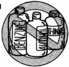
If the transceiver becomes dusty or dirty, wipe it clean with a dry, soft cloth. Avoid the use of strong cleaning agents such as benzine or alcohol as they may damage the surfaces.
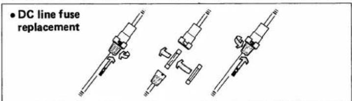
(2) Fuse replacement
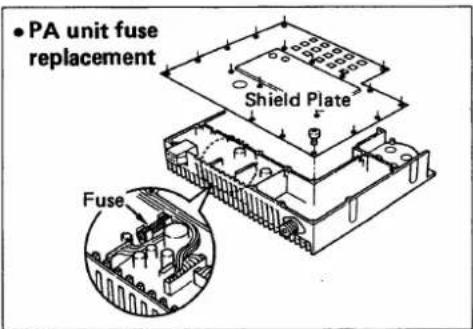
If the fuse blows or the transceiver stops functioning, track down the source of the problem if possible, and replace the damaged fuse with a new, rated fuse.
PA unit fuse F.G.M.B. 125V 3A DC cable 20A
(3) Backup Battery
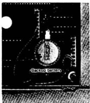
The IC-475H uses an advanced, highly reliable microprocessor chip. The purpose of the battery is to provide power to the microprocessor so it retains all memory information during power failures, or when the unit is unplugged or turned OFF.
- The usual life of the backup battery exceeds five years. It is advisable to monitor the battery carefully and replace it if there are repeated cases of display malfunction.
- The transceiver transmits and receives normally if the backup battery is exhausted but the transceiver cannot memorize frequencies.
(4) Resetting the internal microprocessor
NOTE: Bargeplacement should be gone by unauthorized IT COM Dealer or COM Service Center
Occasionally, the FREQUENCY DISPLAY may display erroneous information either during operation or when first applying power. This may, for example, be due to an external cause such as static electricity.
When this sort of problem is encountered, turn OFF the power to the IC-475H, wait for a few seconds and turn ON the power again. If the problem persists, perform the following procedure.
NOTE: A large number program management channels will be tested in the scenarios recently.
1) Turn power OFF, hold down the [M-CL] SWITCH, and turn power ON.
2) The IC-475H is now reset.
A built-in protector circuit automatically holds transmit output power at half of maximum power when operating the transceiver continuously at maximum power. This protects the final transistors from overheating.
(5) Automatic protector circuit
9 - 2 ADJUSTMENTS
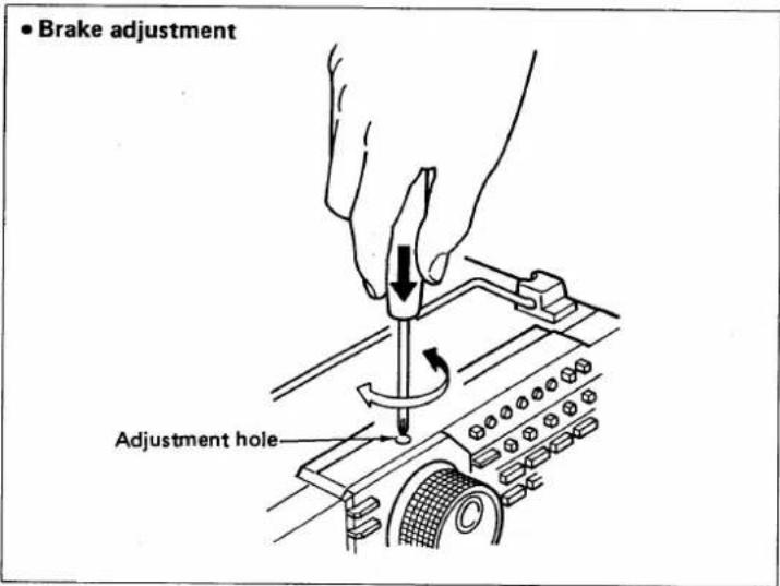
(1) Brake adjustment
The TUNING CONTROL tension may be adjusted to the operator's preference. The screw adjustment is located on the bottom side of the transceiver cabinet below the TUNING CONTROL. The method for adjustment is as follows:
1) Rotate the TUNING CONTROL continuously and smoothly in one direction.
2) Adjust the brake adjustment screw either CW for tighter tension, or CCW for looser tension as desired.
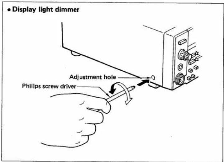
(2) Display light dimmer adjustment
The IC-475H has an illuminated FREQUENCY DISPLAY for easy reading in dim or no light situations. The light intensity may be varied to suit the ambient light conditions.
(3) Beep sound level adjustment
The level of the beep sound which is emitted when the specified switches are pushed can be adjusted by R348 on the MAIN UNIT.
- CCW rotation of R348 increases the sound level.
• See section 10 INSIDE VIEWS for the location of R348.
OINSIDE VIEWS
■ MAIN AND RF-YGR UNITS
■ PLL AND LOGIC UNITS
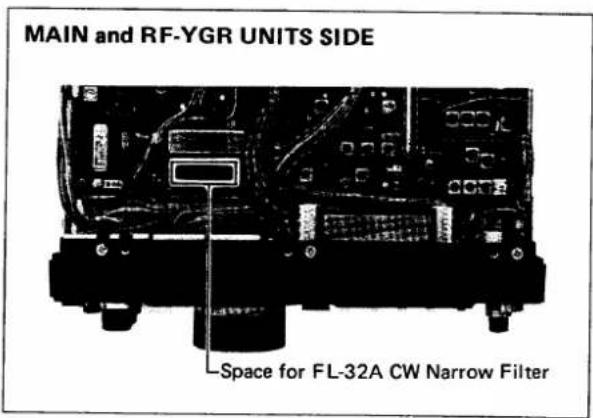
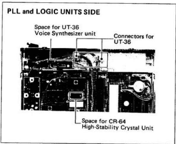
THE OPTION INSTALLATIONS
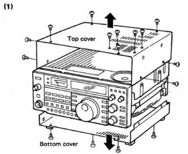
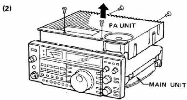
■ TRANSCEIVER DISASSEMBLY
1) Remove the top and bottom covers. The PA UNIT is located beneath the top cover.
2) Remove the PA UNIT. The MAIN and RF-YGR UNITS are located beneath the bottom cover.
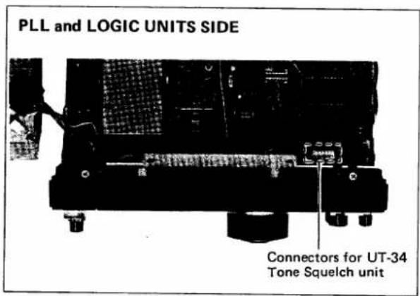
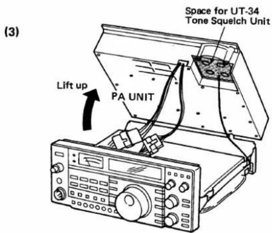
3) The PLL and LOGIC UNITS are located underneath the PA UNIT.
■ UT-34
TONE SQUELCH UNIT
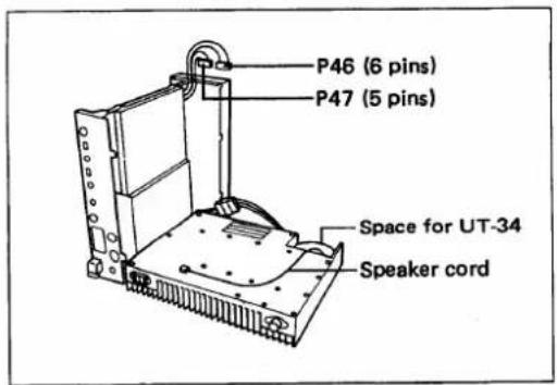
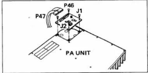
The UT-34 TONE SQUELCH UNIT provides you with interference-free communication with other stations equipped with a tone squelch system.
- The unit should be installed in the designated spot behind the internal speaker on the PA UNIT.
1) Remove both the top and bottom covers.
2) Remove the PA UNIT.
3) Install the UT-34 and connect P46 (6 pins) from the LOGIC/FRONT UNITS to J1 on the UT-34.
4) Connect P47 (5 pins) from the LOGIC/FRONT UNITS to J2 on the UT-34. Replace the PA UNIT and covers.
5) Refer to the UT-34 instruction sheet for operating instructions.
■ UT-36
VOICE SYNTHESIZER UNIT
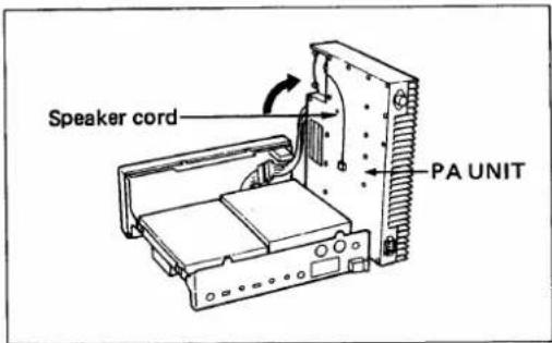
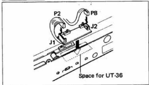
The voice synthesizer announces the displayed frequency when the [SPCH] SWITCH on the front panel is pushed.
- The UT-36 VOICE SYNTHESIZER UNIT should be installed on the bottom side as shown in the diagram.
1) Remove the top and bottom covers.
2) Remove the PA UNIT.
3) Remove the protective paper from the back of the UT-36 to expose the adhesive strip, and install the unit in the location shown in the bottom view of the transceiver.
4) Connect P8 (3 pins) from the LOGIC UNIT to J2 on the UT-36.
5) Connect P2 (5 pins) from the LOGIC UNIT to J1 on the UT-36.
6) Replace the top and bottom covers.
7) Refer to the UT-36 instruction sheet for operating instructions.
■ FL-32A CW NARROW FILTER
The FL-32A CW NARROW FILTER provides comfortable interference-free CW communications. (See page 42 for installation location.)
FL-32A CW NARROW FILTER : 500Hz/-6dB
■ CR-64 HIGH-STABILITY CRYSTAL UNIT
Remove X1 on the PLL UNIT and then install the CR-64 (See page 42) and perform the following.
1) Remove P1 from J2 on the RF-YGR UNIT and connect a frequency counter to P1.
2) Set display frequency to 440.000MHz and select FM mode, then adjust L22 on the PLL UNIT to 369.5485MHz.
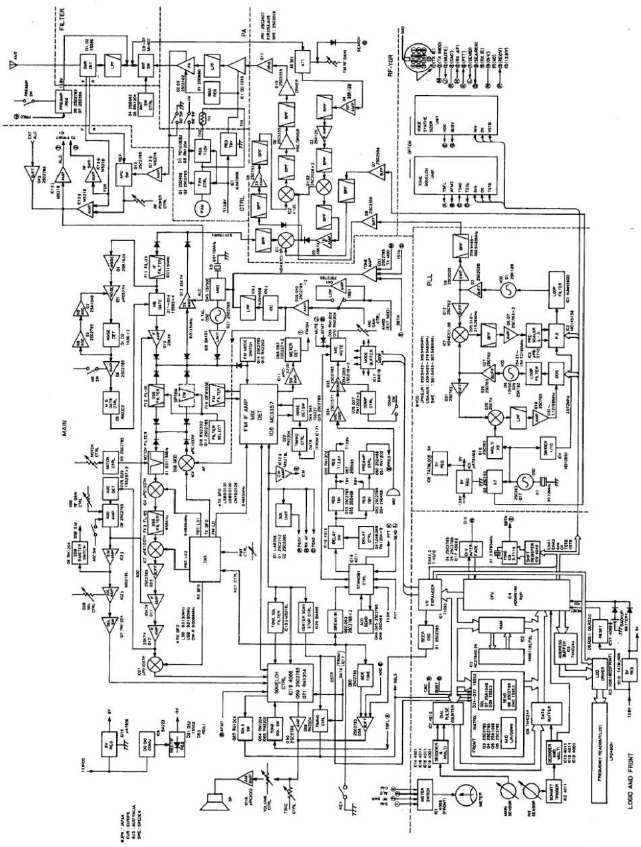
flowchart
graph TD
    subgraph MAIN
        A["Filter"] --> B["Resistor"]
        B --> C["Capacitor"]
        C --> D["Motor"]
        D --> E["Control Unit"]
        E --> F["PLL"]
        F --> G["Output"]
    end

    subgraph RF-YGR
        H["Resistor"] --> I["Capacitor"]
        I --> J["Motor"]
        J --> K["Control Unit"]
        K --> L["PLL"]
        L --> M["Output"]
    end

    subgraph MODE AND FRONT
        N["Resistor"] --> O["Capacitor"]
        O --> P["Motor"]
        P --> Q["Control Unit"]
        Q --> R["PLL"]
        R --> S["Output"]

    subgraph MAIN
        T["Resistor"] --> U["Capacitor"]
        U --> V["Motor"]
        V --> W["Control Unit"]
        W --> X["PLL"]
        X --> Y["Output"]

    subgraph MODE AND FRONT
        Z["Resistor"] --> AA["Capacitor"]
        AA --> AB["Motor"]
        AB --> AC["Control Unit"]
        AC --> AD["PLL"]
        AD --> AE["Output"]

    subgraph MAIN
        AF["Resistor"] --> AG["Capacitor"]
        AG --> AH["Motor"]
        AH --> AI["Control Unit"]
        AI --> AJ["PLL"]
        AJ --> AK["Output"]

    subgraph MODE AND FRONT
        AL["Resistor"] --> AM["Capacitor"]
        AM --> AN["Motor"]
        AN --> AO["Control Unit"]
        AO --> AP["PLL"]
        AP --> AQ["Output"]

    subgraph MAIN
        AR["Resistor"] --> AS["Capacitor"]
        AS --> AT["Motor"]
        AT --> AU["Control Unit"]
        AU --> AV["PLL"]
        AV --> AW["Output"]

    subgraph MODE AND FRONT
        AX["Resistor"] --> AY["Capacitor"]
        AY --> AZ["Motor"]
        AZ --> BA["Control Unit"]
        BA --> BB["PLL"]
        BB --> BC["Output"]

    subgraph MAIN
        BD["Resistor"] --> BE["Capacitor"]
        BE --> BF["Motor"]
        BF --> BG["Control Unit"]
        BG --> BH["PLL"]
        BH --> BI["Output"]

    subgraph MODE AND FRONT
        BJ["Resistor"] --> BK["Capacitor"]
        BK --> BL["Motor"]
        BL --> BM["Control Unit"]
        BM --> BN["PLL"]
        BN --> BO["Output"]

    subgraph MAIN
        BP["Resistor"] --> BQ["Capacitor"]
        BQ --> BR["Motor"]
        BR --> BS["Control Unit"]
        BS --> BT["PLL"]
        BT --> BU["Output"]

    subgraph MODE AND FRONT
        BV["Resistor"] --> BW["Capacitor"]
        BW --> BX["Motor"]
        BX --> BY["Control Unit"]
        BY --> BZ["PLL"]
        BZ --> CA["Output"]

    subgraph MAIN
        CB["Resistor"] --> CC["Capacitor"]
        CC --> CD["Motor"]
        CD --> CE["Control Unit"]
        CE --> CF["PLL"]
        CF --> CG["Output"]

    subgraph MODE AND FRONT
        CH["Resistor"] --> CI["Capacitor"]
        CI --> CJ["Motor"]
        CJ --> CK["Control Unit"]
        CK --> CL["PLL"]
        CL --> CM["Output"]

    subgraph MAIN
        CN["Resistor"] --> CO["Capacitor"]
        CO --> CP["Motor"]
        CP --> CQ["Control Unit"]
        CQ --> CR["PLL"]
        CR --> CS["Output"]

    subgraph MODE AND FRONT
        CT["Resistor"] --> CU["Capacitor"]
        CU --> CV["Motor"]
        CV --> CW["Control Unit"]
        CW --> CX["PLL"]
        CX --> CY["Output"]

    subgraph MAIN
        DD["Resistor"] --> DE["Capacitor"]
        DE --> DF["Motor"]
        DF --> DG["Control Unit"]
        DG --> DH["PLL"]
        DH --> DI["Output"]

    subgraph MODE AND FRONT
        DJ["Resistor"] --> DEU["Dial 100Hz/150Hz/200Hz/250Hz/300Hz/400Hz/50Hz/60Hz/70Hz/80Hz/90Hz/100Hz/110Hz/120Hz/130Hz/140Hz/150Hz/160Hz/170Hz/180Hz/190Hz/200Hz/210Hz/220Hz/230Hz/240Hz/250Hz/260Hz/270Hz/280Hz/290Hz/300Hz/310Hz/320Hz/330Hz/340Hz/350Hz/360Hz/370Hz/380Hz/390Hz/400Hz/410Hz/420Hz/430Hz/440Hz/450Hz/460Hz/470Hz/480Hz/490Hz/500Hz/510Hz/520Hz/530Hz/540Hz/550Hz/560Hz/570Hz/580Hz/590Hz/600Hz/610Hz/620Hz/630Hz/640Hz/650Hz/660Hz/670Hz/680Hz/690Hz/700Hz/710Hz/720Hz/730Hz/740Hz/750Hz/760Hz/770Hz/780Hz/790Hz/800Hz/810Hz/820Hz/830Hz/840Hz/850Hz/860Hz/870Hz/880Hz/890Hz/900Hz/910Hz/920Hz/930Hz/940Hz/950Hz/960Hz/970Hz/980Hz/990Hz/1000Hz<br><br>    subgraph MAIN<br>    BQA[Pump"] --> BQB["Pump Control"] & BQC["Pump Output"]

    subgraph MODE AND FRONT
    BQD["Pump"] --> BQE["Pump Control"] & BQF["Pump Output"]

    subgraph MAIN
    BQG["Pump"] --> BQH["Pump Control"] & BQI["Pump Output"]

    subgraph MODE AND FRONT
    BQJ["Pump"] --> BQK["Pump Control"] & BQL["Pump Output"]

    subgraph MAIN
    BQM["Pump"] --> BQN["Pump Control"] & BQO["Pump Output"]

    subgraph MODE AND FRONT
    BQP["Pump"] --> BQQ["Pump Control"] & BQR["Pump Output"]

    subgraph MAIN
    BQS["Pump"] --> BQW["Pump Control"] & BQX["Pump Output"]

    subgraph MODE AND FRONT
    BQX["Pump"] --> BQY["Pump Control"] & BQZ["Pump Output"]

    subgraph MAIN
    BQW["Pump"] --> BQX["Pump Control"] & BQY["Pump Output"]

    subgraph MODE AND FRONT
    BQX["Pump"] --> BQY["Pump Control"] & BQZ["Pump Output"]

    subgraph MAIN
    BQX["Pump"] --> BQY["Pump Control"] & BQZ["Pump Output"]

    subgraph MODE AND FRONT
    BQX["Pump"] --> BQY["Pump Control"] & BQZ["Pump Output"]

    subgraph MAIN
    BQX["Pump"] --> BQY["Pump Control"] & BQZ["Pump Output"]

    subgraph MODE AND FRONT
    BQX["Pump"] --> BQY["Pump Control"] & BQZ["Pump Output"]

    subgraph MAIN
    BZP["Pump"] --> BZQ["Pump Control"] & BZC["Pump Output"]

    subgraph MODE AND FRONT
    BZP["Pump"] --> BZQ["Pump Control"] & BZC["Pump Output"]

    subgraph MAIN
    BZP["Pump"] --> BZQ["Pump Control"] & BZC["Pump Output"]

    subgraph MODE AND FRONT
    BZP["Pump"] --> BZQ["Pump Control"] & BZC["Pump Output"]

    subgraph MAIN
    BZP["Pump"] --> BZQ["Pump Control"] & BZC["Pump Output"]

    subgraph MODE AND FRONT
    BZA["Pump"] --> BZA["Pump Control"] & BZA["Pump Output"]

    subgraph MAIN
    BZA["Pump"] --> BZA["Pump Control"] & BZA["Pump Output"]

    subgraph MODE AND FRONT
    BZA["Pump"] --> BZA["Pump Control"] & BZA["Pump Output"]

    subgraph MAIN
    BZA["Pump"] --> BZA["Pump Control"] & BZA["Pump Output"]

    subgraph MODE AND FRONT
    BZA["Pump"] --> BZA["Pump Control"] & BZA["Pump Output"]
To upgrade quality/ some components or frequency systems may be subject to change without notice.
13 SPECIFICATIONS
GENERAL
| • Frequency coverage | : U.S.A. version | 430.0000 ~ 450.0000MHz | ||
| Europe version | 430.0000 ~ 440.0000MHz | |||
| Australia version | 430.0000 ~ 450.0000MHz | |||
| Sweden version | 432.0000 ~ 438.0000MHz | |||
| • Number of memory channels | : 99 channels Plus P1, P2 and CALL CHANNEL | |||
| • Antenna impedance | : 50Ω unbalanced | |||
| • Frequency stability | : ±5ppm (0°C ~ +50°C) | |||
| • Power supply requirement | : 13.8VDC ±15% | |||
| • Current drain (at 13.8V DC) | : Transmitting | At 75W output | Approx. | 20A |
| At 10W output | Approx. | 8A | ||
| Receiving | At maximum audio output | Approx. | 1.3A | |
| Squelched | Approx. | 1.1A | ||
| • Dimensions | : 241(244)mm(W) x 95(108)mm(H) x 239(277)mm(D) Bracketed values include projections. | |||
| • Weight | : 6.0kg | |||
| • Usable temperature range | : -10°C ~ +60°C | |||
■ TRANSMITTER
| • Emission modes | : FM (F3), SSB (A3J), CW (A1) |
| • RF output power | : 10 ~ 75W continuously adjustable |
| • Modulation system | : FM Variable reactance frequency modulationSSB Balanced modulation |
| • Maximum frequency deviation | : ±5kHz (FM mode) |
| • Spurious output | : More than 60dB below peak output power |
| • Carrier suppression | : More than 40dB below peak output power |
| • Unwanted sideband | : More than 40dB down with 1000Hz AF input |
| • Microphone impedance | : 600Ω |
RECEIVER
| Receive system | : Quadruple conversion superheterodyne (SSB, CW)Triple conversion superheterodyne (FM) | |
| Receive modes | : FM (F3), SSB (A3J), CW (A1) | |
| Intermediate frequencies | : 1st 70.4515MHz (FM, SSB) 70.4506MHz (CW)2nd 9.0115MHz (FM, SSB) 9.0106MHz (CW)3rd 455kHz (All modes)4th 9.0115MHz (SSB) 9.0106MHz (CW) | |
| Sensitivity | : FM Less than 0.18μV for 12dB SINADLess than 0.25μV for 20dB NQLSSB, CW Less than 0.1μV for 10dB S/N | |
| Squelch sensitivity | : FM Less than 0.14μVSSB Less than 0.56μV | |
| Selectivity | : FM 15.0kHz/−6dB 30.0kHz/−60dBSSB, CW 2.3kHz/−6dB 4.0kHz/−60dB | |
| Spurious response rejection | : More than 70dB | |
| Audio output impedance | : 8Ω | |
| Audio output power | : More than 2W at 10% distortion with an 8Ω load | |
| RIT variable range | : ±9.99kHz | |
4 OPTIONS
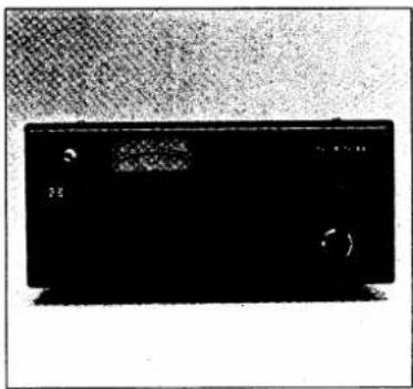
natural_image
Black rectangular electronic device with a display screen and control buttons (no visible text or symbols)IC-PS30 SYSTEM POWER SUPPLY 13.8V, 25A
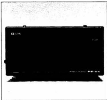
natural_image
Black rectangular electronic device with mounting feet and a small logo on top (no readable text or symbols)PS-55 AC POWER SUPPLY 13.8V, 20A
natural_image
Black-and-white photo of a desktop computer monitor and keyboard (no visible text or symbols)SP-7 EXTERNAL SPEAKER
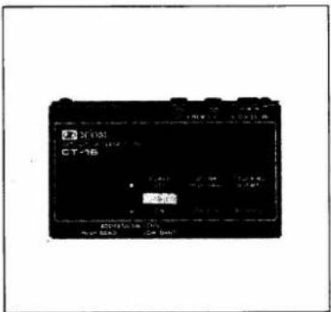
CT-16 SATELLITE INTERFACE UNIT
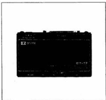
CT-17 CI-V LEVEL CONVERTER
natural_image
Close-up of a black rectangular object mounted on a vertical pole, possibly a switch or bracket (no visible text or symbols)AG-35 WEATHERPROOF 430MHz PREAMPLIFIER
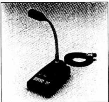
natural_image
Black-and-white photo of a desktop desk lamp with a curved neck and attached strap (no visible text or symbols)SM-8 DESK MICROPHONE
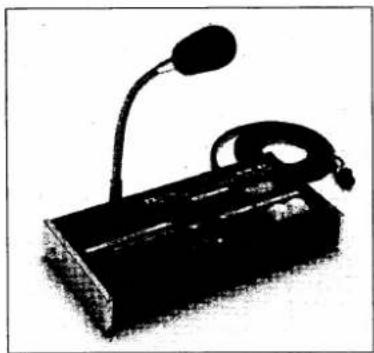
natural_image
Black-and-white photo of a desktop computer with a neck lamp and cord (no visible text or symbols)SM-10 COMPRESSOR/GRAPHIC EQUALIZER DESK TOP MICROPHONE
natural_image
Black rectangular object with a textured top, resting on a textured dark surface (no visible text or symbols)CR-64 HIGH-STABILITY CRYSTAL UNIT
| UT-34 | Tone Squelch Unit |
| UT-36 | Voice Synthesizer Unit |
| FL-32A | CW Narrow Filter (500Hz at -6dB point) |
| IC-MB5 | Mobile Mounting Bracket |
| MB-23 | Carrying Handle |
•MEMO•
Please record the serial number of your IC-475H transceiver below for future servicing reference:
Serial number :
Date of purchase : ____
Place where purchased : ____
- 10-475H
- FOREWORD
- TABLE OF CONTENTS
- UNPACKING
- PRECAUTIONS AND PREPARATIONS
- ■ INSTALLATION LOCATIONS
- ■ GROUNDING
- OPERATING
- 210EETURES
- ■ ICOM'S NEWLY DEVELOPED STATE-OF-THE-ART FREQUENCY SYNTHESIZER
- ■ NEWLY DEVELOPED ICOM CPU INSTALLED
- ■ OUTSTANDING RECEIVER PERFORMANCE
- ■ COMPLETE UHF TRANSCEIVER
- ■ OPERATIONS AVAILABLE
- CONTROL FUNCTIONS
- 3-1 FRONT PANEL
- 3-2 FREQUENCY DISPLAY
- 3-3 REAR PANEL
- INSTALLATION
- - 1 PLANNING
- 4-2 MOUNTING THE TRANSCEIVER
- Mobile installations:
- 4-3 ANTENNA
- ●TYPE-N CONNECTOR INSTALLATION
- - 4 GROUNDING
- INTERCONNECTIONS
- 5-1 POWER SUPPLY
- 5-2 CONNECTING A LINEAR AMPLIFIER
- 5-3 CONNECTING AN AFSK TERMINAL UNIT
- 5-4 MIC CONNECTOR INFORMATION
- - 5 ACC (1) SOCKET INFORMATION
- 5-6 AQS SOCKET INFORMATION
- 5-7 REMOTE CONTROL JACK (CI-V) INFORMATION
- Switches 1 \~ 7 (for setting an address with your transceiver):
- Switch 8 (For setting a transceive flag):
- NOTE:
- SATELLITE COMMUNICATIONS
- GENERAL OPERATION
- 6-1 INITIAL SETTINGS
- Front panel switch and control settings
- Rear panel switch settings
- 6-2 FM OPERATION
- FM Receiving
- 6-3 SSB OPERATION
- 6-4 CW OPERATION
- CW receiving
- • BREAK-IN OPERATION
- 6-5 PACKET AND AMTOR OPERATIONS
- 6-6 RTTY OPERATION
- Receiving:
- Transmitting:
- 6-7 SSTV OPERATION
- FUNCTIONS OPERATION
- 7-1 SPEECH COMPRESSOR OPERATION
- 7-2 PREAMP SWITCH OPERATION
- 7-3 AGC OPERATION
- - 4 NOISE BLANKER (NB) OPERATION
- - 5 SUBAUDIBLE TONE ENCODER AND 1750Hz TONE CALL OPERATIONS
- 7-6 DUPLEX (SPLIT FREQUENCY) OPERATION
- Programming the offset frequency
- - Duplex operation using 7.6MHz offset frequency
- 7-7 DATA SWITCH OPERATION
- 7-8 PASSBAND TUNING (PBT) OPERATION
- 7-9 NOTCH FILTER OPERATION
- - 10 RIT OPERATION
- - 11 MICROPHONE UP/DOWN OPERATION
- 7-12 SWR READING OPERATION
- Microphone UP/DOWN ON-OFF SWITCHES:
- MEMORY AND SCANNING OPERATION
- 8-1 VFO A AND B SELECTION
- 8-2 MEMORY CHANNEL AND VFO SELECTION
- 8-4 PROGRAMMING MEMORY CHANNELS
- 8-5 PROGRAMMING THE CALL CHANNEL
- Programming the CALL CHANNEL
- Recalling CALL CHANNEL information
- 8-6 MEMORY CLEARING
- 8-7 SCANNING OPERATION
- S MAINTENANCE AND ADJUSTMENT
- - 1 MAINTENANCE
- NOTE: Bargeplacement should be gone by unauthorized IT COM Dealer or COM Service Center
- NOTE: A large number program management channels will be tested in the scenarios recently.
- - 2 ADJUSTMENTS
- Brake adjustment
- Display light dimmer adjustment
- Beep sound level adjustment
- OINSIDE VIEWS
- THE OPTION INSTALLATIONS
- ■ TRANSCEIVER DISASSEMBLY
- SPECIFICATIONS
- OPTIONS
- •MEMO•
Marke : ICOM
Modell : IC-475H
Kategorie : Empfänger