
IC-4KL - Empfänger ICOM - Kostenlose Bedienungsanleitung
Finden Sie kostenlos die Bedienungsanleitung des Geräts IC-4KL ICOM als PDF.


| Produkttyp | HF-Linearverstärker (1 kW) |
| Marke | ICOM |
| Modell | IC-4KL |
| Frequenzabdeckung | 1,8 – 29,7 MHz (alle Amateurfunkbänder; 24–28 MHz entfällt in der US-Version) |
| Ausgangsleistung (CW/RTTY) | 1 kW bei 200–240 V AC; 500 W bei 100–120 V AC |
| Ausgangsleistung (SSB) | 1 kW PEP bei 200–240 V AC; 500 W PEP bei 100–120 V AC |
| Treiberleistung | 100 W max. |
| Eingangsimpedanz | 50 Ω (unsymmetrisch) |
| Antennentuner | Vollautomatisch, abstimmbarer Bereich 16,7–150 Ω (VSWR ≤3:1), Geschwindigkeitsoptimierung durch Speicher |
| Schutzschaltungen | Überstrom, Übertemperatur (Kühlkörper >90°C), SWR >2:1, Treiberleistung >100 W, ALC-Regelung, PA-Unwucht |
| Netzteil | Integriertes Schaltnetzteil 40 V / 60 A, automatische Umschaltung 100–120 V AC / 200–240 V AC |
| Fernbedienung | Separates Bedienteil mit allen Anzeigen und Schaltern |
| Gewicht (Verstärker) | 36,0 kg (79,4 lb) |
| Gewicht (Fernbedienung) | 2,7 kg (6,0 lb) |
| Abmessungen (Verstärker) | 425 × 297 × 458,5 mm (16,7 × 11,7 × 18,1 Zoll) |
| Abmessungen (Fernbedienung) | 200 × 149 × 341 mm (7,9 × 5,9 × 13,4 Zoll) |
| Betriebstemperaturbereich | −10 °C bis +40 °C (+14 °F bis +104 °F) |
| Reinigung | Mit trockenem, weichem Tuch reinigen; keine aggressiven Reinigungsmittel (Benzin, Alkohol) verwenden |
| Sicherheitshinweise | Hochspannung! Niemals Antennenstecker bei Netzanschluss berühren. Gerät nur geerdet betreiben. Transport nur zu zweit (36 kg). Keine Verlängerungskabel verwenden. Vor Inbetriebnahme ALC-Abgleich durchführen. |
| Lieferumfang | Steuerkabel (3 m), Koaxialkabel (3 m), ACC-Kabel (3 m), Rack-Einbauwinkel und Schrauben |
Häufig gestellte Fragen - IC-4KL ICOM
Benutzerfragen zu IC-4KL ICOM
0 Frage zu diesem Gerät. Beantworten Sie die, die Sie kennen, oder stellen Sie Ihre eigene.
Eine neue Frage zu diesem Gerät stellen
Laden Sie die Anleitung für Ihr Empfänger kostenlos im PDF-Format! Finden Sie Ihr Handbuch IC-4KL - ICOM und nehmen Sie Ihr elektronisches Gerät wieder in die Hand. Auf dieser Seite sind alle Dokumente veröffentlicht, die für die Verwendung Ihres Geräts notwendig sind. IC-4KL von der Marke ICOM.
BEDIENUNGSANLEITUNG IC-4KL ICOM
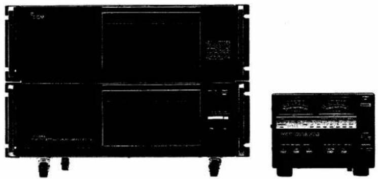
HF ALL BAND
1 kW LINEAR AMPLIFIER
IC-4KL
natural_image
Two black electronic devices: a front-mounted display unit and a control panel (no visible text or symbols)FOREWORD
Thank you for purchasing Icom's advanced new IC-4KL 1 kW LINEAR AMPLIFIER. The IC-4KL provides output of 1 kW and is designed with the very latest in high-tech features. The IC-4KL's fully automatic, high-speed antenna tuner and automatic input-selectable AC power supply are unique in today's market.
Please read this instruction manual carefully and thoroughly before operating your new IC-4KL. For further information, please feel free to contact your nearest Icom Dealer or Service Center.
IMPORTANT
(1) READ THIS INSTRUCTION MANUAL CAREFULLY before attempting operation. If you have any questions regarding the operation of the IC-4KL, feel free to contact your nearest authorized Icom Dealer or Service Center.
(2) SAVE THIS INSTRUCTION MANUAL – This instruction manual contains important safety and operating instructions for the IC-4KL.
(3) The U.S.A. version does not include the 24\~28 MHz band range.
EXPLICIT DEFINITIONS
| WORD | DEFINITIONS |
| WARNING | Personal injury, fire hazard or electric shock may occur. |
| CAUTION | Equipment damage may occur. |
| NOTE | If disregarded, inconvenience only. No personal injury, risk of fire or electric shock. |
PRECAUTIONS
HIGH VOLTAGE! NEVER touch the antenna connector or the power supply section in the linear amplifier while connecting the IC-4KL to an AC outlet.
WARNING - NEVER carry the linear by yourself. At least two persons must carry the linear amplifier since it weighs approx. 36 kg (79.4 lb).
NEVER expose the IC-4KL to rain or moisture as fire or shock hazard could occur.
NEVER use the linear amplifier if it is ungrounded as electrical shock, TVI, BCI and other problems could occur.
NEVER use an extension cord with the AC power cable. Extension cords may cause fires and electric shocks.
NEVER touch the IC-4KL with metal strips, wires, etc. These materials may cause fires and electric shocks.
NEVER allow children to touch the IC-4KL or the remote controller.
DO NOT use the IC-4KL before adjusting the [ALC ADJ] control on the rear panel of the linear amplifier.
AVOID using or placing the IC-4KL or remote controller in areas with temperatures below -10^ (+14°F) or over +40^ (+104°F).
AVOID using in excessively dusty environments.
ALWAYS operate with 500 W output power with a 100 \~ 120 V AC power source. See p. 12 for the selector switch location.
The IC-4KL cannot turn power ON when an Icom HF transceiver is not connected.
TABLE OF CONTENTS
FOREWORD i
IMPORTANT.... i
EXPLICIT DEFINITIONS.... i
PRECAUTIONS.... i
TABLE OF CONTENTS.... ii
UNPACKING.... ii
1 FEATURES.... 1
2 PANEL DESCRIPTION.... 2\~4
2 - 1 Linear amplifier .... 2
2 - 2 Remote controller.... 3
3 INSTALLATION 5\~6
3-1 Unpacking 5
3 - 2 Setting location. 5
3 - 3 AC power cable connection. . . . . . . . . . . . 5
3-4 Antenna system 5
3 - 5 Ground system .... 5
3-6 Handle installation.... 6
3 - 7 ACC socket information....6
4 SYSTEM INTERCONNECTIONS ..... 7
5 OPERATION....8\~10
5-1 Cautions 8
5-2 Presettings 8
5-3 ALC presetting 8
5-4 Operation 9
5 - 5 Protector circuit information. . . . . . . . . . . . 10
5-6 Antenna tuner information.... 10
6 MAINTENANCE.... 11
6-1 Troubleshooting 11
6-2 CPU backup battery.... 11
6-3 Cleaning 11
7 INSIDE VIEW.... 12
8 CIRCUIT DESCRIPTION .... 13\~14
8-1 Linear amplifier circuits 13
8-2 Antenna tuner circuit....14
9 BLOCK DIAGRAM 15
10 SPECIFICATIONS 16
SCHEMATIC DIAGRAM..... SEPARATE
UNPACKING
natural_image
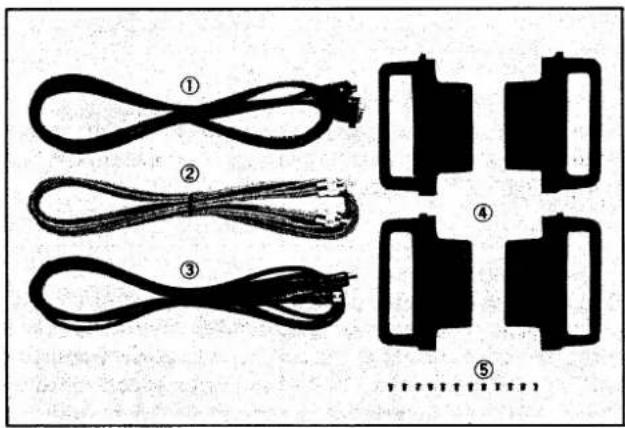
Diagram showing five types of cable connectors and plastic components, no text or symbols presentAccessories included with the IC-4KL: Qty.
① Control cable (3 m; 10 ft) 1
② Coaxial cable (3 m; 10 ft) 1
③ ACC cable (3 m; 10 ft)....1
④ Rack mounting handles 4
⑤ Rack mounting handle screws....12
1 kW OUTPUT AT FULL DUTY CYCLE
The power amplifier consists of 4 push-pull amplifiers (a total of 8 2SC2652 power transistors), ensuring stable 1kW^* output power with clean and low distortion. An extra-large heatsink and efficient cooling system are installed for full duty ^2 operation.
*1 800 W of output power on 24.5 and 28 MHz bands (Not included in the U.S.A. version).
*2 Full duty operation is accepted when using 200 \~ 240 V AC as a power source and the built-in antenna tuner is OFF.
SEPARATED CONTROLLER AND AMPLIFIER
The remote controller and linear amplifier can be used independently. The remote controller can be placed on the side of the transceiver and the linear amplifier can be set under a desk, on the floor or in any required location.
FULLY AUTOMATIC, HIGH-SPEED ANTENNA TUNER
A built-in, fully automatic antenna tuner provides instant antenna matching conditions during QSYs. No need to ever worry about manual antenna matching.
The antenna tuner is equipped with an advanced feature that memorizes previously matched conditions on each band and then starts tuning from the memorized condition. The tuner therefore very quickly tunes when the previous frequency is selected.
If complete tuning cannot be made starting from the memorized condition, an advanced re-try function changes a preset position, then tunes it again for complete tuning.
The perfect tuning system with rapid speeds and no preset controls.
FULL BREAK-IN OPERATION
High-speed switching relays are used to maintain full break-in operation. The IC-4KL lets you operate CW full break-in with 1 kW output power.
COMPLETE PROTECTION CIRCUITS
Protection circuitry includes an ALC line control and amplifier loads for protection against high internal temperatures, excessive current at the collectors of power transistors, etc. In addition, the ALC line of an exciter is controlled by the IC-4KL CPU to prevent damage to the band switching relay from band changing during transmission.
OTHER OUTSTANDING FEATURES
- Built-in 40 V, 60 A switching power supply with automatic selection for use with 100 \~ 120 V AC or 200 \~ 240 V AC input.
- Two needle meters that show SWR, final transistor collector current, output power, final transistor temperature, etc.
- Rack mounting handles for mounting with a 19-inch rack.
- Simple connection design for use with an Icom transceiver. Just connect a few cables.
2-1 Linear amplifier
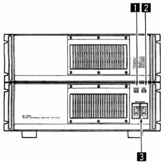
- Front panel
●Rear panel
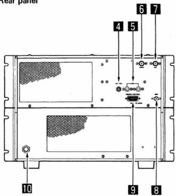
1 OVERLOAD INDICATOR [OVERLOAD]
Lights if the power supply reaches the following conditions and the protection circuit is activated.
| ITEM | DESCRIPTION |
| Over current | More than 38 A ±2.7 A DC (at 100~120 V AC input) More than 60 A ±1 A DC (at 200~240 V AC input) |
| Output load | Less than 8 V DC of the output voltage |
| High voltage output | 47~52 V DC of the output voltage |
| High temperature | More than 80°C on the heatsink |
To turn ON the power again when the indicator lights, turn OFF [POWER] on the remote controller and wait until the indicator goes out. Then turn ON [POWER] again.
2 POWER INDICATOR [POWER]
Lights when [POWER] to the remote controller is turned ON.
3 CIRCUIT BREAKER
Cuts off the AC input when over current occurs.
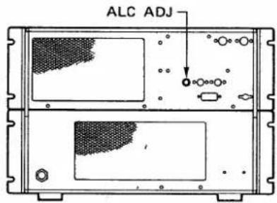
4 ALC ADJUSTMENT CONTROL [ALC ADJ]
Sets an ALC level of the connected exciter (transceiver). Adjust this control using the protection level meter on [METER 2]. The control is covered with a cap nut.
5 ACC SOCKETS [ACC]
Connect the exciter through the supplied ACC cable. These sockets are also used for connecting an external unit such as the EX-627 HF AUTOMATIC ANTENNA SELECTOR. The sockets are parallel-connected.
6 POWER INPUT CONNECTOR [INPUT]
Connects the antenna connector of an exciter (transceiver) using the supplied coaxial cable.
7 ANTENNA CONNECTOR [ANT]
Connects a 50 Ω antenna using a PL-259 connector through a 50 Ω coaxial cable. Power rating of the antenna must be 1 kW or more.
8 GROUND TERMINAL [GND]
Connect this terminal to ground to prevent electrical shocks, TVI, BCI and other problems. Use the heaviest gauge wire or strap available and make the connection as short as possible.
9 REMOTE CONTROL SOCKET
Connects the remove controller through the supplied control cable.
10 AC POWER CABLE
Connects to an AC outlet. Input voltage of 100 \~ 120 V or 200 \~ 240 V is automatically switched inside the linear amplifier.
Use 200 \~ 240 V AC when operating 1 kW output and in full-duty cycle.
2 PANEL DESCRIPTION
2-2 Remote controller
- Front panel
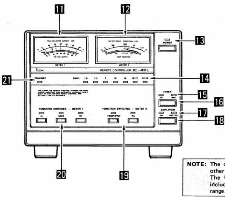
NOTE: The diagram shown at left is other than the U.S.A. version. The U.S.A. version does not include the 24 \~ 28 MHz band range.
11 FUNCTION METER 1 [METER 1]
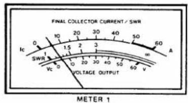
Shows Ic (final collector current), SWR or Vc (final collector voltage) selected by the [METER 1] switches 20
12 FUNCTION METER 2 [METER 2]
Shows temperature, protection level or output power selected by the [METER 2] switches 19 and the [PRO/TEMP] switch 22 on the rear panel.
13 POWER SWITCH [POWER]
Turns ON and OFF the main power of the remote controller and linear amplifier.
14 BAND INDICATORS [BAND]
Indicate the operating bands. Operating bands are automatically changed by an Icom transceiver connected to the IC-4KL.
The 24 \~ 28 MHz band range is not available in the U.S.A. version.
15 TUNER INDICATORS [ON] [WAIT]
| INDICATOR | DESCRIPTION |
| [ON] | Lights when the [TUNER] switch is ON. |
| [WAIT] | Lights while the antenna tuner is tuning. The indicator goes out when an antenna matching is made. |
17 LINEAR AMPLIFIER INDICATOR [ON] [PROTECT]
| INDICATOR | DESCRIPTION |
| [ON] | Lights when the power amplifier is ON. |
| [PROTECT] | Lights when a protector circuit is activated and the linear amplifier is bypassed. |
18 LINEAR AMPLIFIER SWITCH [AMPLIFIER]
Turns ON and OFF the power amplifier in the linear amplifier.
19 METER 2 SWITCHES [METER 2]
Select the following switch positions.
| SWITCH | DESCRIPTION |
| [TEMP/PRO] | Shows heatsink temperature or the ALC protection level. These are selected by the [PRO/TEMP] switch on the rear panel.CAUTION: Stop transmitting when the [TEMP] meter is in the red zone, otherwise the protection circuit may reduce the output power or bypass the power amplifier. |
| [Po] | Shows output power. |
16 TUNER SWITCH
Turns ON and OFF the built-in antenna tuner.
•Rear panel
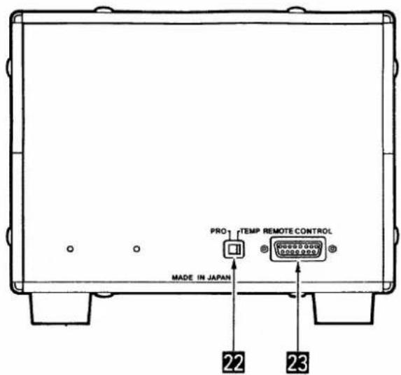
20 METER 1 SWITCHES [METER 1]
Select the following switch positions.
| SWITCH | DESCRIPTION |
| [Ic] | Shows the amount of final transistor collector current. |
| [SWR] | Shows the antenna system SWR. |
| [Vc] | Shows the final transistor collector voltage. |
21 TRANSMIT INDICATOR [TRANSMIT]
Lights when the linear amplifier is ON and transmitting.
22 PROTECTION/TEMPERATURE SELECTOR SWITCH [PRO/TEMP]
Selects the protection level or final transistor temperature value related with the [TEMP/PRO] switch [19] on the remote controller front panel.
23 REMOTE CONTROL SOCKET
Connects the linear amplifier through the supplied control cable.
CAUTION: Two persons are required to lift the IC-4KL together when unpacking the linear amplifier from the shipping carton or moving it at a later time. The IC-4KL is very heavy.
3-1 Unpacking
Carefully remove the linear amplifier from the packing carton and examine it for signs of shipping damage. If damage is apparent, notify the delivering carrier or dealer immediately, stating the full extent of the damage.
Packing cartons should be kept for storing, moving, or reshipping the linear amplifier. For a description and diagram of accessory equipment included with the IC-4KL, see UNPACKING on page ii.
3-2 Setting location
Select a location for the IC-4KL remote controller and linear amplifier that allows good ventilation and access to the front panel. Keep away from extreme heat, cold, vibrations and electro-magnetic sources.
The remote controller should be placed near the operator for easily monitoring linear amplifier conditions at any time.
The linear amplifier must be placed in a solid location such as on a floor since the unit is very heavy.
3-3 AC power cable connection
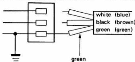
A suitable AC power plug must be connected to the AC power cable end. See the diagram below for connection procedures.
The IC-4KL can accept either 100 \~ 120 V AC or 200 \~ 240 V AC power. However, we recommend using 200 \~ 240 V AC rather than 100 \~ 120 V AC for better power supply efficiency and longer periods of transmission.
3-4 Antenna system
Use a well-matched 50 Ω antenna with a power rating of more than 1 kW. Use a 50 Ω coaxial cable as a feedline with a PL-259 connector. The coaxial cable should be thicker than a RG-94/U coaxial cable. See p. 6 for PL-259 connector installation.
3-5 Ground system
To prevent electrical shocks, TVI, BCI and other problems, ground both the IC-4KL linear amplifier and the exciter (transceiver) through the ground terminals. For best results, use the heaviest gauge wire or strap available and make the connection as short as possible.
NEVER use a gas pipe or electrical conduit pipe for grounding.
- AC power cable connection
(1) Single-phase 3-wire line (200 \~ 240 V AC)
(2) Single-phase 2-wire line (100 \~ 120 V AC)
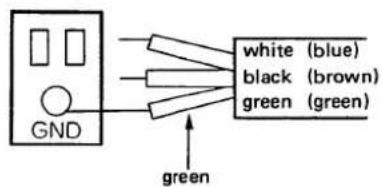
(3) Three-phase 3-wire line (200 \~ 240 V AC)
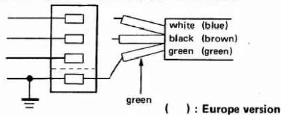
- The green wire from the AC power cable must be connected to the ground wire.
-
The black and white wires from the AC power cable can be connected to either terminal.
-
The green wire from the AC power cable must be connected to the ground wire.
-
The black wire from the AC power cable must be connected to the hot end (live) wire.
-
The white wire from the AC power cable must be connected to the return end wire.
-
The green wire from the AC power cable must be connected to the ground wire.
-
The black and white wires from the cable can be connected to 2 of 3 wires.
- PL-259 connector installation
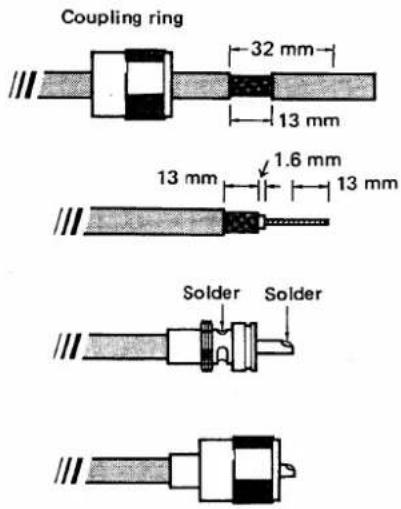
(1 mm = 1/32 in)
1) Slide the coupling ring over the coaxial cable. Strip the cable jacket to approx. 10 mm (3/8 in). Soft solder the exposed braid.
2) Strip the cable as shown in the diagram at left. Tin the center conductor the entire length of the exposed braid.
3) Slide the connector body over the cable and solder as shown at left.
4) Screw the coupling ring onto the connector body.
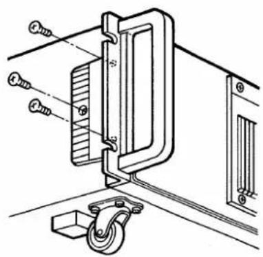
3-6 Handle installation
natural_image
Technical line drawing of a mechanical assembly with pulley and mounting bracket (no text or symbols)3-7 ACC socket information
1) Remove 2 screws from each side of the front panel.
2) Attach the supplied handles to the sides of the linear amplifier using the supplied screws as shown in the diagram at left.
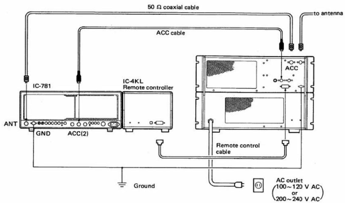
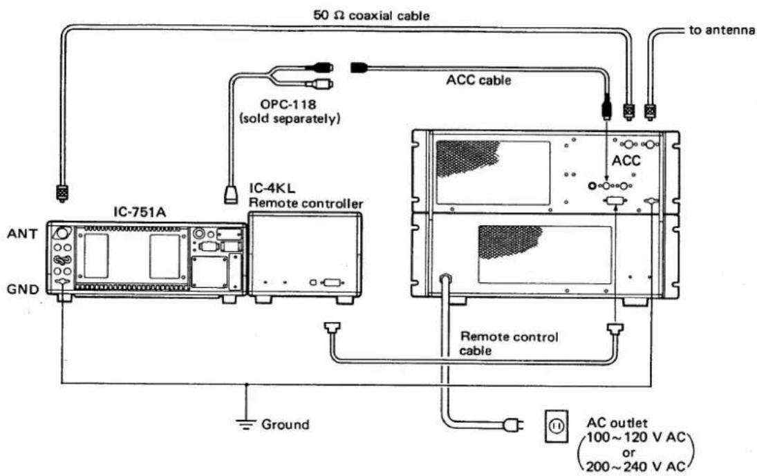
2 ACC sockets are installed on the linear amplifier rear panel. These 2 sockets are parallel connected inside the unit. One of these sockets is used to connect the supplied ACC cable to the ACC(2) socket of an Icom HF transceiver. Use another connector for connecting an external unit.
| ACC SOCKET | PIN NO. | PIN NAME | DESCRIPTION | SPECIFICATIONS |
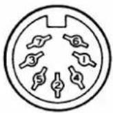 | 1 | 8 V | Regulated reference 8 V DC input for band changing. | Input voltage : 8 V DC ±0.3 VInput current : Less than 10 mA |
| 2 | GND | Ground terminal. | —— | |
| 3 | SEND | When grounded, transmits. | Ground level : -0.5 V ~ +0.8 V | |
| 4 | BAND | Band voltage input terminal. | Input voltage : 0 ~ +8 V | |
| 5 | ALC | ALC signal output terminal. | Output impedance : 10 kΩControl voltage : -4 ~ 0 V | |
| 6 | NC | No connection. | —— | |
| 7 | 13.8 V | 13.8 V DC input terminal. | Input current : Less than 1 A |
An Icom 100 W HF transceiver can be connected as an exciter to the IC-4KL. Non-Icom transceivers cannot be used since the IC-4KL is designed for special signals for synchronized band switching for each operating band.
See the following diagrams for making connections between the IC-4KL and an exciter (transceiver). See p. 5 for AC power plug connections.
●With 7-pin and 8-pin connectors
- With 24-pin connector
5-1 Cautions
5-2 Presettings
- DO NOT operate the IC-4KL before setting the ALC level with the [ALC ADJ] control. See the table below for the setting.
- AVOID CONTINUOUSLY operating the IC-4KL with full output power for more than 1 minute when using 100 \~ 120 V AC power. If 100 \~ 120 V AC power is used, operate at the ratio of 1 minute for transmit and 3 minutes for receive in 500 W.
After installation and connections are completed, set the switches as follows:
| REMOTE CONTROLLER | LINEAR AMPLIFIER | EXCITER (Transceiver) | |||
| POWER | OFF | ALC ADJ | Maximum counter-clockwise | Power | OFF |
| TUNER | OFF | Emission mode | CW or RTTY | ||
| AMPLIFIER | OFF | ||||
| METER 1 | Ic | CIRCUIT BREAKER | OFF | Output power Tx/Rx | MaximumReceive |
| METER 2 | Po | ||||
| TEMP/PRO | PRO | Meter | Po (Power) | ||
To rotate the [ALC ADJ] control, unscrew and remove the cap nut.
1) Turn ON the [CIRCUIT BREAKER] and [POWER] switches then turn ON the exit power.
2) Change the operating band on the exciter.
- Confirm that the [BAND] indicators on the remote controller show the correct band position.
3) Push [TUNER] switch ON.
- The green tuner indicator lights and the red [WAIT] indicator lights for a while.
4) Push the [AMPLIFIER] switch ON.
• The green indicator lights.
The ALC circuit controls the IC-4KL output power for controlling the exciter's output power through the ALC line.
CAUTION: Final power transistors may be damaged if the ALC control is set at a wrong position.
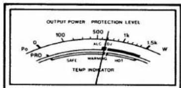
METER 2
1) Set the switches of the IC-4KL and the exciter as described in Section 5-1 above.
2) Turn ON the [CIRCUIT BREAKER] and [POWER] switches then turn ON the exciter power.
3) Push [TEMP/PRO] in the [METER 2] switch.
- Be sure the remote controller rear panel [PRO/TEMP] is set to [PRO].
4) Transmit with the exciter in CW or RTTY mode with full output power.
5) Adjust the [ALC ADJ] control on the linear amplifier rear panel to the reading of "ALC ADJ" point on METER 2.
6) Return the exciter to receive, and re-attach the cap nut on the [ALC ADJ] control.
5 OPERATION
5-4 Operation
![[PRO-TEMP]](/content/2026/05/777922/images/108dc284a2a3da6e6df8457692f2a678278599f0a1478818fe46321bac590001.jpg)
![METER 1 : [SWR] [LINEAR] [TUNER]](/content/2026/05/777922/images/96f6dd6b8d6fdfcfa29c265a4b1a1933bde8d55032c2b6a06d2dcaf4b878fb27.jpg)
CAUTION:
- DO NOT operate the IC-4KL before setting the ALC level with the [ALC ADJ] control. See p. 8 for the setting.
- AVOID operating the IC-4KL with full output power for more than 1 minute CONTINUOUSLY when using 100 \~ 120 V AC power. If 100 \~ 120 V AC power is used, operate at the rate of 1 minute for transmitting and 3 minutes for receiving in 500 W.
1) Set the switches on the remote controller, linear amplifier and the exciter as described on p. 8.
2) Turn ON the [CIRCUIT BREAKER] and [POWER] switches then turn ON the exciter power.
3) Set the exciter in CW or RTTY mode with minimum output power.
4) Set [PRO/TEMP] on the remote controller rear panel to the "TEMP" position.
5) Turn ON the [TUNER] and [AMPLIFIER] on the remote controller.
6) Transmit with the exciter and adjust the output power with the RF output power control on the exciter.
- See the exciter's instruction manual for transmitting.
7) The built-in antenna tuner automatically tunes antenna matching.
- SWR reading on METER 1 should be less than 1.2.
- The [WAIT] indicator lights while the tuner is tuning.
- The [WAIT] indicator blinks when the internal antenna tuner cannot tune and SWR exceeds 3.
8) When operating over long periods, push IN [TEMP/PRO] on the remote controller to monitor the linear amplifier condition.
- If the METER 2 (temperature meter) reading is in the red "HOT" zone, the exciter should be returned to receive, otherwise the protection circuit may be activated and the linear amplifier may be OFF.
Tech Talk from Icom
Q. How does the IC-4KL antenna tuner advance?
The antenna tuner has two major advanced features:
- the re-try function.
- tuning data memory capability.
The are based on Icom microprocessor technology and each feature is controlled by a 4-bit CPU.
The re-try function means that the built-in antenna tuner automatically changes the position of the variable capacitors to tune antenna matching if the
antenna tuner cannot tune from a previously memorized position of the variable capacitors.
The antenna tuner repeats this operation up to 3 times to cover any frequency in the operating band. So, the antenna tuner is fully automatic and no manual tuning is ever necessary.
Tuning data memory capability means that the CPU memorizes previously matched conditions. When the same frequency as the one previously used is selected, the antenna tuner automatically and quickly returns to the previous condition without transmitting unlike in older system.
5-5 Protector circuit information
When the red [PROTECT] indicator lights, the protector circuit is activated to bypass the linear amplifier. Check the reason for this as follows:
1) Push the [TEMP/PRO] switch.
- If the METER 2 indication is in the "HOT" zone, wait until the meter indication returns to the "SAFE" zone. The temperature protector is automatically reset.
2) Push the [SWR] switch.
- If the METER 1 reading is more than 3, check and adjust the antenna until the SWR is reduced.
3) Turn [AMPLIFIER] OFF and ON again, then push the [Ic] switch.
- If the METER 1 reading is more than 50 A, set the ALC level again. See Section 5-3 ALC presetting.
●Output power of the linear amplifier decreases when:
- the SWR is more than 2:1.
- the driving power exceeds 100 W.
- the output power exceeds 1 kW.
- the final collector current exceeds the limit.
●The linear amplifier is bypassed when:
- the power amplifier gain exceeds the limit.
- the power amplifier balance in the PA UNIT is broken.
- the heatsink temperature exceeds +90°C (+194°F).
5-6 Antenna tuner information
The built-in automatic antenna tuner can match the antenna feedline impedance to 50 Ω when the feedline impedance is within 16.7 \~ 150 Ω (VSWR 3:1).
Use of the antenna tuner greatly reduces overload for the final stage of the linear amplifier and eliminates harmonic radiation effectively.
For your reference, the following diagram shows graphically coaxial cable loss due to high SWR.
●SWR loss
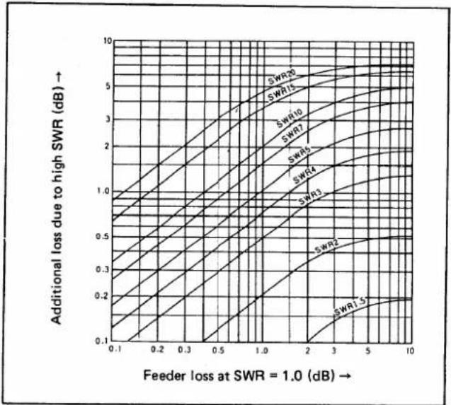
line
| Feeder loss at SWR = 1.0 (dB) | Additional loss due to high SWR (dB) | | ----------------------------- | ------------------------------------ | | 0.1 | 0.1 | | 0.2 | 0.2 | | 0.3 | 0.3 | | 0.5 | 0.5 | | 1.0 | 1.0 | | 2.0 | 2.0 | | 3.0 | 3.0 | | 5.0 | 4.0 | | 10.0 | 5.0 |● Loss from the coaxial cable
| LOSS (dB) per 10 m | |||||
| Coaxial cable\Frequency(MHz) | 3.5 | 7 | 14 | 21 | 28 |
| 3C-2V | 0.25 | 0.35 | 0.50 | 0.61 | 0.71 |
| 5C-2V | 0.16 | 0.23 | 0.32 | 0.39 | 0.46 |
| 7C-2V | 0.13 | 0.18 | 0.26 | 0.32 | 0.37 |
| 10C-2V | 0.11 | 0.15 | 0.22 | 0.28 | 0.31 |
| 5D-2V | 0.18 | 0.25 | 0.37 | 0.45 | 0.51 |
| 8D-2V | 0.12 | 0.17 | 0.23 | 0.30 | 0.35 |
| RG-58/U | 0.23 | 0.33 | 0.49 | 0.56 | 0.76 |
| RG-59/U | 0.21 | 0.30 | 0.43 | 0.51 | 0.59 |
| RG-8/U | 0.10 | 0.15 | 0.21 | 0.26 | 0.31 |
| RG-11/U | 0.12 | 0.18 | 0.26 | 0.32 | 0.38 |
This table shows attenuation per 10 m (30 ft) when used at SWR=1. The values given in this table are nominal, and may differ somewhat from actual values.
6-1 Troubleshooting
| PROBLEM | POSSIBLE CAUSE | SOLUTION | REF. |
| Power does not come on. | The exciter is turned OFF.Cable connection is not completed.[CIRCUIT BREAKER] is turned OFF.[OVERLOAD] on the linear amplifier lights. | Turn ON the exciter.Check the connection and connection cable pins.Check for the cause, then turn [CIRCUIT BREAKER] ON.Turn [POWER] OFF, wait until [OVERLOAD] goes out and ON again. | p. 5 |
| Output power is too low. | Reverse connection on the antenna input and output.ALC ADJ] is not adjusted properly.AMPLIFIER] is turned OFF.The protector circuit activates and the [PROTECT] indicator lights. | Be sure of the connection and connect again.Adjust [ALC ADJ] correctly.Turn ON the [AMPLIFIER] switch.Check any of the possible causes indicated under item 3 on p. 10. | p. 7p. 8p. 10 |
| Protection circuit activates during short periods of operation. | SWR of the antenna is more than 3 : 1.TUNER] is turned OFF.The linear amplifier is located in an area with bad air circulation.ALC ADJ] is adjusted to the wrong position. | Check the SWR.Adjust the antenna, if necessary.Turn ON the [TUNER] switch.Select a location with good air circulation.Adjust [ALC ADJ] to the correct position. | p. 9p. 5p. 8 |
6-2 CPU backup battery
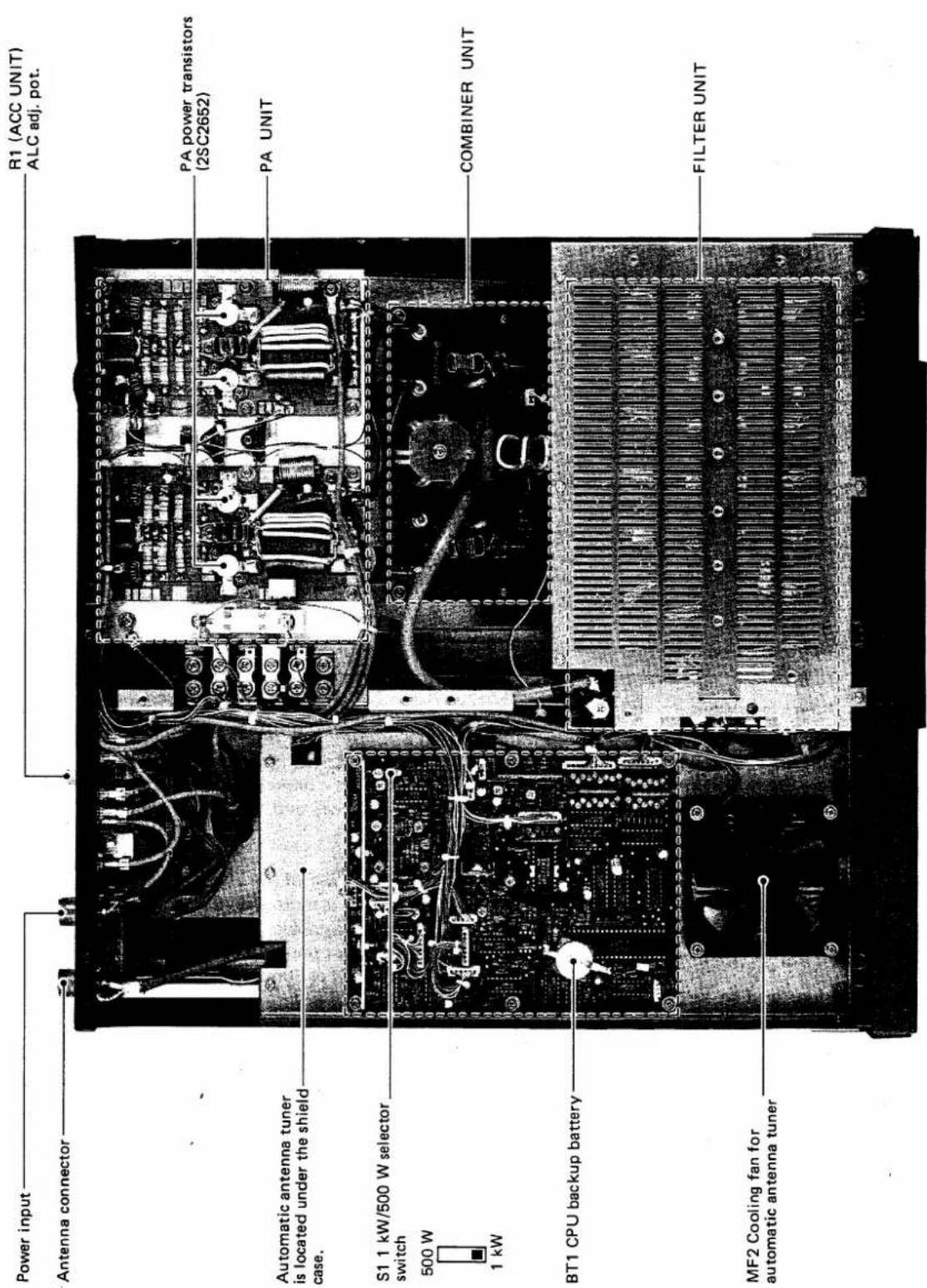
The IC-4KL linear amplifier has a CPU installed on the MAIN UNIT for memorizing previous matching conditions of the built-in antenna tuner. The matching condition is retained by a lithium backup battery. See p. 12 for the location.
When the backup battery is exhausted, the IC-4KL functions normally but the IC-4KL cannot retain previous matching conditions.
CAUTION: Backup battery replacement should be done by an authorized Icom Dealer or Service Center.
6-3 Cleaning
If the transceiver becomes dusty or dirty, wipe it clean with a dry, soft cloth. Avoid the use of strong cleaning agents such as benzine or alcohol as they may damage the surfaces of the transceiver.
8-1 Linear amplifier circuits
(1) Power splitter circuit
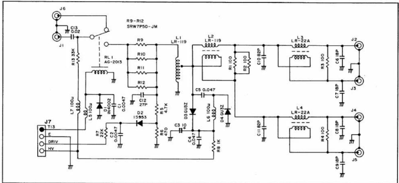
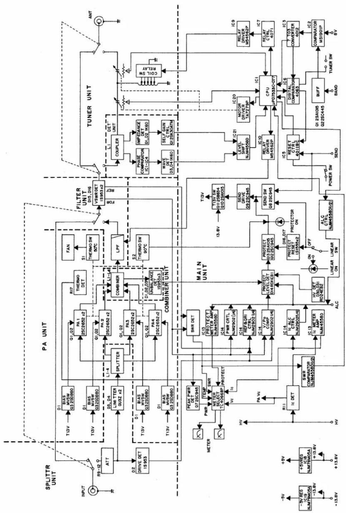
Output power from an exciter enters the SPLITTER UNIT. The power passes through the bypass/amplifier relay (RL1) and is then applied to an attenuator consisting of R9 \~ R12. The attenuator has 1 dB attenuation and functions as an impedance converter. L1 converts the input impedance of 50 Ω to a 12.5 Ω output impedance.
The attenuated power then passes through an input limiter consisting of D3 and D4. The input limiter is activated when the input RF power voltage exceeds 40 V. The power is split by 4 at L2 \~ L4 and is applied to the PA UNITS.
(2) Power amplifier circuit
One part of the split power is applied to the wide-band transformer (L1) where the input impedance is converted to 1/9. Impedance-converted power is power amplified at the PA UNITS up to 300 W. Power transistors Q1 and Q2 form a push-pull amplifier.
The power amplifier circuit has a negative feedback circuit that has frequency characteristics which obtain a flat response within 3 dB gain in all bands.
Amplified power is then applied to an impedance conversion transformer consisting of L4 and L5 for converting the output impedance to 50 Ω. Output power is then applied to the COMBINER UNIT with a 50 Ω load.
(3) Power combiner circuit
Output power from four PA UNITS is combined at L1 \~ L3 in the COMBINER UNIT to obtain output power of 1 kW. If the output power balance from four PA UNITS is broken, the unbalanced detector consisting of D1 \~ D3 outputs the negative voltage to the protector circuit via the "BAL" line.
Impedance at an output of L3 is converted to 50 Ω at L4. The output power passes through one of 7* low-pass filters in the FILTER UNIT and antenna tuner, and is then applied to the antenna connector.
* U.S.A. version : 6 low-pass filters
(4) Protector circuits (MAIN UNIT)
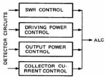
The IC-4KL has two protection systems. One system decreases an exciter's (transceiver's) driving power through the ALC line, and the other system bypasses the power amplifier.
- Output power of the linear amplifier decreases when:
- the SWR is more than 2:1.
- the driving power exceeds 100 W.
- the output power exceeds 1 kW.
- the collector current exceeds the limits.
●The linear amplifier is bypassed when:
- the power amplifier gain exceeds the limits.
- the power amplifier balance in the PA UNIT is broken.
- the heatsink temperature exceeds +90°C (+194°F).
●SWR CONTROL
Forward waves and reflected waves are detected at D15, D16 and L22 in the FILTER UNIT. The detected "REF" signal is applied to the drive power control circuit (IC14B) in the MAIN UNIT. When "REF" signal voltage increases, IC14B outputs signals of negative voltage to the exciter to control drive power.
●DRIVING POWER CONTROL
A portion of the attenuated input power from the input attenuator circuit is detected at D2 in the SPLITTER UNIT as the input power reference signal. The input power reference signal is applied to the MAIN UNIT via the "DRIV" line. The signal on the "DRIV" line is applied to the drive power control circuit (IC14B). When the drive power increases, IC14B outputs signals of negative voltage to the exciter to control the drive power.
●OUTPUT POWER CONTROL
Forward waves, "FOR" signal, detected at D15 in the FILTER UNIT are applied to the drive power control circuit (IC14A) in the MAIN UNIT. When the voltage of the "FOR" signal increases and exceeds the power set at R51 on the MAIN UNIT, IC14A outputs signals of negative voltage to control drive power.
•COLLECTOR CURRENT CONTROL
The "HV" line (40 V) passes through current detector resistor (R11) on the PA UNIT. The "HV" line and R11 passed voltage are applied to the MAIN UNIT as the "IC+" and "IC-" lines respectively. The "IC+" and "IC-" signals are applied to the current control circuit (IC13A). When the voltage on the "HV" line drops approximately 2.5 V at R11, IC13A outputs signals of negative voltage to the exciter to control drive power.
●POWER AMPLIFIER GAIN PROTECTION
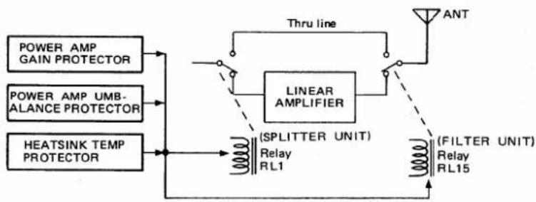
The forward wave detected at D15 in the FILTER UNIT is applied to the power amplifier gain comparator (IC14C). The attenuated and rectified driving power signal in the SPLITTER UNIT is also applied to IC14C. When the ratio of driving power and output power is more than approximately 3, IC14C outputs signals of negative voltage. The negative voltages turn OFF the bypass/amplifier relays (RL1, RL15) in the SPLITTER UNIT and FILTER UNIT through Q8 \~ Q13.
●POWER AMPLIFIER UNBALANCED PROTECTION
The power balance is detected at D1 \~ D3 in the COMBINER UNIT. When the power balance is broken, the "BAL" line is at a negative voltage level and is applied to D14 on the MAIN UNIT. The "BAL" line then turns OFF the bypass/amplifier relays (RL1, RL15) in the SPLITTER UNIT and FILTER UNIT through Q8 \~ Q13.
●HEATSINK TEMPERATURE PROTECTION
Two kinds of thermal sensors; +50°C (+122°F) and +90°C (+194°F) are installed on the heatsink. If the heatsink temperature rises to +50°C (+122°F) or above, the cooling fan is activated. If the temperature rises to +90°C (+194°F), the "TH" line becomes "LOW," turning OFF the bypass/amplifier relays (RL1, RL15) in the SPLITTER UNIT and FILTER UNIT through Q9 \~ Q11.
flowchart
graph TD
    A["SWR CONTROL"] --> C["ALC"]
    B["DRIVING POWER CONTROL"] --> C
    D["OUTPUT POWER CONTROL"] --> C
    E["COLLECTOR CURRENT CONTROL"] --> C
    C --> F["Output"]
    style A fill:#f9f,stroke:#333
    style B fill:#f9f,stroke:#333
    style D fill:#f9f,stroke:#333
    style E fill:#f9f,stroke:#333
flowchart
graph TD
    A["POWER AMP GAIN PROTECTOR"] --> B["THRU line"]
    C["POWER AMP UMB-ALANCE PROTECTOR"] --> B
    D["HEATSINK TEMP PROTECTOR"] --> E["(SPLITTER UNIT) Relay RL1"]
    B --> F["LINEAR AMPLIFIER"]
    E --> F
    F --> G["(FILTER UNIT) Relay RL15"]
    H["ANT"] --> G
8-2 Antenna tuner circuit
(1) Matching circuits
Variable capacitors C7 and C8 are connected to motors MF1 and MF2 respectively. Additional capacitors C1 and C2 are connected to C7 and C8 in parallel respectively when the linear amplifier operates in the 1.8 MHz band. C5 and C6 are connected to C7 and C8 in parallel (respectively) when the linear amplifier operates in the 3.5 MHz band. A tap of L10 is automatically grounded by the band-designed relays, RL7 \~ RL16. By using two separate motors, the IC-4KL obtains a faster overall tuning speed.
(2) Detector circuit
The antenna tuner has two detector circuits: an impedance component detector and a phase component detector.
Impedance components are picked up by L1 and detected by D1 and D2 on the DET UNIT. D2 outputs negative voltage and D1 outputs positive voltage. Output voltage of the impedance detector is added to the voltage output from D16 and D15. When antenna impedance is higher than 50 Ω, output voltage is positive; when lower than 50 Ω output voltage is negative.
Phase components are picked up by comparing the phases of the RF current and RF voltage. The RF current is detected by L1, R3 and R4. RF voltage is detected by C22 \~ C24. Both detector voltages are buffer amplified at IC1A and IC1B, and are then applied to the wave detector circuit consisting of IC2 \~ IC3.
flowchart
graph TD
    INPUT["INPUT"] --> ATT["ATT"]
    ATT --> D1["T13V"]
    D1 --> BIAS_MV5W_Q32SD860["BIAS_MV5W Q3 2SD860"]
    D1 --> BIAS_MV5W_Q32SD880["BIAS_MV5W Q3 2SD880"]
    ATT --> D2["DRIVE DET 1S 953"]
    D2 --> SPLITTER["SPLITTER"]
    SPLITTER --> PA1["PA 1 2SC2652 x2"]
    SPLITTER --> PA2["PA 2 2SC2652 x2"]
    SPLITTER --> PA3["PA 3 2SC2652 x2"]
    SPLITTER --> PA4["PA 4 2SC2652 x2"]
    PA1 --> Q1_Q2["Q1,Q2"]
    PA2 --> Q1_Q2
    PA3 --> Q1,Q2
    PA4 --> Q1,Q2
    Q1,Q2 --> COMBINER["COMBINER"]
    Q1,L4["L1-L4"] --> COMBINER
    COMBINER --> LPF["LPF"]
    LPF --> FILTER["FILTER UNIT D15,D16 VSWR DET 1S953x2"]
    FILTER --> FOR["FOR REF"]
    FILTER --> REF["REF"]
    TUNER[" TUNER UNIT "] --> ANT["ANT"]

    subgraph SPLITTR_UNIT
        ATT --> D2
        SPLITTR_UNIT --> D1
        SPLITTR_UNIT --> D3
        SPLITTR_UNIT --> D4
        SPLITTR_UNIT --> D5
        SPLITTR_UNIT --> D6
        SPLITTR_UNIT --> D7
        SPLITTR_UNIT --> D8
        SPLITTR_UNIT --> D9
        SPLITTR_UNIT --> D10
        SPLITTR_UNIT --> D11
        SPLITTR_UNIT --> D12
        SPLITTR_UNIT --> D13
        SPLITTR_UNIT --> D14
        SPLITTR_UNIT --> D15
        SPLITTR_UNIT --> D16
        SPLITTR_UNIT --> D17
        SPLITTR_UNIT --> D18
        SPLITTR_UNIT --> D19
        SPLITTR_UNIT --> D20
        SPLITTR_UNIT --> D21
        SPLITTR_UNIT --> D22
        SPLITTR_UNIT --> D23
        SPLITTR_UNIT --> D24
        SPLITTR_UNIT --> D25
        SPLITTR_UNIT --> D26
        SPLITTR_UNIT --> D27
        SPLITTR_UNIT --> D28
        SPLITTR_UNIT --> D29
        SPLITTR_UNIT --> D30
        SPLITTR_UNIT --> D31
        SPLITTR_UNIT --> D32
        SPLITTR_UNIT --> D33
        SPLITTR_UNIT --> D34
        SPLITTR_UNIT --> D35
        SPLITTR_UNIT --> D36
        SPLITTR_UNIT --> D37
        SPLITTR_UNIT --> D38
        SPLITTR_UNIT --> D39
        SPLITTR_UNIT --> D40
        SPLITTR_UNIT --> D41
        SPLITTR_UNIT --> D42
        SPLITTR_UNIT --> D43
        SPLITTR_UNIT --> D44
        SPLITTR_UNIT --> D45
        SPLITTR_UNIT --> D46
        SPLITTR_UNIT --> D47
        SPLITTR_UNIT --> D48
        SPLITTR_UNIT --> D49
        SPLITTR_UNIT --> D50
        SPLITTR_UNIT --> D51
        SPLITTR_UNIT --> D52
        SPLITTR_UNIT --> D53
        SPLITTR_UNIT --> D54
        SPLITTR_UNIT --> D55
        SPLITTR_UNIT --> D56
        SPLITTR_UNIT --> D57
        SPLITTR_UNIT --> D58
        SPLITTR_UNIT --> D59
        SPLITTR_UNIT --> D60
        SPLITTR_UNIT --> D61
        SPLITTR_UNIT --> D62
        SPLITTR_UNIT --> D63
        SPLITTR_UNIT --> D64
        SPLITTR_UNIT --> D65
        SPLITTR_UNIT --> D66
        SPLITTR_UNIT --> D67
        SPLITTR_UNIT --> D68
        SPLITTR_UNIT --> D69
        SPLITTR_UNIT --> D70
        SPLITTR_UNIT --> D71
        SPLITTR_UNIT --> D72
        SPLITTR_UNIT --> D73
        SPLITTR_UNIT --> D74
        SPLITTR_UNIT --> D75
        SPLITTR_UNIT --> D76
        SPLITTR_UNIT --> D77
        SPLITTR_UNIT --> D78
        SPLITTR_UNIT --> D79
        SPLITTR_UNIT --> D80
        SPLITTR_UNIT --> D81
        SPLITTR_UNIT --> D82
        SPLITTR_UNIT --> D83
        SPLITTR_UNIT --> D84
        SPLITTR_UNIT --> D85
        SPLITTR_UNIT --> D86
        SPLITTR_UNIT --> D87
        SPLITTR_UNIT --> D88
        SPLITTR_UNIT --> D89
        SPLITTR_UNIT --> D90
        SPLITTR_UNIT --> D91
        SPLITTR_UNIT --> D92
        SPLITTR_UNIT --> D93
        SPLITTR_UNIT --> D94
        SPLITTR_UNIT --> D95
        SPLITTR_UNIT --> D96
        SPLITTR_UNIT --> D97
        SPLITTR_UNIT --> D98
        SPLITTR_UNIT --> D99
        SPLITTR_UNIT --> EUTR_FLOWING_VOUTING_VOUTING_VOUTING_VOUTING_VOUTING_VOUTING_VOUTING_VOUTING_VOUTING_VOUTING_VOUTING_VOUTING_VOUTING_VOUTING_VOUTING_VOUTING_VOUTING_VOUTING_VOUTING_VOUTING_VOUTING_VOUTING_VOUTING_VOUTING_VOUTING_VOUTING_VOUTING_VOUTING_VOUTING_VOUTING_VOUTING_VOUTING_VOUTING_VOUTICOLLECTIVE_PARTMENTMENTMENTMENTMENTMENTMENTMENTMENTMENTMENTMENTMENTMENTMENTMENTMENTMENTMENTMENTMENTMENTMENTMENTMENTMENTMENTMENTMENTMENTMENTMENTMENTMENTMENTMENTMENTMENTMENTMENTMENTMENTMENTMENTMENTMENTMENTMENTMTENTRATE检测器控制信号检测器控制信号检测器控制信号检测器控制信号检测器控制信号检测器控制信号检测器控制信号检测器控制信号检测器控制信号检测器控制信号检测器控制信号检测器控制信号检测器控制信号检测器控制信号检测器控制信号检测器控制信号检测器控制信号检测器控制信号检测器控制信号检测器控制信号检测器控制信号检测器控制信号检测器控制信号检测器控制信号检测器控制信号检测器控制符号检测器控制信号检测器控制信号检测器控制信号检测器控制信号检测器控制信号检测器控制信号检测器控制信号检测器控制信号检测器控制信号检测器控制信号检测器控制信号检测器控制信号检测器控制信号检测器控制信号检测器控制信号检测器控制信号检测器控制信号检测器控制信号检测器控制信号检测器控制信号检测器控制信号检测器控制信号检测器控制信号检测器控制信号检测器控制号检测器控制信号检测器控制信号检测器控制信号检测器控制信号检测器控制信号检测器控制信号检测器控制信号检测器控制信号检测器控制信号检测器控制信号检测器控制信号检测器控制信号检测器控制信号检测器控制信号检测器控制信号检测器控制信号检测器控制信号检测器控制信号检测器控制信号检测器控制信号检测器控制信号检测器控制信号检测器控制信号检测器控制信号检测器控制型号检测器控制型号检测器控制型号检测器控制型号检测器控制型号检测器控制型号检测器控制型号检测器控制型号检测器控制型号检测器控制型号检测器控制型号检测器控制型号检测器控制型号检测器控制型号检测器控制型号检测器控制型号检测器控制型号检测器控制型号检测器控制型号检测器控制型号检测试验机检测试验机检测试验机检测试验机检测试验机检测试验机检测试验机检测试验机检测试验机检测试验机检测试验机检测试验机检测试验机检测试验机检测试验机检测试验机检测试验机检测试验机检测试验机检测试验机检测试验机检测试验机检测试验机检测试验机检测试验机检测试验电机检测试验电机检测试验电机检测试验电机检测试验电机检测试验电机检测试验电机检测试验电机检测试验电机检测试验电机检测试验电机检测试验电机检测试验电机检测试验电机检测试验电机检测试验电机检测试验电机检测试验电机检测试验电机检测试验电机检测试验电机检测试验电机检测试验电机检测试验电机检测试验电机检测试验电极管放大电路放大电路放大电路放大电路放大电路放大电路放大电路放大电路放大电路放大电路放大电路放大电路放大电路放大电路放大电路放大电路放大电路放大电路放大电路放大电路放大电路放大电路放大电路放大电路放大电路放大电路放大电路放大电路放大电路放大电路放大电路放大电路放大电路放大电路放大电路放大电路放大电路放大电路放大电路放大电路放大电路放大电路放大电路放大电路放大电路放大电路放大电路放大电路放大电路放大电路放大路放大电路放大路放大路放大路放大路放大路放大路放大路放大路放大路放大路放大路放大路放大路放大路放大路放大路放大路放大路放大路放大路放大路放大路放大路放大路放大路放大路放大路放大路放大路放大路放大路放大路放大路放大路放大路放大路放大路放大路放大路放大路放大路放大路放大路放大路放大路放大路放大路放大路放大路放大路放大路段放大路段放大路段放大路段放大路段放大路段放大路段放大路段放大路段放大路段放大路段放大路段放大路段放大路段放大路段放大路段放大路段放大路段放大路段放大路段放大路段放大路段放大路段放大路段放大路段放大路段放大路段放大路段放大路段放大路段放大路段放大路段放大路段放大路段放大路段放大路段放大路段放大路段放大路段放大路段放大路段放大路段放大路段放大路段放大路段放大路段放大路段放大路段放大路段放大路段放大段放线故障触发开关开关开关开关开关开关开关开关开关开关开关开关开关开关开关开关开关开关开关开关开关开关开关开关开关开关开关开关开关开关开关开关开关开关开关开关开关开关开关开关开关开关开关开关开关开关开关开关开关开关开关开关开关开关开关开关开关开关开关开关开关开关开关开关开关开关开关开关开关开关开关开关开关开关开关开关开关关断波转换模块TETERRALUSTRALUSTRALUSTRALUSTRALUSTRALUSTRALUSTRALUSTRALUSTRALUSTRALUSTRALUSTRALUSTRALUSTRALUSTRALUSTRALUSTRALUSTRALUSTRALUSTRALUSTRALUSTRALUSTRALUSTRALUSTRALUSTRALUSTRALUSTRALUSTRALUSTRALUSTRALUSTRALUSTRALUSTRULUSTRALUSTRALUSTRALUSTRALUSTRALUSTRALUSTRALUSTRALUSTRALUSTRALUSTRALUSTRALUSTRALUSTRALUSTRALUSTRALUSTRALUSTRALUSTRALUSTRALUSTRALUSTRALUSTRALUSTRALUSTRALUSTRALUSTRALUSTRALUSTRALUSTRALUSTRALUSTRALUSTRAL USTRALUSTRALUSTRALUSTRALUSTRALUSTRALUSTRALUSTRALUSTRALUSTRALUSTRALUSTRALUSTRALUSTRALUSTRALUSTRALUSTRALUSTRALUSTRALUSTRALUSTRALUSTRALUSTRALUSTRALUSTRALUSTRALUSTRALUSTRALUSTRALUSTRALUSTRALUSTRALUSTRALU STRAUCAMPROFECTIONFIGURECTIONFIGURECTIONFIGURECTIONFIGURECTIONFIGURECTIONFIGURECTIONFIGURECTIONFIGURECTIONFIGURECTIONFIGURECTIONFIGURECTIONFIGURECTIONFIGURECTIONFIGURECTIONFIGURECTIONFIGURECTIONFIGURECTIONFIGURECTIONFIGURECTIONFIGURECTIONFIGURECTIONFIGURECTIONFIGURECTIONFIGURECTIONFIGURECTIONFIGURECTIONFIGURECTIONFIGURECTIONFIGURECTIONFIGURECTIONFIGURECTIONFIGURECTIONFIGURECTIONFIGURERevisionFIGURERevisionFIGURERevisionFIGURERevisionFIGURERevisionFIGURERevisionFIGURERevisionFIGURERevisionFIGURERevisionFIGURERevisionFIGURERevisionFIGURERevisionFIGURERevisionFIGURERevisionFIGURERevisionFIGURERevisionFIGURERevisionFIGURERevisionFIGURERevisionFIGURERevisionFIGURERevisionFIGURERevisionFIGURERevisionFIGURERevisionFIGURERevisionFIGURERevisionFIGURERevisionFIGURERevisionFIGURERevisionFIGURERevisionFIGURERevisionFIGURERevisionFIGURERevisionFIGURERevisionSIGARETOPGNDAYEYNDAYEYNDAYEYNDAYEYNDAYEYNDAYEYNDAYEYNDAYEYNDAYEYNDAYEYNDAYEYNDAYEYNDAYEYNDAYEYNDAYEYNDAYEYNDAYEYNDAYEYNDAYEYNDAYEYNDAYEYNDAYEYNDAYEYNDAYEYNDAYEYNDAYEYEVDAYEYEVDAYEYEVDAYEYEVDAYEYEVDAYEYEVDAYEYEVDAYEYEVDAYEYEVDAYEYEVDAYEYEVDAYEYEVDAYEYEVDAYEYEVDAYEYEVDAYEYEVDAYEYEVDAYEYEVDAYEYEVDAYEYEVDAYEYEVDAYEYEVDAYEYEVDAYEYEVDAYEYEVDAYEYEVEVDAYEVEVDAYEVEVDAYEVEVDAYEVEVDAYEVEVDAYEVEVDAYEVEVDAYEVEVDAYEVEVDAYEVEVDAYEVEVDAYEVEVDAYEVEVDAYEVEVDAYEVEVDAYEVEVDAYEVEVDAYEVEVDAYEVEVDAYEVEVDAYEVEVDAYEVEVDAYEVEVDAYEVEVDAYEVEVDAYESDADATLDCDCDCDCDCDCDCDCDCDCDCDCDCDCDCDCDCDCDCDCDCDCDCDCDCDCDCDCDCDCDCDCDCDCDCDCDCDCDCDCDCDCDCDCDCDCDCDCDCDCDCDCDCDCDCDCDCDCDCDCDCDCDCDCDCDCDCDCDCDCDCDCDCDCDCDCDCDCDCDCDCDCDCDCDCDCDCDCDCDCDCDCDCDCDCDCDCDCDCDCDCCDCDCCDCCDCCDCCDCCDCCDCCDCCDCCDCCDCCDCCDCCDCCDCCDCCDCCDCCDCCDCCDCCDCCDCCDCCDCCDCCDCCDCCDCCDCCDCCDCCDCCDCCDCCDCCDCCDCCDCCDCCDCCDCCDCCDCCDCCDCCDCCDCCDCCDCCDCCCDDCDDCDDCDDCDDCDDCDDCDDCDDCDDCDDCDDCDDCDDCDDCDDCDDCDDCDDCDDCDDCDDCDDCDDCDDCDDCDDCDDCDDCDDCDDCDDCDDCDDCDDCDDCDDCDDCDDCDDCDDCDDCDDCDDCDDCDDCDDCDDCDDCDDCDDCAFFCDCAFFCDCAFFCDCAFFCDCAFFCDCAFFCDCAFFCDCAFFCDCAFFCDCAFFCDCAFFCDCAFFCDCAFFCDCAFFCDCAFFCDCAFFCDCAFFCDCAFFCDCAFFCDCAFFCDCAFFCDCAFFCDCAFFCDCAFFCDCAFFCDCAFFCDCAFFCDCAFFCDCAFFCDCAFFCDCAFFCDCAFFCDCAFFCDCAFFCDCATTCACCTCGTTTCACCTCGTTTCACCTCGTTTCACCTCGTTTCACCTCGTTTCACCTCGTTTCACCTCGTTTCACCTCGTTTCACCTCGTTTCACCTCGTTTCACCTCGTTTCACCTCGTTTCACCTCGTTTCACCTCGTTTCACCTCGTTTCACCTCGTTTCACCTCGTTTCACCTCGTTTCACCTCGTTTCACCTCGTTTCACCTCGTTCACCTCGTTCACCTCGTTCACCTCGTTCACCTCGTTCACCTCGTTCACCTCGTTCACCTCGTTCACCTCGTTCACCTCGTTCACCTCGTTCACCTCGTTCACCTCGTTCACCTCGTTCACCTCGTTCACCTCGTTCACCTCGTTCACCTCGTTCACCTCGTTCACCTCGTTCACCTCGTAGTTCAGTTCAGTTCAGTTCAGTTCAGTTCAGTTCAGTTCAGTTCAGTTCAGTTCAGTTCAGTTCAGTTCAGTTCAGTTCAGTTCAGTTCAGTTCAGTTCAGTTCAGTTCAGTTCAGTTCAGTTCAGTTCAGTTCAGTTCAGTTCAGTTCAGTTCAGTTCAGTTCAGTTCAGATTAATTAATTAATTAATTAATTAATTAATTAATTAATTAATTAATTAATTAATTAATTAATTAATTAATTAATTAATTAATTAATTAATTAATTAATTAATTAATTAATTAATTAATTAATTAATTAATTAATTAATTAATTAATTAATTAATTAATTAATTAATTAATTAATTAATTAATTAATTAATTAATTAATTAATATAATTAATTAATTAATTAATTAATTAATTAATTAATTAATTAATTAATTAATTAATTAATTAATTAATTAATTAATTAATTAATTAATTAATTAATTAATTAATTAATTAATTAATTAATTAATTAATTAATTAATTAATTAATTAATTAATTAATTAATTAATTAATTAATTAATTAATTAATTAATTAATTAATTAAT TAATTAATTAATTAATTAATTAATTAATTAATTAATTAATTAATTAATTAATTAATTAATTAATTAATTAATTAATTAAT TAATTAAT TAAT TAAT TAAT TAAT TAAT TAAT TAAT TAAT TAAT TAAT TAAT TAAT TAAT TAAT TAAT TAAT TAAT TAAT TAAT TAAT TAAT TAAT TAAT TAAT TAAT TA<nl>
To upgrade quality, some components may be subject to change without notice.
SPECIFICATIONS
GENERAL
• Frequency coverage :
1.800 \~ 1.999 MHz
3.500 \~ 3.999 MHz
7.000 \~ 7.300 MHz
10.100 \~ 10.150 MHz
14.000 \~ 14.350 MHz
18.068 \~ 18.168 MHz
21.000\~21.450 MHz
24.890 \~ 24.990 MHz*
28.000 \~ 29.700 MHz*
*The U.S.A. version does not include 24 \~ 28 MHz band range.
- Input impedance :
50 Ω (unbalanced)
• Duty cycle :
full duty continuously one hour with [TUNER] OFF (at 200 \~ 240 V AC, +25°C; +77°F)
• Power supply voltage :
100 \~ 120 V AC or 200 \~ 240 V AC ±10%
(Automatically switched)
• Usable temperature range :
-10^ +40^ (+14^ +104^)
- Dimensions :
Remote controller 200(W) x 149(H) x 341(D) mm
7.9(W) × 5.9(H) × 13.4(D) in
Linear amplifier 425(W) × 297(H) × 458.5(D) mm
16.7(W) × 11.7(H) × 18.1(D) in
(projections not included)
- Weight :
Remote controller 2.7 kg (6.0 lb)
Linear amplifier 36.0 kg (79.4 lb)
■ LINEAR AMPLIFIER
- Output power :
| MODE | INPUT AC VOLTAGE | |
| 200~240 V AC | 100~120 V AC | |
| CW, RTTY | 1 kW* | 500 W |
| SSB | 1 kW PEP* | 500 W PEP |
*24.5 and 28 MHz bands : 800 W (PEP)
- Driving power :
100 W max.
• Final PA efficiency :
50% or more (at 1 kW output power)
- Spurious emissions :
Less than -60 dB
■ ANTENNA TUNER
• Output matching range :
16.7 Ω \~ 150 Ω
(when the TUNER switch is ON)
• Auto tuning accuracy :
VSWR less than 1.2 : 1
- Insertion loss :
Less than 0.5 dB (after tuning)
The antenna tuner might not match an antenna at either edge of the 1.8 MHz band.
All stated specifications are subject to change without notice or obligation.
Count on us!
natural_image
Pure black background with a thin white horizontal line at the bottom (no text or symbols)- FOREWORD
- IMPORTANT
- PRECAUTIONS
- TABLE OF CONTENTS
- UNPACKING
- kW OUTPUT AT FULL DUTY CYCLE
- SEPARATED CONTROLLER AND AMPLIFIER
- FULLY AUTOMATIC, HIGH-SPEED ANTENNA TUNER
- FULL BREAK-IN OPERATION
- COMPLETE PROTECTION CIRCUITS
- OTHER OUTSTANDING FEATURES
- 2-1 Linear amplifier
- OVERLOAD INDICATOR [OVERLOAD]
- POWER INDICATOR [POWER]
- CIRCUIT BREAKER
- ALC ADJUSTMENT CONTROL [ALC ADJ]
- ACC SOCKETS [ACC]
- POWER INPUT CONNECTOR [INPUT]
- ANTENNA CONNECTOR [ANT]
- GROUND TERMINAL [GND]
- REMOTE CONTROL SOCKET
- AC POWER CABLE
- PANEL DESCRIPTION
- 2-2 Remote controller
- METER 1 SWITCHES [METER 1]
- TRANSMIT INDICATOR [TRANSMIT]
- PROTECTION/TEMPERATURE SELECTOR SWITCH [PRO/TEMP]
- REMOTE CONTROL SOCKET
- 3-1 Unpacking
- 3-2 Setting location
- 3-3 AC power cable connection
- 3-4 Antenna system
- 3-5 Ground system
- - AC power cable connection
- - PL-259 connector installation
- 3-6 Handle installation
- 3-7 ACC socket information
- 5-1 Cautions
- 5-2 Presettings
- CAUTION: Final power transistors may be damaged if the ALC control is set at a wrong position.
- OPERATION
- 5-4 Operation
- CAUTION:
- Tech Talk from Icom
- How does the IC-4KL antenna tuner advance?
- 5-5 Protector circuit information
- 5-6 Antenna tuner information
- 6-2 CPU backup battery
- 6-3 Cleaning
- 8-1 Linear amplifier circuits
- Power splitter circuit
- Power amplifier circuit
- Power combiner circuit
- Protector circuits (MAIN UNIT)
- ●SWR CONTROL
- ●DRIVING POWER CONTROL
- ●OUTPUT POWER CONTROL
- •COLLECTOR CURRENT CONTROL
- ●POWER AMPLIFIER GAIN PROTECTION
- ●POWER AMPLIFIER UNBALANCED PROTECTION
- ●HEATSINK TEMPERATURE PROTECTION
- 8-2 Antenna tuner circuit
- Matching circuits
- Detector circuit
- SPECIFICATIONS
- GENERAL
- ■ LINEAR AMPLIFIER
- ■ ANTENNA TUNER
Marke : ICOM
Modell : IC-4KL
Kategorie : Empfänger