ICOM IC-701PS - Empfänger

IC-701PS - Empfänger ICOM - Kostenlose Bedienungsanleitung

Finden Sie kostenlos die Bedienungsanleitung des Geräts IC-701PS ICOM als PDF.

📄 3 Seiten Deutsch DE Herunterladen 💬 KI-Frage 10 Fragen ⚙️ Technik
Notice ICOM IC-701PS - page 1
Waehlen Sie Ihre Sprache und Ihre E-Mail-Adresse: wir senden Ihnen eine speziell uebersetzte Version.
ProdukttypNetzteil für den ICOM IC-701
Eingangsspannung117/230 V AC (50/60 Hz), ±10% Toleranz
Ausgangsspannung13,8 V DC (bei 20 A Last)
Maximaler Laststrom20 A (10 Min. Ein / 10 Min. Aus, 50% Einschaltdauer)
Leistungsaufnahme360 VA (bei 20 A Last)
Abmessungen (H × B × T)110 × 180 × 260 mm
Gewichtca. 8 kg
Eingebauter Lautsprecher125 × 77 mm, 8 Ohm, 2 W Nennleistung, 4 W maximal
SchalterHauptschalter (Netzschalter); Ein/Aus wird über den IC-701 gesteuert
Sicherung5 A (bei 117 V) / 3 A (bei 230 V), im Sicherungshalter
AnschlüsseAC-Eingang, DC-Ausgangsstecker, Lautsprecher-Eingangsbuchse (SPK INPUT), Lüfteranschluss (FAN)
ErdungsklemmeMasseanschluss zur Vermeidung von Stromschlägen
FernsteuerungEin/Aus wird über den Netzschalter des IC-701 gesteuert (Relais)
KühlungLüfteranschluss (12 V, ca. 100 mA) für optionale Aktivkühlung bei Dauerbetrieb
ZubehörAC-Netzkabel, Ersatzsicherungen (2 St.), Lautsprecherkabel
Empfohlene VerwendungNur für IC-701; nicht für andere Geräte geeignet

Häufig gestellte Fragen - IC-701PS ICOM

Wie schalte ich das IC-701PS ein?
Das Netzteil wird über den Netzschalter des IC-701 ein- und ausgeschaltet. Das IC-701PS besitzt keinen eigenen Netzschalter, aber einen Hauptschalter (Main Switch), der bei längerem Nichtgebrauch ausgeschaltet werden sollte.
Welche Spannung liefert das Netzteil?
Die Ausgangsspannung beträgt 13,8 V DC bei einem maximalen Laststrom von 20 A (50% Einschaltdauer).
Kann das Netzteil auch für andere Geräte verwendet werden?
Nein, es wird empfohlen, das Netzteil nur mit dem IC-701 zu verwenden, da es speziell dafür ausgelegt ist.
Welche Sicherung benötigt das IC-701PS?
Bei 117 V Netzspannung eine 5 A Sicherung, bei 230 V eine 3 A Sicherung. Ersatzsicherungen liegen bei. Zum Öffnen des Sicherungshalters einen Kreuzschlitzschraubendreher verwenden.
Wie schließe ich den internen Lautsprecher an?
Verbinden Sie die SPK INPUT Buchse auf der Rückseite des Netzteils mit der EXT SPK Buchse des IC-701 über das mitgelieferte Lautsprecherkabel. Der Lautsprecher hat eine Impedanz von 8 Ohm und eine Nennbelastbarkeit von 2 Watt.
Muss die Erdungsklemme angeschlossen werden?
Ja, schließen Sie die GND Klemme mit einem möglichst kurzen Kabel an Erde an, um einen Schutz vor Stromschlägen zu gewährleisten.
Kann ich einen Lüfter anschließen?
Ja, an der FAN Buchse liegt 12 V mit ca. 100 mA an. Für Dauerbetrieb (z.B. RTTY) wird ein optionaler Lüfter empfohlen.
Was tun, wenn die Sicherung durchbrennt?
Überprüfen Sie zuerst die Ursache (z.B. Kurzschluss oder Überlast) und ersetzen Sie die Sicherung durch eine des korrekten Typs (5 A bei 117 V, 3 A bei 230 V). Benutzen Sie keinen höheren Wert.
Welche Maße und welches Gewicht hat das Netzteil?
Die Abmessungen betragen 110 × 180 × 260 mm (H × B × T), das Gewicht liegt bei ca. 8 kg.
Kann das IC-701PS auch mit 100 V Netzspannung betrieben werden?
Der Schaltplan zeigt einen Anschluss für 100 V auf der Primärseite des Transformators, aber die Spezifikation gibt 117/230 V ±10% an. Eine Verwendung mit 100 V ist nicht vorgesehen.

Benutzerfragen zu IC-701PS ICOM

0 Frage zu diesem Gerät. Beantworten Sie die, die Sie kennen, oder stellen Sie Ihre eigene.

Eine neue Frage zu diesem Gerät stellen

Die E-Mail bleibt privat: Sie dient nur dazu, Sie zu benachrichtigen, wenn jemand auf Ihre Frage antwortet.

Noch keine Fragen. Stellen Sie die erste.

Laden Sie die Anleitung für Ihr Empfänger kostenlos im PDF-Format! Finden Sie Ihr Handbuch IC-701PS - ICOM und nehmen Sie Ihr elektronisches Gerät wieder in die Hand. Auf dieser Seite sind alle Dokumente veröffentlicht, die für die Verwendung Ihres Geräts notwendig sind. IC-701PS von der Marke ICOM.

BEDIENUNGSANLEITUNG IC-701PS ICOM

IC-701PS

AC POWER SUPPLY

INSTRUCTION MANUAL
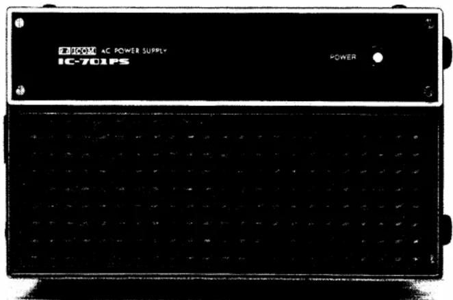
T-100M AC POWER SUPPLY IC-701PS POWER

Thank you for choosing the IC-701PS. This unit is an AC Power Supply for the IC-701, ICOM's Digital All Solid State HF Transceiver.

SPECIFICATIONS

• Number of Semi-Silicon diode 3
conductors: LED 1 • Input Voltage 117/230V AC (50/60 Hz)
- Allowable voltage fluctuation: ±10% of input voltage (suitable line voltage)
- Input Capacity: 360VA (at 20A load)
• Output Voltage: DC13.8V (at 20A load)
• Max. Load Current: 20A (10 minutes ON/10 minutes OFF 50% duty cycle)
- Polarization: Negative ground
• Internal Speaker: 125 x 77 mm
2 watt nominal input 4 watt maximum
• Dimensions: 110 (H) × 180 (W) × 260 (D) mm
• Weight: Approximately 8 kg
• Accessories included: AC power cord 1
Spare fuse 2
Speaker cord 1

(suitable voltage):

BEFORE USE

This is an AC power supply for the IC-701 and is designed to be turned ON and OFF with the power switch on your IC-701; this unit does not have a separate power switch.

As this unit has 20A maximum capacity at 13.8V DC, it is recommended that you do not use this unit with other than the IC-701, even for experimental purposes.

HOW TO USE

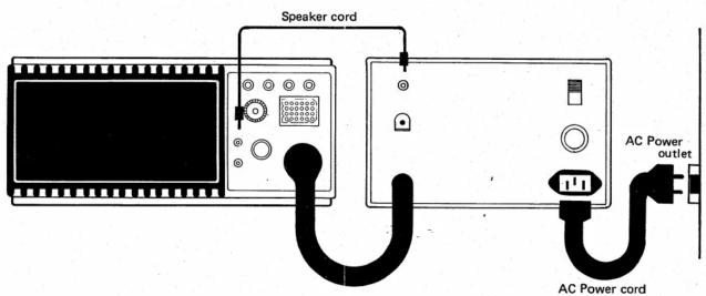
Connect the DC output plug of this unit to the IC-701 power connector securely, as shown in the figure at right. At this time, make sure that

(1) the power switch on the IC-701 is OFF,

(2) the T/R switch is at the RECEIVE position, and (3) no microphone is connected.

Connect the AC power cord to the AC power connector on the rear panel of the IC-701PS. Connect the AC power cord plug in the power outlet. At this time, the remote control relay in this unit will be at the standby position. By turning the IC-701 power switch ON, this unit will be turned ON and the power display LED illuminated. For further operating information, see the instruction manual for the IC-701.
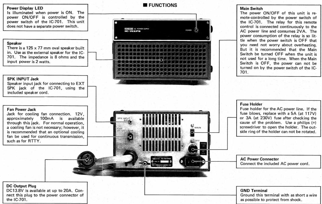
■ FUNCTIONS Power Display LED Is illuminated when power is ON. The power ON/OFF is controlled by the power switch of the IC-701. This unit does not have a separate power switch. Speaker There is a 125 x 77 mm oval speaker built in. Use as the external speaker for the IC-701. The impedance is 8 ohms and the input power is 2 watts. SPK INPUT Jack Speaker input jack for connecting to EXT SPK jack of the IC-701, using the included speaker cord. Fan Power Jack Jack for cooling fan connection. 12V, approximately 100mA is available through this jack. For normal operation, a cooling fan is not necessary; however, it is recommended that an optional cooling fan be used for continuous transmission, such as for RTTY. DC Output Plug DC13.8V is available at up to 20A. Connect this plug to the power connector of the IC-701. Main Switch The power ON/OFF of this unit is remote-controlled by the power switch of the IC-701. The relay for this remote control is connected continuously to the AC power line and consumes 2VA. The power consumption of the relay is so little when the power switch is OFF that you need not worry about overheating. But it is recommended that the Main Switch be turned OFF when the unit is not used for a long time. When the Main Switch is OFF, the power can not be turned on by the power switch of the IC-701. Fuse Holder Fuse holder for the AC power line. If the fuse blows, replace with a 5A (at 117V) or 3A (at 230V) fuse after checking the cause of the problem. Use a philips (+) screwdriver to open the holder. The outside ring of the holder can not be rotated. AC Power Connector Connect the included AC power cord. GND Terminal Ground this terminal with as short a wire as possible to protect from shock.

Speaker cord AC Power outlet AC Power cord

● HOW TO USE THE INTERNAL SPEAKER

Use the included speaker cord to connect the SPK INPUT jack on the rear panel of the IC-701PS and the EXT SPK jack on the rear panel of the IC-701.

The impedance and nominal input power of the speaker in this unit are 8 ohms and 2 watts, respectively, and this speaker can be used with any transceiver with these specifications. This speaker is designed for communication purposes and is not suitable for Hi-Fi use.
ICOM IC-701PS - ● HOW TO USE THE INTERNAL SPEAKER - 1

ICOM

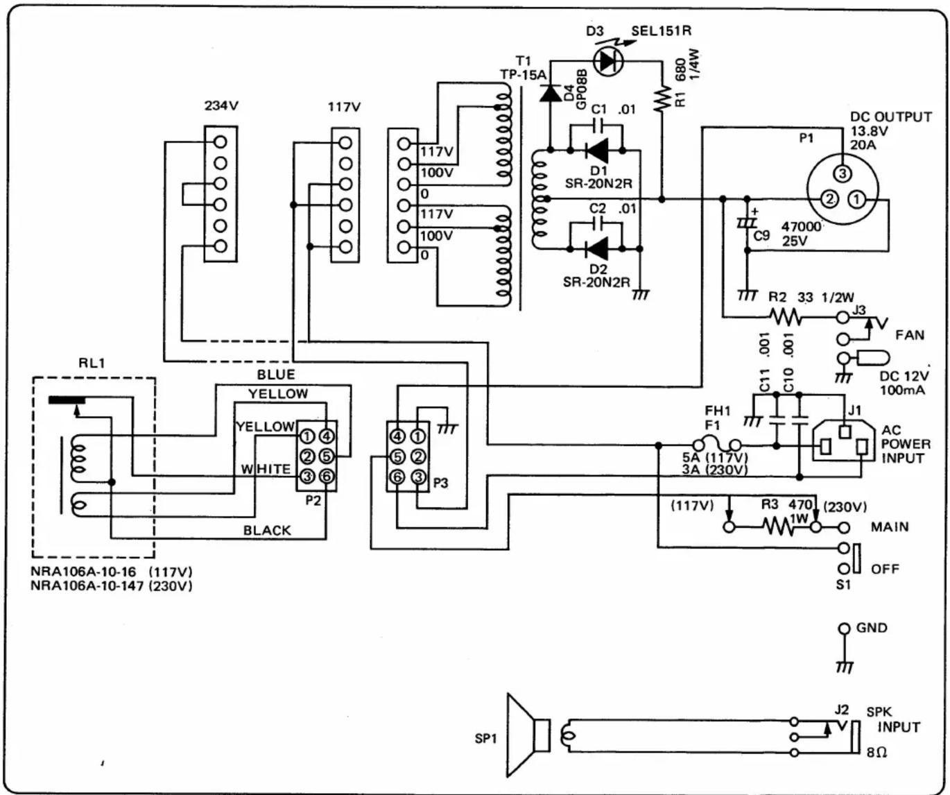
■ IC-701PS SCHEMATIC DIAGRAM
234V 117V 117V 100V 0 117V 100V 0 T1 TP-15A D4 GPOBB 680 1/4W R1 D3 SEL151R C1 .01 D1 SR-20N2R C2 .01 D2 SR-20N2R P1 DC OUTPUT 13.8V 20A + C9 47000 25V R2 33 1/2W J3 FAN J1 AC POWER INPUT C11 .001 C10 .001 C11 5A (117V) 3A (230V) FH1 F1 (117V) R3 470 (230V) MAIN OFF S1 GND RL1 BLUE YELLOW YELLOW ①④ WHITE ②⑤ ③⑥ P2 BLACK NRA106A-10-16 (117V) NRA106A-10-147 (230V) SP1 J2 SPK INPUT 8Ω

Inhaltsverzeichnis Klicken Sie auf einen Titel, um darauf zuzugreifen
Handbuch-Assistent
Angetrieben von Anthropic
Warten auf Ihre Nachricht
Produktinformationen

Marke : ICOM

Modell : IC-701PS

Kategorie : Empfänger