
IC-900A - Empfänger ICOM - Kostenlose Bedienungsanleitung
Finden Sie kostenlos die Bedienungsanleitung des Geräts IC-900A ICOM als PDF.


| Produkttyp | SUPER MULTI-BANDER SYSTEM Empfänger/Transceiver |
| Marke | ICOM |
| Modell | IC-900A / IC-900E |
| Frequenzbereiche (mit optionalen Band-Einheiten) | 28–30 MHz (10 W), 50–54 MHz (10 W), 138–174 MHz (25/45 W), 216–236 MHz (25 W), 430–450 MHz (25 W), 1240–1300 MHz (10 W) |
| Anzahl Band-Einheiten | Bis zu 6 gleichzeitig |
| Betriebsart | FM |
| Duplexbetrieb | Voll Duplex auf allen Bändern |
| Speicherkanäle | 10 pro Band-Einheit, insgesamt bis zu 60 |
| Abstimmschritte | IC-900A: 5/10/15/20/25 kHz; IC-900E: 12,5/25 kHz |
| RIT/VXO | Feinabstimmung ±7 kHz (nur mit UX-129 1200-MHz-Band-Einheit) |
| Scan-Funktionen | Programmierter Scan, Memory-Scan, Überspringen von Kanälen |
| Rufkanal | Programmierbarer Rufkanal pro Band |
| Fernbedienung | Separates Multifunktions-Fernbedienteil mit Display |
| Verbindung | Lichtwellenleiter zwischen Interface A und Interface B |
| Stromversorgung | 12 V Gleichstrom (5 A Sicherung für Interface-A, 15 A für Interface-B) |
| Optionale Einheiten | UT-28 Digital-Code-Squelch, UT-29 Ton-Squelch, CF-11 Lüfter, MB-21 Halterung |
| Mikrofon | HM-12, HM-14 oder HM-15 (je nach Version) |
| Lautsprecher | SP-8 (im Lieferumfang), optional SP-10 |
| Betriebstemperatur | Nicht explizit angegeben, aber vor direkter Sonne und Hitze schützen |
| Reinigung | Milde Seifenlösung, keine starken Chemikalien |
Häufig gestellte Fragen - IC-900A ICOM
Benutzerfragen zu IC-900A ICOM
0 Frage zu diesem Gerät. Beantworten Sie die, die Sie kennen, oder stellen Sie Ihre eigene.
Eine neue Frage zu diesem Gerät stellen
Laden Sie die Anleitung für Ihr Empfänger kostenlos im PDF-Format! Finden Sie Ihr Handbuch IC-900A - ICOM und nehmen Sie Ihr elektronisches Gerät wieder in die Hand. Auf dieser Seite sind alle Dokumente veröffentlicht, die für die Verwendung Ihres Geräts notwendig sind. IC-900A von der Marke ICOM.
BEDIENUNGSANLEITUNG IC-900A ICOM
INSTRUCTION MANUAL
SUPER MULTI-BANDER
SYSTEM
IC-900A
IC-900E
FOREWORD
ICOM has been listening carefully to the many ideas of Amateur Radio enthusiasts worldwide, and the result, built with the very latest in optical technological know how, is an engineering marvel: ICOM's advanced new IC-900A/E FM SUPER MULTI-BANDER SYSTEM transceiver.
The IC-900A/E is a multi-bander system transceiver that allows the mobile user to completely customize in creating a communications system with a distinctly personal touch. Up to 6 separate BAND UNITS can be installed and used with the IC-900A/E, systematically upgrading the degree of transceiver versatility with every new BAND UNIT added.
The IC-900A/E is equipped with a superb assortment of deluxe ICOM features such as all VHF/UHF band operation capability (above 28MHz), a separate multi-function REMOTE CONTROLLER, durable and advanced optical fiber connections, simultaneous dual band receive and full duplex capability, and more.
To fully appreciate and understand the capabilities of your new IC-900A/E FM SUPER MULTI-BANDER SYSTEM, please study this instruction manual thoroughly prior to operation. Also feel free to contact your nearest authorized ICOM Dealer or Service Center if you require assistance or information regarding the operation of your new IC-900A/E.
1. FEATURES
SELECTABLE ONE TO SIX BAND OPERATION
A total of up to six optional BAND UNITS can be installed in the IC-900A/E for instant access to a wide range of frequencies from the 28MHz HF band to the 1200MHz UHF band. And only a small and light REMOTE CONTROLLER is necessary for control of all these bands.
OPTICAL FIBER CABLE
A durable and flexible optical fiber cable is used between the INTERFACE UNIT-A and the INTERFACE UNIT-B to ensure reliable, interference-free communications.
FULL DUPLEX CAPABILITY
The IC-900A/E has independent, full duplex capability on all bands, providing simultaneous receive and transmit operation on separate bands. Monitoring the bands is simple too because of the convenient FUNCTION DISPLAY on the REMOTE CONTROLLER which shows two separate operating frequencies simultaneously.
A VARIETY OF ADVANCED FUNCTIONS AVAILABLE
MEMORY CHANNEL CAPABILITY
The IC-900A/E MULTI-BANDER SYSTEM transceiver is equipped with 10 fully programmable memory channels in each BAND UNIT. The system can therefore store information in up to 60 different memory channels. (Each BAND UNIT can memorize all frequencies which the particular BAND UNIT covers).
5 SEPARATE USER-PROGRAMMED TUNING STEPS
Tuning steps can be selected in 5kHz, 10kHz, 15kHz, 20kHz and 25kHz steps in the IC-900A version and in 12.5kHz and 25kHz steps in the IC-900E version.
OPTIONAL UNIT OPERATIONS
Either the UT-28 DIGITAL CODE SQUELCH UNIT or the UT-29 TONE SQUELCH UNIT can be used to ensure clear, interference-free communications from other stations using the same frequency.
TABLE OF CONTENTS
-
FEATURES.... 1
-
CONSTRUCTION 2
-
UNPACKING 3
-
INSTALLATIONS.... 5
4-1 UNIT INSTALLATIONS.... 5
4-2 UNIT-CONNECTIONS 6
4-3 OTHERS....11
- PRE-OPERATION.... 14
- 6. BASIC OPERATIONS.... 15
6-1 RECEIVING 15
6-2 TRANSMITTING 17
- CONTROL FUNCTIONS.... 19
7-1 REMOTE CONTROLLER.... 20
7-2 FUNCTION DISPLAY 22
7-3 MICROPHONE 25
- FUNCTION OPERATIONS 26
8-1 MEMORY OPERATIONS 26
8-2 SCAN OPERATIONS 27
8-3 CALL CHANNEL OPERATIONS.... 28
8-4 BEEP TONE ON AND OFF.... 29
- SET MODE 30
9-1 SET MODE CONSTRUCTION.... 30
9-2 TUNING STEP (A) 31
9-3 TUNING STEP (B) 31
9-4 OFFSET WRITE 31
9-5 SUBAUDIBLE TONE FREQUENCY 32
9-6 SCAN EDGES 32
9-7 BAND UNIT 32
- OPTIONAL SQUELCH UNIT 33
10-1 UT-28 AND UT-29 INSTALLATION.... 33
10-2 UT-28 AND UT-29 SELECTION.... 34
10-3 UT-28 OPERATION 35
10-4 UT-29 OPERATION.... 37
-
MAINTENANCE.... 38
-
BLOCK DIAGRAM 39
-
SPECIFICATIONS 40
2. CONSTRUCTION
CONSTRUCTION OF THE IC-900 MULTI-BANDER SYSTEM
The IC-900A/E MULTI-BANDER SYSTEM consists of a REMOTE CONTROLLER, INTERFACE UNIT-A, INTERFACE UNIT-B, and a series of specially designed, attachable BAND UNITS for upgrading your transceiver system.
| MODEL | - FREQUENCY RANGE | OUTPUT POWER | SELECTABLE TUNING STEP | |
| HIGH | LOW | |||
| UX-19A/E | 28.00 ~ 30.00MHz | 10W | 1W | 5, 10, 15, 20, 25kHz |
| UX-59A | 50.00 ~ 54.00MHz | 10W | 1W | 5, 10, 15, 20, 25kHz |
| UX-29A (USA, Asia) | *1 138.00 ~ 174.00MHz (Receive)140.10 ~ 150.00MHz (Transmit) | 25W | 5W | 5, 10, 15, 20, 25kHz |
| UX-29A (Australia) | 144.00 ~ 148.00MHz | 25W | 5W | 5, 10, 15, 20, 25kHz |
| UX-29E (Europe) | 144.00 ~ 146.00MHz | 25W | 5W | 12.5, 25kHz |
| UX-29E (Italy) | *1 140.00 ~ 150.00MHz | 25W | 5W | 12.5, 25kHz |
| UX-29H (USA, Asia) | *1 138.00 ~ 174.00MHz (Receive)140.10 ~ 150.00MHz (Transmit) | 45W | 5W | 5, 10, 15, 20, 25kHz |
| UX-29H (Australia) | 144.00 ~ 148.00MHz | 45W | 5W | 5, 10, 15, 20, 25kHz |
| UX-29H (Europe) | 144.00 ~ 146.00MHz | 45W | 5W | 12.5, 25kHz |
| UX-29H (Italy) | *1 140.00 ~ 150.00MHz | 45W | 5W | 12.5, 25kHz |
| UX-39A | *2 216.00 ~ 236.00MHz (Receive)220.00 ~ 225.00MHz (Transmit) | 25W | 5W | 5, 10, 15, 20, 25kHz |
| UX-49A (USA) | 440.00 ~ 450.00MHz | 25W | 5W | 5, 10, 15, 20, 25kHz |
| UX-49A (Australia, Asia) | 430.00 ~ 440.00MHz | 25W | 5W | 5, 10, 15, 20, 25kHz |
| UX-49E | 430.00 ~ 440.00MHz | 25W | 5W | 12.5, 25kHz |
| UX-129A | 1240.00 ~ 1300.00MHz | 10W | 1W | 10, 20kHz |
| UX-129E | 1240.00 ~ 1300.00MHz | 10W | 1W | 12.5, 25kHz |
Guaranteed frequency range: *1 144.00 \~ 148.00MHz *2 220.00 \~ 225.00MHz
MULTI-BANDER SYSTEM BLOCK DIAGRAM
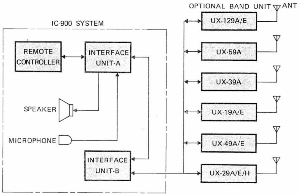
flowchart
graph TD
    A["REMOTE CONTROLLER"] --> B["INTERFACE UNIT-A"]
    C["SPEAKER"] --> B
    D["MICROPHONE"] --> B
    B --> E["INTERFACE UNIT-B"]
    E --> F["OPTIONAL BAND UNIT ANT"]
    F --> G["UX-129A/E"]
    F --> H["UX-59A"]
    F --> I["UX-39A"]
    F --> J["UX-19A/E"]
    F --> K["UX-49A/E"]
    F --> L["UX-29A/E/H"]
3. UNPACKING
The following accessories come with the IC-900A/E. Check the accessories after removing them from the carton. Store unused accessories for future use as you build up your IC-900 SYSTEM.
POWER SOURCE ACCESSORIES
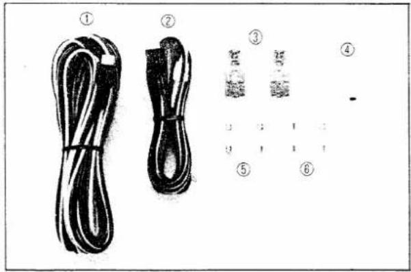
① OPC-170 POWER CABLE 1
② OPG-095 POWER CABLE 1
③ Cable separator sockets 2
④ Cable lugs 2
⑤ Fuses (15A) 2
⑥ Fuses (5A) 2
●INTERFACE UNIT-A ACCESSORIES
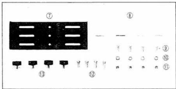
⑦ Mounting bracket (A) 1
⑧ Double-sided tape 4
⑨ Mounting screws (M4 x 12) 4
⑩ Flat washers (M4) 4
⑪ Nuts (M4) 4
⑫ Self-tapping mounting screws (A0 4 x 16) ..... 4
⑬ Mounting bracket knobs 4
- INTERFACE UNIT-B ACCESSORIES
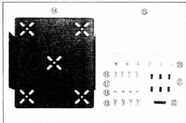
⑭ Mounting bracket (B)....1
⑮ Sponges. 2
⑯ Mounting screws (M4 x 12)....4
⑰ Flat washers (M4) 4
⑱ Nuts (M4) 4
⑲ Self-tapping mounting screws (A0 4 x 16) ..... 4
⑳ Unit mounting screws (M4 x 8) ..... 6
② Rubber bushings (S) 6
② Rubber bushing (L) 1
●SUPPORT BRACKET
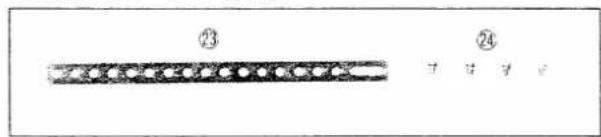
②3 Support bracket 1
②4 Set screws (A) (4 x 8) 4
●OPTICAL FIBER CABLE
natural_image
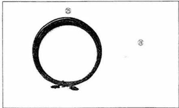
Simple line drawing of a circular object with two small protrusions, no text or symbols present②5 OPC-172 OPTICAL FIBER CABLE ..... 1
②6 Cable clamps 2
●REMOTE CONTROLLER ACCESSORIES
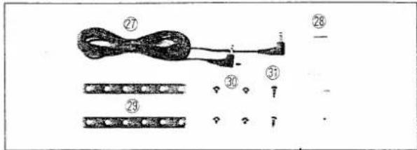
⑳ OPC-177 CONTROLLER CABLE ..... 1
⑳ Double-sided tapes 2
⑲ Controller support brackets.... 2
③0 Mounting screws (Button head) 4
③1 Self-tapping mounting screws (A0 3 x 8) ..... 2
MICROPHONE
natural_image
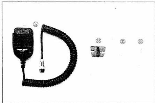
Product diagram showing a black connector with coiled cable and three labeled parts (③2, ③3, ③4, ③5) without any text or symbols.③2 *Microphone 1
③3 Microphone hanger 1
③4 Microphone connector support 1
③5 Self-tapping screw (A0 4 x 10) ..... 1
*HM-12 (IC-900A Australia, Asia)
HM-14 (IC-900A USA)
HM-15 (IC-900E)
●SPEAKER
natural_image
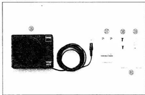
Exterior view of a black electronic device with a cable and connector, alongside a grid of numbered labels (36–40) for identification.③6 Speaker (SP-8) 1
③7 Mounting clip 1
38 Self-tapping screws (B0 3 x 8) ..... 2
⑲ External speaker plug. 1
④ Double-sided tape 2
●BAND UNIT UNPACKING
natural_image
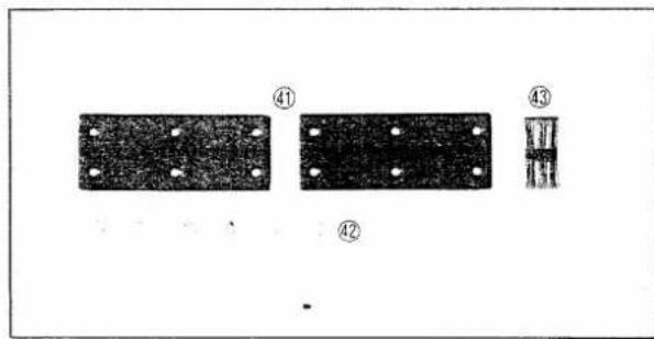
Three black rectangular panels with white holes, labeled ④1, ④2, and ④3, showing different surface textures (no text or symbols beyond labels)④ Mounting brackets 2
④2 Mounting screws (M4 x 8) 6
④3 OPC-179 JOINT CABLE 1
4. INSTALLATIONS
4 - 1 UNIT INSTALLATIONS
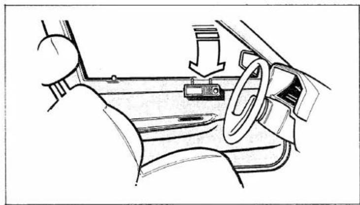
• Near the driver's position
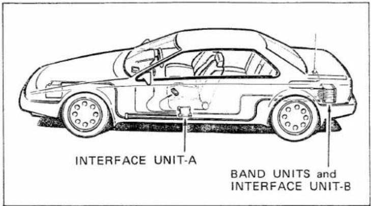
We recommend installing the IC-900A/E SUPER MULTI-BANDER SYSTEM in the following places:
INTERFACE UNIT-A:
Under or to the side of the driver's seat.
INTERFACE UNIT-B:
In the trunk near the antenna.
Each BAND UNIT:
Mount on INTERFACE UNIT-B.
natural_image
Interior view of a car showing dashboard, steering wheel, and rearview seat (no text or symbols)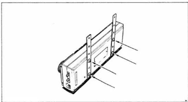
natural_image
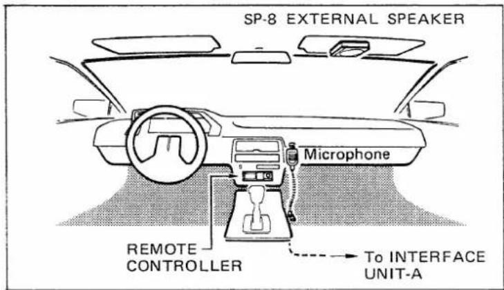
Technical line drawing of a mechanical component with mounting brackets and fasteners (no text or symbols)Select locations for the REMOTE CONTROLLER, the microphone, and speaker that do not interfere with the driver in any way.
To protect the mic connector cable from damage, the mic connector MUST be attached to the microphone connector support.
The REMOTE CONTROLLER may be placed on your vehicle dashboard or in another convenient place using either the supplied double-sided tape or the remote controller support brackets.
CAUTION:
AVOID mounting the REMOTE CONTROLLER in hot or cold places such as in front of the car heater or air conditioner, or in direct sunlight.
Attach the remote controller support brackets to the REMOTE CONTROLLER using the 4 supplied screws.
The optional MB-21 MOUNTING BRACKET is available for easy mounting.
4-2 UNIT CONNECTIONS
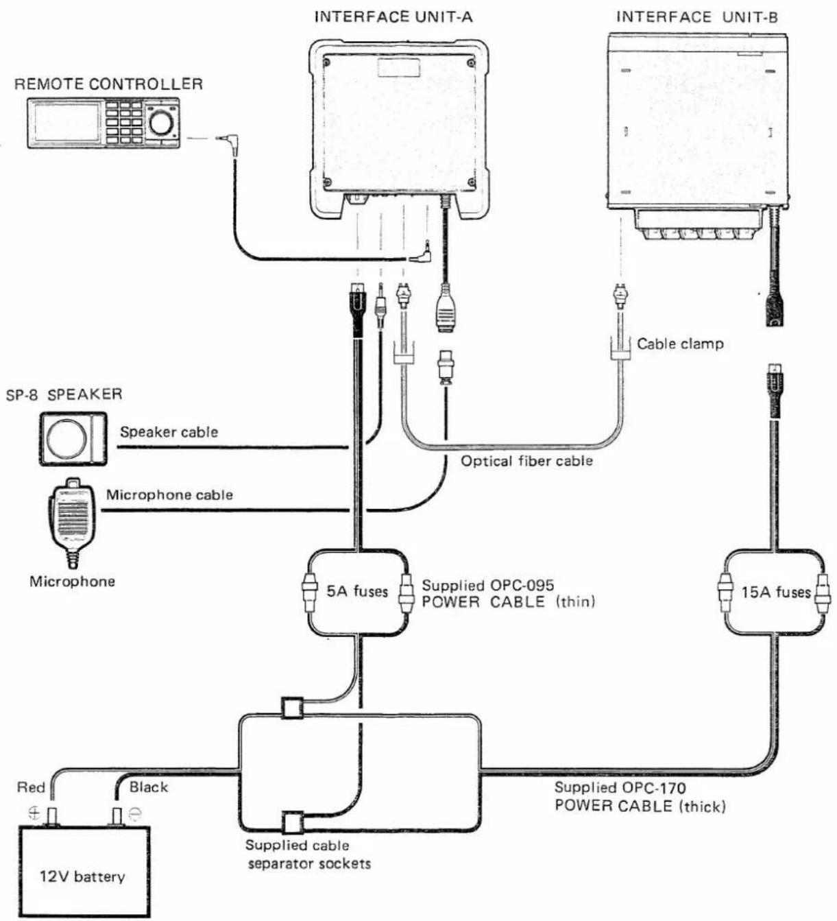
NOTE: Before installing the IC-900A/E MULTI-BANDER SYSTEM in your vehicle, we recommend that you preconnect each of the units in a separate place such as a desk or table to ensure correct connections.
To ensure stable operation we recommend purchasing the optional CF-11 COOLING FAN and connecting it to INTERFACE UNIT-B before installing the unit in the vehicle trunk.
The details of unit connections are described on the next pages.
flowchart
graph TD
    A["REMOTE CONTROLLER"] --> B["5A fuses"]
    C["SP-8 SPEAKER"] --> D["Speaker cable"]
    E["Microphone"] --> F["Microphone cable"]
    G["12V battery"] --> H["Red"]
    G --> I["Black"]
    J["INTVERAGE UNIT-A"] --> K["Cable clamp"]
    L["INTVERAGE UNIT-B"] --> M["Cable clamp"]
    K --> N["Optical fiber cable"]
    M --> O["15A fuses"]
    P["Supplied OPC-095 POWER CABLE (thin)"] --> Q["5A fuses"]
    R["Supplied OPC-170 POWER CABLE (thick)"] --> S["15A fuses"]
    T["Supplied cable separator sockets"] --> U["5A fuses"]
    V["Red"] --> W["12V battery"]
(1) POWER SOURCE CONNECTION
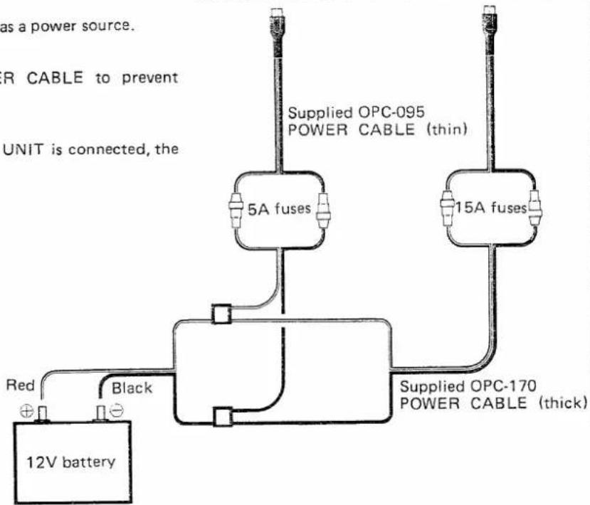
Use the supplied cable for direct connection to a 12V battery.
The red cable is POSITIVE and the black cable is NEGATIVE. DO NOT make incorrect connections.
CAUTION: Insulate the power cables by taping them if they pass through places where electrical shorts could occur.
- DO NOT connect the cable directly to a 24V battery.
- DO NOT use a cigarette lighter socket as a power source.
- We recommend the OPC-184 POWER CABLE to prevent voltage drops.
- When the UX-29H (45W type) BAND UNIT is connected, the OPC-184 should be used.
To INTERFACE UNIT-A To INTERFACE UNIT-B
flowchart
graph TD
    A["12V battery"] -->|Red| B["5A fuses"]
    A -->|Black| C["15A fuses"]
    B --> D["Supplied OPC-095 POWER CABLE (thin)"]
    C --> E["Supplied OPC-170 POWER CABLE (thick)"]
    style A fill:#f9f,stroke:#333
    style B fill:#ccf,stroke:#333
    style C fill:#cfc,stroke:#333
    style D fill:#fcc,stroke:#333
    style E fill:#fcc,stroke:#333
●Cable separator socket crimping
Power cables can be easily separated using the supplied cable separator socket. Observe the diagrams below and crimp the and sides of the cable.
NOTE: The optional OPC-184 POWER CABLE cannot use the separator socket.
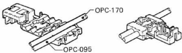
-
Set the cable in the socket groove without removing the vinyl jacket.
-
Close the socket top cover by shutting it over the cable.
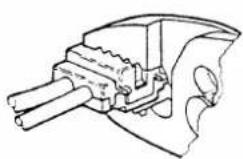
- Snap the socket top cover shut.
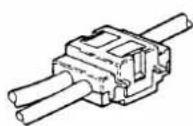
- The connection is complete.
(2) INTERFACE UNIT-A INSTALLATION
- Connections
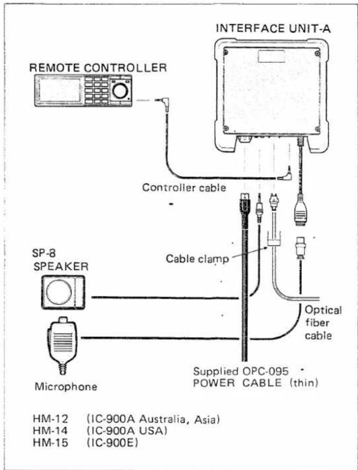
Connect the supplied OPC-095 POWER CABLE (thin) to the cable separator socket or battery directly.
To prevent accidental removal of the optical fiber cable the connector clamp MUST be used.
When one speaker is used, it should be connected to the [SPJ-1] JACK. If the speaker is connected to the [SPJ-2] JACK only the SUB BAND audio is emitted.
When two speakers are used, 2-band audio is separated.
- Installation
Install INTERFACE UNIT-A in a location near the driver's seat using the above accessories.
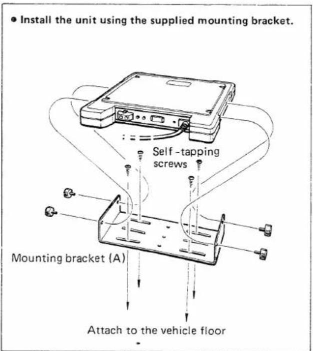
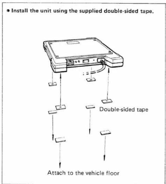
(3) INTERFACE UNIT-B INSTALLATION
- Connections
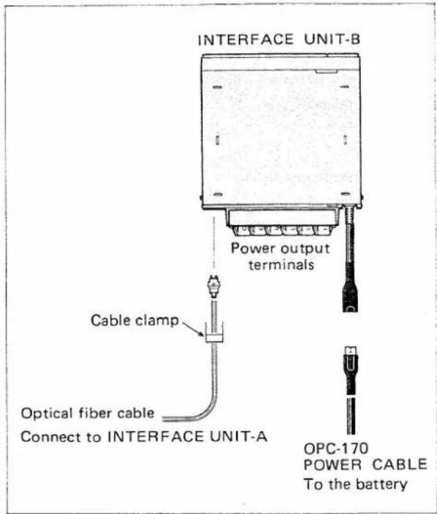
- Installation
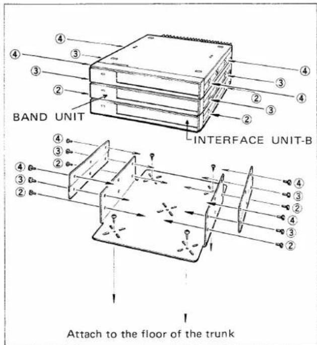
NOTE:
Install an optional CF-11 COOLING FAN on the rear panel of INTERFACE UNIT-B to obtain steady transceiver output power. The CF-11 will provide adequate ventilation in the vehicle trunk during the hot summer months or during transmissions of long duration.
Connect the supplied OPC-170 POWER CABLE (thick) to the battery directly.
INTERFACE UNIT-B has 6 power output connectors, so up to 6 BAND UNITS can be connected.
NOTE:
To prevent accidental removal of the optical fiber cable the connector clamp MUST be used.
We recommend installing INTERFACE UNIT-B in your vehicle's trunk.
1) Mount the bracket to the floor of the trunk using the supplied self-tapping screws. The supplied double-sided tape may also be used to mount the bracket.
2) After installing the bracket, screw INTERFACE UNIT-B to the bracket using the lower side holes.
3) Attach a BAND UNIT on INTERFACE UNIT-B and screw down the mounting bracket of the BAND UNIT.
4) Attach another BAND UNIT onto the previously attached BAND UNIT and screw down the mounting bracket.
5) To protect the BAND UNIT from dust, cover the rectangular holes on the top BAND UNIT with the supplied rubber bushings (S).
(4) INTERFACE UNIT-B AND BAND UNIT
●Front panel connection
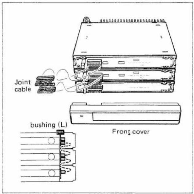
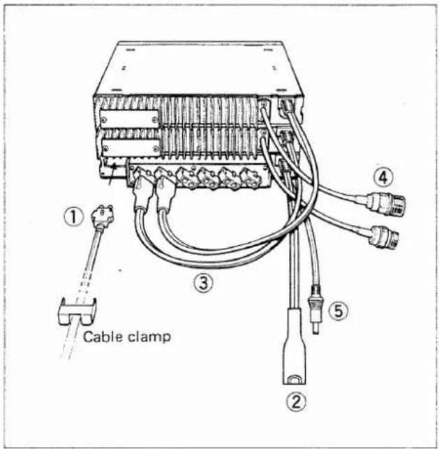
●Rear panel connection
1) Pull the front cover forward and remove it.
2) Plug in the joint cable as shown in the diagram.
Connect the joint cable between the INTERFACE UNIT-B connector and the lower side connector of the BAND UNIT. The upper side connector is used for the next BAND UNIT connection.
3) Cover the top hole on the front cover with a rubber bushing (L) to protect the unit from dust.
① OPTICAL FIBER CONNECTOR
Connect the optical cable to the rear panel of INTERFACE UNIT-B. DO NOT forget to use the cable clamp.
② POWER CABLE INPUT CONNECTOR
Connect the OPC-170 POWER CABLE (thick) to this connector.
③ BAND UNIT POWER CABLE
Connect to the power output terminal on INTERFACE UNIT-B.
④ ANTENNA CONNECTOR
Connect a 50Ω antenna here. Refer to p.12 for connector installation.
⑤ DC POWER OUTPUT FOR COOLING FAN
Connect an optional CF-11 COOLING FAN here for steady output power.
CAUTION:
DO NOT connect equipment other than BAND UNITS to the power output terminals. Other equipment may cause damage to the IC-900A/E.
(5) OPTICAL FIBER CABLE
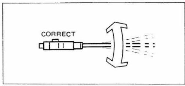
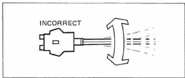
A new, reliable, bi-directional optical fiber cable is used to connect INTERFACE UNIT-A with INTERFACE UNIT-B. Observe the cautions below when connecting the optical fiber cable.
CAUTIONS:
- DO NOT bend the optical fiber cable to a radius of less than 25mm.
- DO NOT cut the optical fiber cable.
- DO NOT bend the optical fiber cable in a left or right angle as shown in the figure.
- Use the supplied connector clamp to secure the optical fiber cable connection.
4 - 3 OTHERS
Transceiver performance largely depends on the quality of the antenna used. Select a high-quality antenna and use it as recommended by the manufacturer.
(1) ANTENNA LOCATION
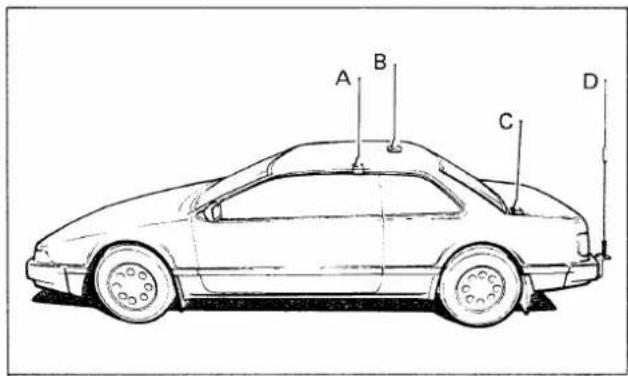
(2) DUPLEXER
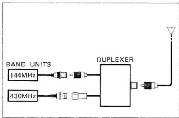
flowchart
graph LR
    A["BAND UNITS"] --> B["144MHz"]
    C["430MHz"] --> D["430MHz"]
    B --> E["DUPLEXER"]
    D --> E
    E --> F["Antenna"]
    F --> G["Antenna"]
A: Gutter-mount antenna
- Most popular mounting location.
B: Roof-mount antenna
- Best location for a good radiation pattern.
- Drill a hole in the roof, or use a magnetic antenna base.
C: Trunk-mount antenna
D: Bumper-mount antenna
- Best location for a longer antenna.
When using a dual-band antenna (i.e., 144MHz/430MHz or 430MHz/1200MHz), the duplexer must be used.
(3) COAXIAL CABLE
When using a coaxial cable the UHF band signal strength is diminished, so be sure to use a 50Ω coaxial cable that is as short and thick as possible.
(4) CONNECTOR INSTALLATION
- PL-259 connector installation
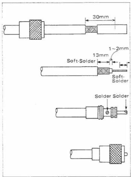
1) Slide the coupling ring over the coaxial cable.
2) Strip the cable as shown in the figure, then tin approx. 13mm (1/2") of the shield conductor. Remove the outer plastic casing and strip the center conductor insulation as shown in the figure. Tin the center conductor. Soft-solder the shield conductor and center conductor.
3) Slide the connector body onto the cable and solder.
4) Screw the coupling ring onto the connector body.
● TYPE-N connector installation
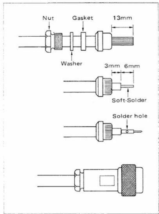
1) Slide the nut, washer, and rubber gasket over the coaxial cable.
2) Strip the cable as shown in the figure, then tin approx. 13mm (1/2") of the shield conductor and fold the braid back over the clamp. The clamp end should be flush with the end of the braid ends.
Cut and remove 6mm (1/4") of the shield conductor and the center conductor insulation.
3) Soft-solder the center conductor. Install a center conductor pin and solder it.
4) Carefully slide the plug body into place aligning the center conductor pin on the cable with the hold in the insulator inside the plug body.
Complete the assembly by screwing the nut into the plug body.
(5) MICROPHONE
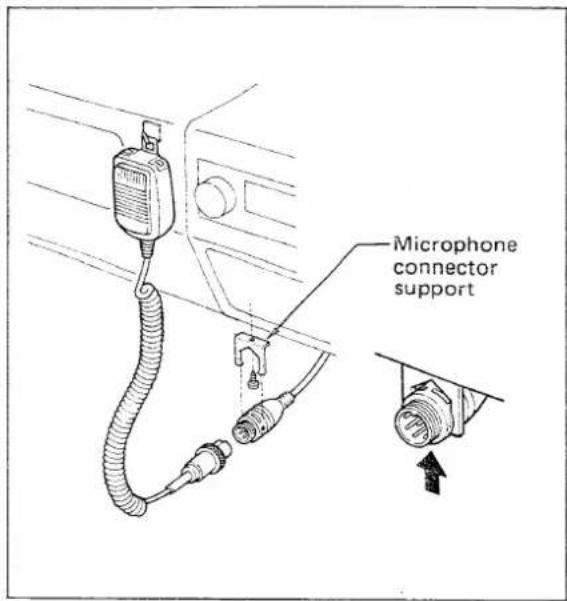
Connect the microphone to the INTERFACE UNIT-A mic connector cable.
The mic connector MUST be attached to the microphone connector support to protect the mic connector from damage.
DO NOT allow the mic connector to be grounded to any metal parts of the vehicle or RF feedback could occur.
Outside view
(INTERFACE UNIT-A side)
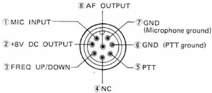
The following options are easy to use and install, and will increase your enjoyment of radio communications.
(6) OPTIONS
SP-10 EXTERNAL SPEAKER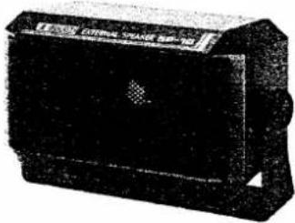 | SP-8 EXTERNAL SPEAKER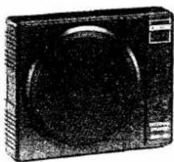 |
MB-21 REMOTE CONTROLLER BRACKET | CF-11 COOLING FAN KIT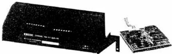 |
IC-PS30 AC POWER SUPPLY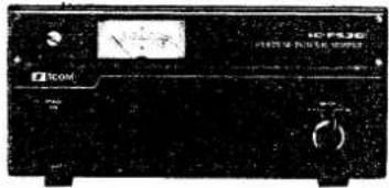 | HS-15 HS-15SBFLEXIBLE MOBILE SWITCH BOXMICROPHONE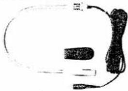 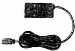 |
5. PRE-OPERATION
CONFIRMATION OF INSTALLATION
After making connections, re-check the following points:
- Make sure INTERFACE UNIT-A and INTERFACE UNIT-B are connected with a cable from the battery or power source.
- Make sure the connection of INTERFACE UNIT-A to INTERFACE UNIT-B is completely secure.
- Make sure the BAND UNITS are mounted and fixed securely to INTERFACE UNIT-B.
- Make sure every BAND UNIT is securely connected.
- Make sure the cable clamp is used to hold the optical fiber cable in place.
- Make sure the radius of the optical fiber cable bend is greater than 25mm.
POWER ON
After confirming the above, push the [POWER] SWITCH on the REMOTE CONTROLLER to turn power ON.
- When the correct connection is made
1) More than two BANDUNITS are connected.
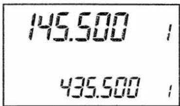
2) One BAND UNIT is connected.
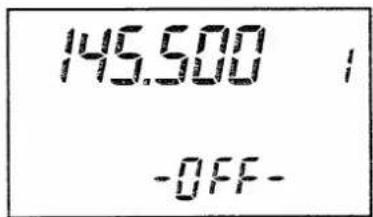
When more than two BAND UNITS are connected, the FUNCTION DISPLAY lights up as shown above. Check the connections again.
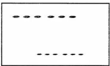
- When the wrong connection is made
natural_image
Simple diagram with a row of black dots and a horizontal line, no text or symbols present.When the FUNCTION DISPLAY lights up as shown at left, check the connection again and refer to SECTION 4 - 2 UNIT CONNECTIONS.
6. BASIC OPERATIONS
This section explains basic operation in receiving and transmitting. Additional operations are described in SECTION 8 FUNCTION OPERATIONS.
6 - 1 RECEIVING
Two separate audio bands can be displayed and emitted from the speaker at the same time. Simultaneous 2-band watching is therefore possible.
NOTE: 2-band audio can be separated when two external speakers are used.
1) Push [POWER] SWITCH.
2) Select required band.
3) Push [SQL-▼] SWITCH.
4) Push [VOL-▲] or [VOL-▼] SWITCH.
5) Push [SQL-▲] SWITCH.
6) Push [SUB] SWITCH.
1) Push the [POWER] SWITCH to turn power ON.
- The [POWER] SWITCH alternately turns power ON and OFF.
2) When more than 3 BAND UNITS are connected and the required band is not indicated on the FUNCTION DISPLAY, the required band can be selected as follows:
- Push and hold the [SET] SWITCH and then rotate the TUNING CONTROL.
3) Push the (SQL-▼] SWITCH until the green [MAIN T/R] IN-DICATOR lights up to open the squelch function.
- When the [SQL-▼] SWITCH is held down, the S/RF INDICATOR lights up and indicates the squelch level.
4) Push the [VOL-▲] or [VOL-▼] SWITCH to adjust the transceiver to a suitable audio level.
- When the [VOL-A] or [VOL-V] SWITCH is held down, the S/RF INDICATOR lights up and indicates the volume level.
5) Push the [SQL-▲] SWITCH until the noise is quieted.
- The squelch circuit mutes all noise from the speaker when no signal is received. This is useful while waiting for another station to call.
6) Push the [SUB] SWITCH to control the SUB BAND. Follow steps 1) \~ 3) above to adjust the volume and squelch levels.
- "SUB" appears on the FUNCTION DISPLAY.
- If no switch is pushed, after 30 seconds the IC-900A/E automatically returns to the MAIN BAND.
7) Push [SUB] SWITCH again.
8) Select MAIN BAND frequency.
9) Select SUB BAND frequency.
10) Mute SUB BAND.
●RIT/VXO Operation

in 1200MHz BAND
7) Push the [SUB] SWITCH again to return to the MAIN BAND.
- “SUB” disappears from the FUNCTION DISPLAY.
- To change between the MAIN and SUB BANDS push the [M/S] SWITCH alternately. Refer to p. 17 for details.
8) Rotate the TUNING CONTROL to select the required frequency on the MAIN BAND.
- For quick tuning, the [MHz] or [TS] SWITCHES are helpful. Refer to p. 31 for details.
9) Push the [SUB] SWITCH and then rotate the TUNING CONTROL to select a frequency on the SUB BAND.
The [MHz] or [TS] SWITCHES can be used also on the SUB BAND.
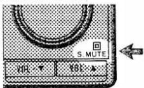
10) To mute audio on the SUB BAND, push the [S-MUTE] SWITCH IN.
When the UX-129 1200MHz BAND UNIT is connected, the RIT or VXO function can be used for fine tuning.
RIT : Receive frequencies can be changed within a range of ±7kHz. VXO : Both receive and transmit frequencies can be changed within a range of ±7kHz.
The RIT and VXO functions and TUNING STEP (B) function are programmed in SET MODE. Refer to p. 31 for RIT or VXO function programming information.
1) Push the [TS] SWITCH to turn the RIT or VXO function ON.
- “RIT” or “VXO” appears on the FUNCTION DISPLAY.
2) Rotate the TUNING CONTROL to adjust the frequency.
- The displayed frequency does not change even when the TUNING CONTROL is rotated.
3) Push the [TS] SWITCH again to cancel the RIT or VXO function.
6 - 2 TRANSMITTING
It is possible to transmit only in the MAIN BAND.
NOTE: Even when in the SUB BAND ("SUB" lights up) a signal is transmitted on the MAIN BAND frequency.
1) Select MAIN BAND.
M/S
1) If the transceiver is set in the SUB BAND, push the [SUB] SWITCH to call the MAIN BAND, and select the required band using the [M/S] SWITCH.
![MAIN BAND (transmitting possible) Push [M/S] SWITCH 435.500 9 SUB BAND (receiving only)](/content/2026/05/777918/images/5c91746eaeb3ef12394b1c16083e291a159f3dec4adc8bf798d743951ed200f4.jpg)
2) Select output power.
HI/LO
3) Push [PTT] SWITCH.
2) Push the [HI/LO] SWITCH to alternately select HIGH and LOW output power.
3) Push the [PTT] SWITCH on the microphone to begin transmitting.
- The red [MAIN T/R] INDICATOR lights up and the "S/RF" INDICATOR shows the relative output power.
4) Speak into microphone.
4) Speak into the microphone using your normal voice level.
- Do not hold the microphone too closely to your mouth or speak too loudly. This may distort the signal.
5) Release [PTT] SWITCH.
5) Release the [PTT] SWITCH on the microphone to return to receiving.
NOTE: The SUB BAND can receive a signal even when you are transmitting in the MAIN BAND. However, there may be some interference depending on the transmit and receive frequencies.
● Repeater operation
1) Select Duplex mode.

2) Push [TONE] SWITCH.

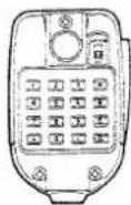
3) Transmit DTMF signals. (USA version)
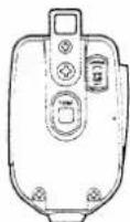
4) Transmit a 1750Hz tone. (Europe version)
5) Check transmit frequency.

To access a repeater the transceiver must be in Duplex mode. Some repeaters require a tone to open the circuit.
1) Push the [DUP] SWITCH one time for -Duplex or two times for +Duplex mode and one additional time to return to Simplex mode. Offset frequency programming is described on p. 31.
- Either of the following indicators appear on the FUNCTION DISPLAY.
“-DUP”:The transmit frequency is lower than the receive frequency. “DUP”:The transmit frequency is higher than the receive frequency.
- “TONE” appears if a subaudible tone is programmed. Refer to p. 32 for programming a subaudible tone frequency.
2) Push the [TONE] SWITCH to alternately turn a subaudible tone ON and OFF.
3) If it is necessary to transmit DTMF signals to access a repeater, push and hold the [PTT] SWITCH and then push the required number keys on the keyboard of the HM-14 DTMF MICROPHONE.
4) If it is necessary to transmit a 1750Hz tone for access to a repeater, push and hold the [TONE] SWITCH on the rear of the HM-15 MICROPHONE for approx. 1 \~ 3 seconds.
5) Push the [CHECK] SWITCH to monitor the transmit frequency (repeater input frequency) when in Duplex mode.
- This allows checking of the signal strength of your contacted station directly without going through a repeater.
If the signal strength is enough for receiving both stations, you should move to a simplex frequency.
7. CONTROL FUNCTIONS
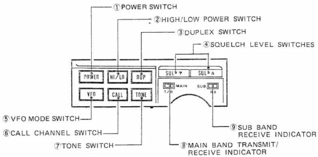
7-1 REMOTE CONTROLLER
| 1 POWER SWITCH [POWER] | This switch turns the REMOTE CONTROLLER, INTERFACE UNIT-A, INTERFACE UNIT-B and each selected BAND UNIT ON and OFF. |
| 2 HIGH/LOW POWER SWITCH [HI/LO] | This switch selects transmitter HIGH and LOW output power alternately. Output power is described on p. 2. |
| 3 DUPLEX SWITCH [DUP] | This switch repeatedly selects the -Duplex, +Duplex and Simplex modes. |
| 4 SQUELCH LEVEL SWITCHES [SQL-Δ] [SQL-7] | These switches increase or decrease the squelch threshold level. |
| 5 VFO MODE SWITCH [VFO] | This switch selects VFO mode. |
| 6 CALL CHANNEL SWITCH [CALL] | This switch alternately calls and cancels the CALL CHANNEL. Refer to p. 28 for CALL CHANNEL programming information. |
| 7 TONE SWITCH [TONE] | This switch turns the subaudible, tone encoder alternately ON and OFF. The subaudible tone can be programmed in SET MODE. Refer to p. 32 for subaudible tone frequency programming information. |
| 8 MAIN BAND TRANSMIT/ RECEIVE INDICATOR [MAIN T/R] | This indicator lights up in green while the MAIN BAND squelch is open, and in red while the transceiver is transmitting. |
| 9 SUB BAND RECEIVE INDICATOR [SUB RX] | This indicator lights up in green while the SUB BAND squelch is open. |
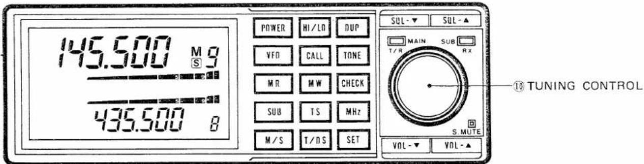
| 10 TUNING CONTROL | This control selects the operating frequency in VFO mode and memory channel in MEMORY mode. |
| This control also selects some parameters while the transceiver is in SET MODE. Refer to SECTION 9 for each setting. | |
| When the UX-129 1200MHz BAND UNIT is used, this control also selects the RIT/VXO frequency shift. | |
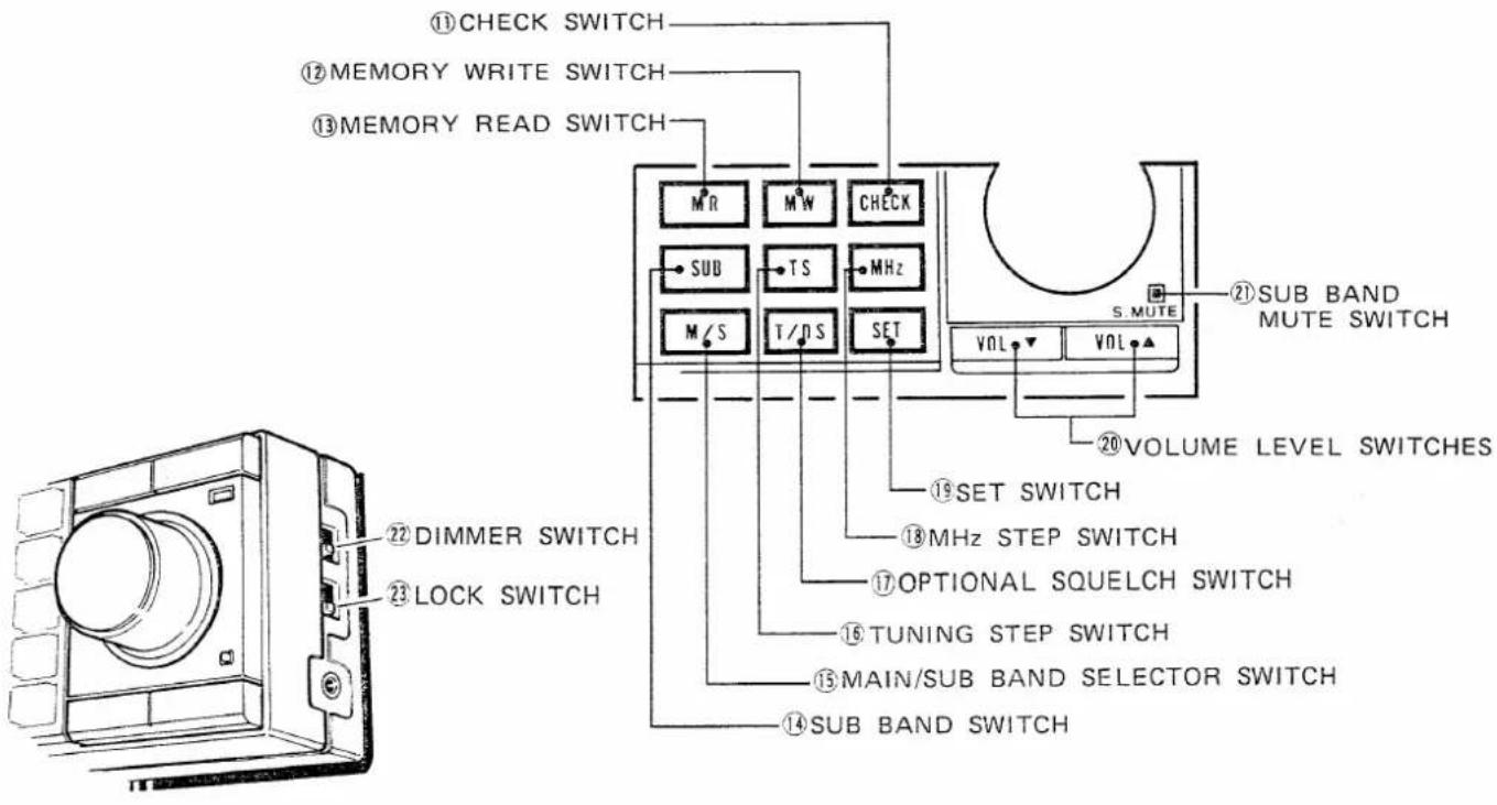
| 11 CHECK SWITCH [CHECK] | This switch monitors the transmit frequency (repeater input frequency) during Duplex operation. |
| NOTE: The check function operates on the MAIN BAND frequency even if the SUB BAND is selected. | |
| 12 MEMORY WRITE SWITCH [MW] | This switch stores displayed information from the VFO to memory channels or vice versa. Refer to p. 26 for details. |
| This switch is also used for CALL CHANNEL programming. Refer to p. 28 for details. |
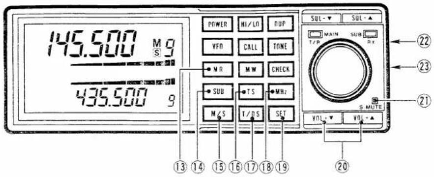
| 13 MEMORY READ SWITCH [MR] | In VFO mode, this switch selects MEMORY mode. Refer to p. 26 for details.In MEMORY mode, this switch alternately sets or cancels the memory skip channel. Refer to p. 28 for details. |
| 14 SUB BAND SWITCH [SUB] | This switch alternately calls and cancels the SUB. BAND used for operating controls. |
| 15 MAIN/SUB BAND SELECTOR SWITCH [M/S] | This switch alternately selects the SUB and MAIN BANDS for transmitting. |
| 16 TUNING STEP SWITCH [TS] | This switch selects the tuning step increment.The tuning step increment can be programmed in SET MODE.Refer to p. 31 for tuning step increment programming information.When the UX-129 1200MHz BAND UNIT is used, this switch also operates the RIT/VXO function. |
| 17 OPTIONAL SQUELCH SWITCH [T/DS] | This switch turns ON and OFF the optional squelch system. |
| 18 MHz STEP SWITCH [MHz] | This switch sets the tuning step rate for 1MHz steps in any band. |
| 19 SET SWITCH [SET] | This switch selects SET MODE to program each parameter. Refer to SECTION 9 SET MODE for details. |
| 20 VOLUME LEVEL SWITCHES [VOL-▼] [VOL-▲] | These switches increase or decrease the audio level.• [VOL-▲] : increase[VOL-▼] : decrease |
| 21 SUB BAND MUTE SWITCH | This switch mutes the SUB BAND audio. The displayed MHz frequency of the SUB BAND flashes when being muted. |
| 22 DIMMER SWITCH [DIM] | This switch dims the intensity of the FUNCTION DISPLAY. |
| 23 LOCK SWITCH [LOCK] | This switch inhibits every switch function except the following:[SQL-▲], [SQL-▼], [VOL-▲], [VOL-▼], [CHECK], [S.MUTE], [DIM], [PWR] |
7 - 2 FUNCTION DISPLAY
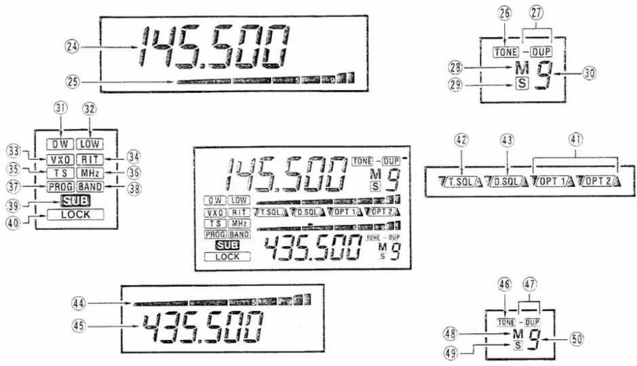
②4 MAIN BAND FREQUENCY READOUT
This readout shows the operating frequency in OPERATING MODE and each programmable parameter in SET MODE of the MAIN BAND.
⑲ MAIN BAND S/RF INDICATOR
This indicator shows signal strength in receive mode and RF output power in transmit mode on the MAIN BAND.
This indicator also shows the audio level or squelch threshold level when the [VOL-▼], [VOL-▲], [SQL-▼] or [SQL-▲] SWITCH is held down.
⑳ MAIN BAND TONE INDICATOR
This indicator appears when the MAIN BAND subaudible tone is turned ON.
When this indicator flashes in SET MODE the subaudible tone can be programmed.
⑳ MAIN BAND DUPLEX INDICATOR
Either “-DUP” or “DUP” appears when the MAIN BAND is in Duplex mode.
⑳ MAIN BAND MEMORY MODE INDICATOR
This indicator appears when the MAIN BAND is in MEMORY mode.
⑲ MAIN BAND SKIP CHANNEL INDICATOR
This indicator appears when the displayed memory channel is programmed for skip scan in MEMORY mode.
③0 MAIN BAND MEMORY CHANNEL READOUT
This readout shows the selected memory channel of the MAIN BAND.
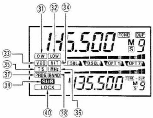
| 31 OFFSET WRITE INDICATOR | When this indicator flashes in SET MODE the offset frequency can be programmed. |
| 32 LOW POWER INDICATOR | This indicator appears when LOW output power is selected. |
| 33 VXO INDICATOR | This indicator appears when the VXO function is selected with the UX-129 1200MHz BAND UNIT.This indicator does not appear while another BAND UNIT is operating. |
| 34 RIT INDICATOR | This indicator appears when the RIT function is selected with the UX-129 1200MHz BAND UNIT.This indicator does not appear while another BAND UNIT is operating. |
| 35 TUNING STEP INDICATOR | This indicator appears when the secondary tuning step is selected.When this indicator flashes in SET MODE the tuning step increment can be programmed. |
| 36 MHz STEP INDICATOR | This indicator appears when the MHz step is selected. |
| 37 PROGRAMMED SCAN BANDEGE INDICATOR | When this indicator flashes in SET MODE the band edges for the PROGRAMMED SCAN can be programmed. |
| 38 BAND UNIT SELECTING INDICATOR | When this indicator flashes in SET MODE the operating BAND UNITS can be selected.When only one or two BAND UNITS are connected this indicator does not flash. |
| 39 SUB BAND INDICATOR | This indicator appears when the SUB BAND is selected. |
| 40 LOCK INDICATOR | This indicator appears when the [LOCK] SWITCH is ON. |
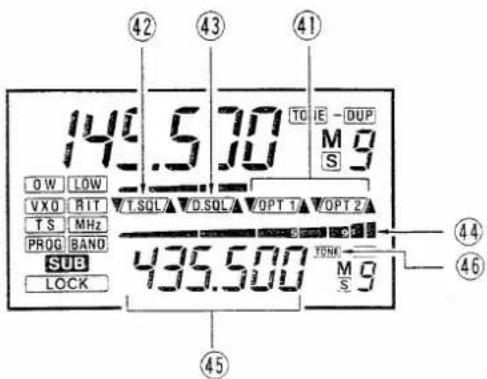
④1 OPTIONAL UNIT SELECTING INDICATORS
. These indicators appear when the optional units are installed.
“▲” or “▼” indicates that either the MAIN or SUB BAND is connecting the optional unit.
④2 OPTIONAL TONE SQUELCH INDICATOR
This indicator appears when the optional UT-29 TONE SQUELCH UNIT is turned ON.
“▲” or “▼” indicates that either the MAIN or SUB BAND is operating the TONE SQUELCH UNIT.
This indicator does not appear when the TONE SQUELCH UNIT is not installed.
④3 OPTIONAL DIGITAL CODE SQUELCH INDICATOR
This indicator appears when the optional UT-28 DIGITAL CODE SQUELCH UNIT is turned ON.
“▲” or “▼” indicates that either the MAIN or SUB BAND is operating the DIGITAL CODE SQUELCH UNIT.
This indicator does not appear when the DIGITAL CODE SQUELCH UNIT is not installed.
④4 SUB BAND SIGNAL INDICATOR
This indicator shows the signal strength of the SUB BAND.
This indicator also shows the audio level or squelch threshold level when the [VOL-▼], [VOL-▲], [SQL-▼] or [SQL-▲] SWITCH is held down.
④5 SUB BAND FREQUENCY READOUT
This readout shows the operating frequency in OPERATING MODE and each programmable parameter in SET MODE of the SUB BAND.
④6 SUB BAND TONE INDICATOR
This indicator appears when the SUB BAND subaudible tone is programmed.
When this indicator flashes in SET MODE the subaudible tone can be programmed. However, this program can be used for transmitting only after changing from the SUB BAND to the MAIN BAND.
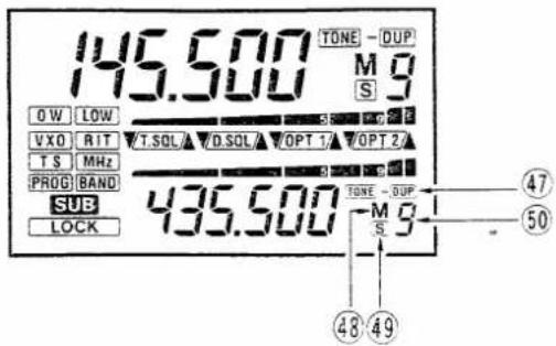
④7 SUB BAND DUPLEX INDICATOR
Either “-DUP” or “DUP” appears when the SUB BAND is in Duplex mode. However, this mode can be used for transmitting only after changing from the SUB BAND to the MAIN BAND.
④8 SUB BAND MEMORY INDICATOR
This indicator appears when the SUB BAND is in MEMORY mode.
④9 SUB BAND SKIP CHANNEL INDICATOR
This indicator appears when the displayed memory channel is programmed for skip scan and in MEMORY mode.
⑤0SUB BAND MEMORY CHANNEL READOUT
This readout shows the selected memory channel of the SUB BAND.
7 - 3 MICROPHONE
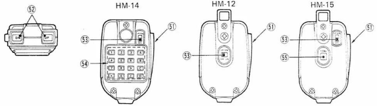
⑤1 PTT SWITCH
Push this switch to begin transmitting.
⑤2 UP/DOWN SWITCH
Push either of these switches to increase or decrease frequencies or memory channel numbers depending on the mode.
Push and hold either of these switches to start the scan function. Refer to SECTION 8 - 2 SCAN OPERATIONS.
⑤3 UP/DOWN ON-OFF SWITCH
When this switch is OFF, the [UP]/[DN] SWITCHES do not operate. This feature eliminates accidental or unwanted scanning.
⑤4 DTMF KEYPAD (HM-14 Only)
While pushing the [PTT] SWITCH, push the DTMF KEYPAD to transmit DTMF signals.
⑤5 TONE CALL SWITCH (HM-15 Only)
Push this switch to transmit a 1750Hz tone.
8. FUNCTION OPERATIONS
8-1 MEMORY OPERATIONS
The IC-900A/E has ten memory channels on each band. The operating frequency, Duplex condition, subaudible tone frequency and channel skip function may be assigned to each memory channel whether the transceiver is in VFO mode or MEMORY mode.
(1) MEMORY READING

in VFO mode
1) Select the required band (MAIN or SUB BAND) with the [SUB] SWITCH.
2) Push the [MR] SWITCH to call MEMORY mode.
- "M" appears on the MAIN BAND or SUB BAND side depending on whether "SUB" appears or not.
- If the [MR] SWITCH is pushed two times, the memory skip function is programmed on the memory channel. Refer to p. 28 for details.
3) Select a desired memory channel by rotating the TUNING CONTROL or pushing the [DN]/[UP] SWITCH on the microphone.
- If the [DN]/[UP] SWITCH is held for more than 0.5 seconds, the scan function starts. Refer to p. 27 for details.
(2) MEMORY WRITING

in VFO mode
1) Select the required band (MAIN or SUB BAND) with the [SUB] SWITCH.
2) Select a desired memory channel to be programmed on MEMORY mode.
3) Push the [VFO] SWITCH to select VFO mode.
4) Select the information you wish to write into a memory channel.
5) Push and hold the [MW] SWITCH until three beep tones are emitted to store information in the memory channel.
(3) MEMORY TRANSFERS

in MEMORY mode
The memorized information can be transferred to VFO mode.
1) Select the required band (MAIN or SUB BAND) with the [SUB] SWITCH.
2) Select a memory channel containing the information to be transferred.
3) Push and hold the [MW] SWITCH until three beep tones are emitted.
- The transceiver returns to VFO mode automatically.
8-2 SCAN OPERATIONS
(1) PROGRAMMED SCAN
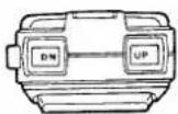
in VFO mode
The IC-900A/E comes equipped with two scan systems; programmed scan and memory scan.
Programmed scan searches between the programmed scan edges. Refer to p. 32 for programming the scan edges.
1) Select the required band (MEMORY or SUB BAND) with the [SUB] SWITCH.
2) Push the [SQL-▲] SWITCH until the receive noise is quieted.
3) Select VFO mode by pushing the [VFO] SWITCH if MEMORY mode or a CALL CHANNEL is selected.
4) Push and hold the [DN] or [UP] SWITCH on the microphone to start the scan function.
• The decimal point blinks.
- [DN] : Scan starts and moves downward. [UP] : Scan starts and moves upward.
- When a signal is received the scan stops for approx. 10 seconds.
5) To stop the scan function push the [DN] or [UP] SWITCH on the microphone.
- Rotating the TUNING CONTROL or pushing another switch can also stop the scan function.
(2) MEMORY SCAN
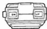
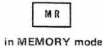
in MEMORY mode
The memory scan searches all 10 memory channels except the skip channels.
1) Select the required band (MAIN or SUB BAND) with the [SUB] SWITCH.
2) Push the [SQL-▲] SWITCH until the receive noise is quieted.
3) Select MEMORY mode if the transceiver is in VFO mode via the [MR] SWITCH.
- If the [MR] SWITCH is pushed in MEMORY mode the displayed memory channel is programmed as a skip channel.
4) Push the [DN] or [UP] SWITCH on the microphone to start the scan function.
• The decimal point blinks.
• [DN] : Scan starts and moves downward. [UP] : Scan starts and moves upward.
- When a signal is received the scan stops for approx. 10 seconds.
(3) SKIP CHANNEL
5) To stop the scan function push the [DN] or [UP] SWITCH on the microphone.
- Rotating the TUNING CONTROL or pushing another switch can also stop the scan function.
An unrequired memory channel can be skipped during MEMORY SCAN.
1) Select MEMORY mode and then rotate the TUNING CONTROL to select a required memory channel to skip.
2) Push the [MR] SWITCH to program the skip channel.
- "S" appears.
- This channel will be skipped during MEMORY SCAN operation.
3) To clear the skip channel, push the [MR] SWITCH again.
8-3 CALL CHANNEL OPERATIONS
(1) CALL CHANNEL READ
Your highest priority channel can be easily called from a programmed CALL CHANNEL.
1) Select the required band (MAIN or SUB BAND) with the [SUB] SWITCH.
2) Push the [CALL] SWITCH.
- "C" appears instead of a memory channel number.
- The TUNING CONTROL does not operate during CALL CHANNEL operations.
3) To cancel the CALL CHANNEL, push the [CALL] SWITCH again or push the [VFO] or [MR] SWITCH.
(2) PROGRAMMING
1) Select the required band (MAIN or SUB BAND) with the [SUB] SWITCH.
2) If MEMORY mode or the CALL CHANEL is selected, push the [VFO] SWITCH.
3) Select the information you wish to write into the CALL CHANNEL.
4) Push the [CALL] SWITCH to read the CALL CHANNEL.
5) Push and hold the [MW] SWITCH until three beep tones are emitted.
- Your required information is now stored.
8 - 4 BEEP TONE ON AND OFF
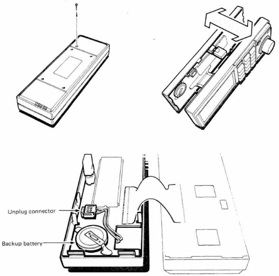
A beep tone is emitted each time a switch is pushed on the REMOTE CONTROLLER. If you do not require beep tones, they can be eliminated by unplugging a connector inside the REMOTE CONTROLLER. Follow the directions below.
1) Turn power to the REMOTE CONTROLLER OFF and remove the controller cable.
2) Remove the screw from the rear panels of the REMOTE CONTROLLER.
3) Separate the front and rear panels as shown in the diagram.
4) Unplug the connector as shown in the diagram.
5) Re-attach the front and rear panels, and reinsert the screw removed in step 2) above.
9. SET MODE
The IC-900A/E has a convenient SET MODE for programming the tuning step, offset frequency, subaudible tone frequency, scan edges, band selection, etc.
When the [SET] SWITCH is pushed the IC-900A/E will move through the SET MODE cycle shown below. When returning to SET MODE from OPERATING MODE, the cycle will begin again at the place where it last stopped.
9-1 SET MODE CONSTRUCTION
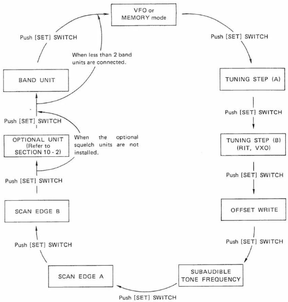
flowchart
graph TD
    A["VFO or MEMORY mode"] -->|Push["SET"] SWITCH| B["BAND UNIT"]
    A -->|Push["SET"] SWITCH| C["TUNING STEP (A)"]
    B -->|Push["SET"] SWITCH| D["OPTIONAL UNIT\n(Refer to SECTION 10 - 2)"]
    C -->|Push["SET"] SWITCH| E["TUNING STEP (B)\n(RIT, VXO)"]
    D -->|Push["SET"] SWITCH| F["SCAN EDGE B"]
    E -->|Push["SET"] SWITCH| G["OFFSET WRITE"]
    F -->|Push["SET"] SWITCH| H["SCAN EDGE A"]
    G -->|Push["SET"] SWITCH| H
    H -->|Push["SET"] SWITCH| I["SUBAUDIBLE TONE FREQUENCY"]
    I -->|Push["SET"] SWITCH| H
    style A fill:#f9f,stroke:#333
    style B fill:#ccf,stroke:#333
    style C fill:#cfc,stroke:#333
    style D fill:#fcc,stroke:#333
    style E fill:#cff,stroke:#333
    style F fill:#ffc,stroke:#333
    style G fill:#fcc,stroke:#333
    style H fill:#ffc,stroke:#333
    style I fill:#fcc,stroke:#333
9 - 2 TUNING STEP (A)
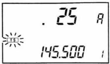
When "TS" does not appear on the FUNCTION DISPLAY the IC-900A/E changes in this tuning step while the TUNING CONTROL is rotated.
1) Push the [TS] SWITCH several times until "TS" flashes and "A" appears in place of the memory channel number.
2) Rotate the TUNING CONTROL to select the required tuning step increment.
3) Push the [SET] SWITCH to program the TUNING STEP (B) or push the [VFO] or [MR] SWITCH to return to OPERATING MODE.
9 - 3 TUNING STEP (B)
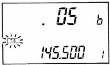
When "TS" appears on the FUNCTION DISPLAY the IC-900A/E changes the frequency in this tuning step while the TUNING CONTROL is rotated.
When using the 1200MHz band the RIT or VXO function can be selected using the TUNING STEP (B).
1) Push the [TS] SWITCH several times until "TS" flashes and "b" appears in place of the memory channel number.
2) Rotate the TUNING CONTROL to select the required tuning step increment.
- When the 1200MHz band is used "RIT", "VXO" and "TS" appear repeatedly.
3) Push the [SET] SWITCH to program the offset frequency or push the [VFO] or [MR] SWITCH to return to OPERATING MODE.
9 - 4 OFFSET WRITE
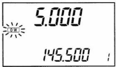
When Duplex mode is selected the transmitter frequency is lower or higher than the receiver frequency with this offset.
1) Push the [SET] SWITCH several times until "OW" flashes.
2) Rotate the TUNING CONTROL to select your required offset frequency.
- For quick selecting, the [MHz] or [TS] SWITCHES are helpful.
3) Push the [SET] SWITCH to program the subaudible tone frequency or push the [VFO] or [MR] SWITCH to return to OPERATING MODE.
9 - 5 SUBAUDIBLE TONE FREQUENCY
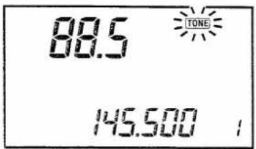
One of 38 different subaudible tone frequencies can be programmed to access a repeater.
1) Push the [SET] SWITCH several times until " TONE " flashes.
2) Rotate the TUNING CONTROL to select your required sub-audible tone frequency.
3) Push the [SET] SWITCH to program the scan edges or push the [VFO] or [MR] SWITCH to return to OPERATING MODE.
9-6 SCAN EDGES
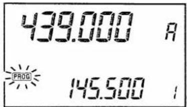
The purpose of PROGRAMMED SCAN is to monitor a particular section of the band. PROGRAMMED SCAN edges are programmed in the following way:
1) Push the [SET] SWITCH several times until "PROG" flashes and "A" appears in place of the memory channel number.
2) Rotate the TUNING CONTROL to select an upper or lower scan edge.
3) Push the [SET] SWITCH one time.
- "PROG" flashes and "b" appears in place of the memory channel number.
4) Rotate the TUNING CONTROL again to select the other side of the scan edges set in step 2).
5) Push the [SET] SWITCH to program the next parameter or push the [VFO] or [MR] SWITCH to return to OPERATING MODE.
9 - 7 BAND UNIT
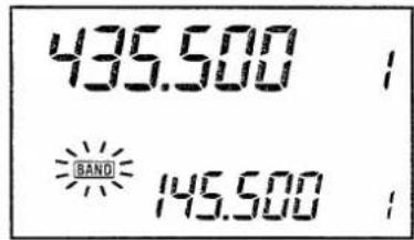
When less than two BAND UNITS are connected this section is skipped on the IC-900A/E.
When more than three BAND UNITS are connected the BAND UNITS are selected in the following way:
1) Push the [SET] SWITCH several times until "BAND" flashes.
2) Rotate the TUNING CONTROL to select the desired band.
3) Push the [SET] SWITCH repeatedly to program the next parameter or push the [VFO] or [MR] SWITCH to return to the OPERATING MODE.
10. OPTIONAL SQUELCH UNIT
The IC-900A/E can operate with interference-free communications using the UT-28 DIGITAL CODE SQUELCH UNIT or the UT-29 TONE SQUELCH UNIT.
10 - 1 UT-28 AND UT-29 INSTALLATION
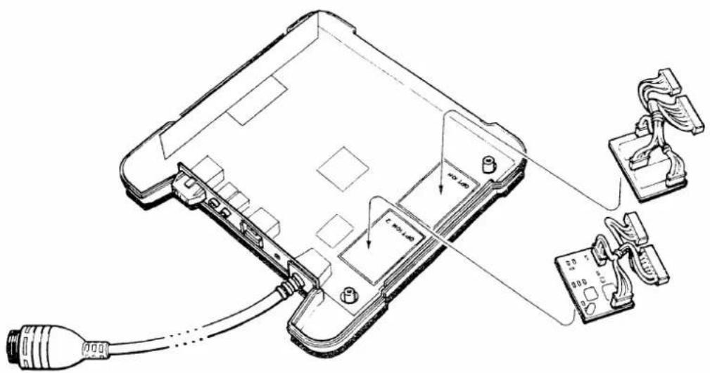
INTERFACE UNIT-A has installation positions where OPTION 1 and OPTION 2 are marked. The UT-28 and UT-29 can be installed in either of these positions.
CAUTION: Unplug the power cable before performing any work on the transceiver.
1) Unscrew the four screws on the INTERFACE UNIT-A top cover and remove the cover.
2) Install the unit either in the OPTION 1 or OPTION 2 position as shown in the diagram.
NOTE: If both the UT-28 and UT-29 are installed, make a note which unit is installed in which position.
3) Connect the 8-pin and 10-pin plugs from the units to connectors located nearby as shown in the diagram.
4) Remove adhesive tape and attach to each unit properly.
5) Re-attach the cover to INTERFACE UNIT-A.
10 - 2 UT-28 AND UT-29 SELECTION
Both the UT-28 and UT-29 can be used with the IC-900A/E. However, one band controls either the UT-28 or UT-29, so choose which unit to use on which band.
1) Push the [POWER] SWITCH to turn power ON.
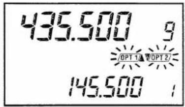
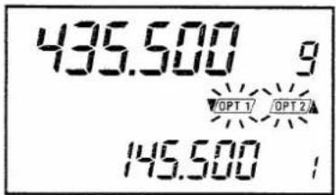
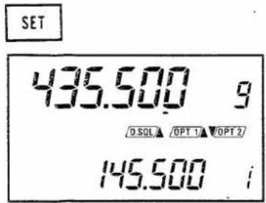
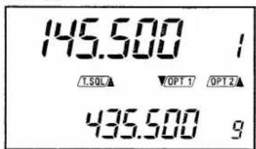
Either "OPT1" or "OPT2" or both appear on the FUNCTION DISPLAY. These indicators show which units are connected in which band.
2) If "D.SQL" or "T.SCL" appear on the FUNCTION DISPLAY, push the [T/DS] SWITCH to turn the unit OFF.
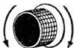
3) Push the [SET] SWITCH several times until "OPT1" or "OPT2" or both blink.
SET
VFO
or
MR
T/DS
435.500 g
▼T.SQL /D.SQL/ OPT 1/▼OPT 2
145.500
4) Rotate the TUNING CONTROL to select which band you require to operate the optional unit in.
- “A” or “▼” alternately appear to the side of “OPT1” or “OPT2” on the FUNCTION DISPLAY.
• “▲” : Installed unit can operate on the MAIN BAND. “▼” : Installed unit can operate the SUB BAND.
5) Push the [VFO] or [MR] SWITCH to return to OPERATING MODE.
6) If both units are installed, push the [T/DS] SWITCH to check which units are being selected.
- The display at left shows that the UT-28 DIGITAL CODE SQUELCH UNIT is connected to the MAIN BAND and the UT-29 TONE SQUELCH UNIT is connected to the SUB BAND, if the UT-28 is installed in the OPTION 1 and UT-29 is installed in the OPTION 2 positions.
10 - 3 UT-28 OPERATION
The UT-28 DIGITAL CODE SQUELCH UNIT has three-memory-channel capability for storing the desired group code numbers which are most often used.
1) Select the UT-28 connected band (MAIN or SUB BAND) with the [SUB] or [M/S] SWITCH.
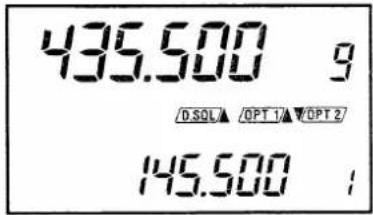
- “Δ” or “▼” shows that the UT-28 is connected to either the MAIN or SUB BAND.
2) Push the [T/DS] SWITCH to access the UT-28.
- “ D.SQL ” appears on the FUNCTION DISPLAY.
- If "T.SQL" appears, the selected unit is the opposite one desired so refer to SECTION 10-2 UT-28 and UT-29 SELECTION and select the unit again.
T/NS
SET
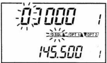
3) Push the [SET] SWITCH.
- A group code appears and “D.SQL” begins blinking on the FUNCTION DISPLAY.
- If "OPT1" or "OPT2" or another indicator begin blinking, the selected band is wrong so push the [VFO] SWITCH and refer to step 1) above and check again.
T/NS
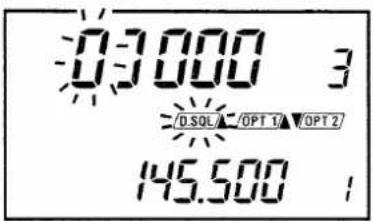
4) Push the [T/DS] SWITCH to select the required group code memory channel.
- 3-group code memory channels are built-in for quick code selection.
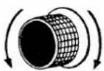
5) Rotate the TUNING CONTROL to set the blinking digit to the desired number.
- Only the blinking digit can be changed.
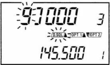
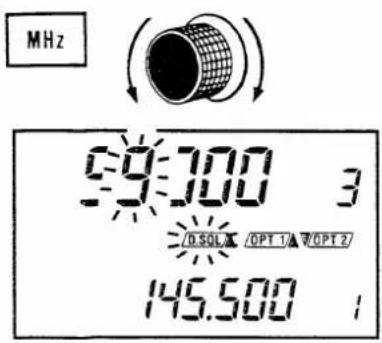
6) Push the [MHz] SWITCH to change the digit of the group code and then rotate the TUNING CONTROL to set the blinking digit to the desired number.
- Repeat the above operation and set the five-digit of the desired group code number.
7) Push the [SET] SWITCH to return to OPERATING MODE. The IC-900A/E is now ready to operate with the UT-28.
T/NS
8) Push the [T/DS] SWITCH to cancel the Digital Code Squelch System.
9) Push the [T/DS] SWITCH again to activate this function with a programmed group code.
10 - 4 UT-29 OPERATION
The UT-29 TONE SQUELCH UNIT has 37 kinds of tone frequencies available and the IC-900A/E can store three of these.
1) Select the UT-29 connected band (MAIN or SUB BAND) with the [SUB] or [M/S] SWITCH.
- “▲” or “▼” shows that the UT-29 is connected to either the MAIN or SUB BAND.
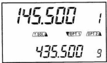
2) Push the [T/DS] SWITCH to access the UT-29.
• " T.SQL " appears on the FUNCTION DISPLAY.
- If " D.SQL" appears, the unit selected is the opposite one desired so refer to SECTION 10-2 UT-28 AND UT-29 SELECTION and select the unit again.
3) Push the [SET] SWITCH.
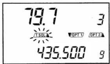
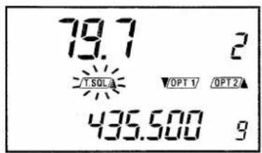
- A tone frequency appears and "T.SQL" begins blinking on the FUNCTION DISPLAY.
- If “OPT 1” or “OPT 2” or another indicator begin blinking, the selected band is wrong so push the [VFO] SWITCH and refer to step 1) above and check again.
T/DS
SET
T/NS
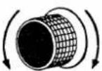
SET
T/DS
4) Push the [T/DS] SWITCH to select the required tone memory channel.
- 3-tone memory channels are built-in for quick code selection.
5) Rotate the TUNING CONTROL to set the blinking digit to the desired number.
6) Push the [SET] SWITCH to return to OPERATING MODE. The IC-900A/E is now ready to operate with the UT-29.
7) Push the [T/DS] SWITCH to cancel the Tone Squelch System.
8) Push the [T/DS] SWITCH again to activate this function with a programmed tone frequency.
11. MAINTENANCE
OPERATING TEMPERATURE NOTE
The BAND UNITS especially may become hot while transmitting for long periods of time.
WARNING: DO NOT allow babies or small children to touch the BAND UNITS during operations.
ADJUSTMENTS
No internal adjustment of the transceiver is required since all variable components have been set correctly at the factory. Misadjusting certain components may damage the transceiver.
CPU MALFUNCTIONS
A variety of apparent problems can be solved by simply resetting the internal CPU in the REMOTE CONTROLLER.
The FUNCTION DISPLAY may occasionally display erroneous information either during operation or when first applying power. This may be due to an external cause such as static electricity.
1) Turn power OFF, wait a few seconds and turn power ON again.
2) If the problem persists, reset the internal CPU according to the following procedures:
CAUTION: After resetting the CPU, all information (memory channels and other settings) must be re-programmed.
- Hold down the [MR] SWITCH and turn power OFF then, turn power ON.
3) The CPU is now reset.
CLEANING
The IC-900A/E REMOTE CONTROLLER will eventually require cleaning. Use a soft cloth with a mild, soapy solution. DO NOT use strong chemicals or cleaning solvents.
■ FUSES
Locate the cause of a blown fuse before replacing the fuse and attempting to operate the IC-900A/E again. The IC-900A/E uses two types of fuses in the DC power cable:
- DC line to INTERFACE UNIT-A : 5A
- DC line to INTERFACE UNIT-B : 15A

12. BLOCK DIAGRAM
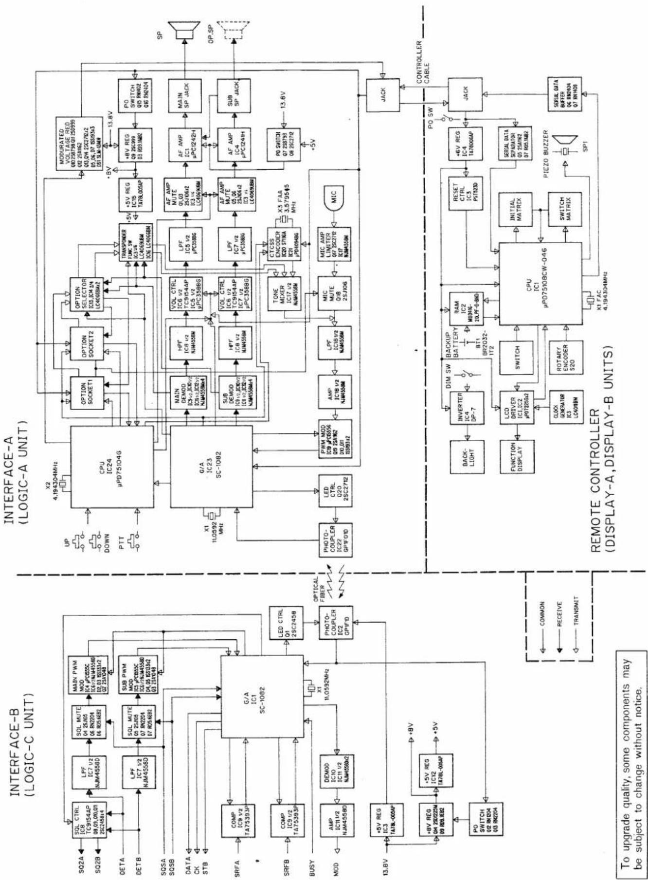
flowchart
graph TD
    subgraph_Interface-B["INTERFACE-B (LOGIC-C UNIT)"]
        A1["SQL CTRL IC8 TC9154AP 09.01.00.01 ZS27456A"] --> B1["LPF IC7 1/2 NJM4558D"]
        B1 --> C1["SQL MUTE 04 25A05 06 PN2024 06 RD56EB2"]
        C1 --> D1["MAIN PWM MOD IC4 PN3555C 02.03 NJM4558E 02.03 RS133A2 02 ZS1048"]
        D1 --> E1["LPF IC7 1/2 NJM4558D"]
        E1 --> F1["SQL MUTE 05 25A05 07 PN2024 07 RD56EB2"]
        F1 --> G1["SUB PWM MOD IC3 PN3555C 02.03 NJM4558E 02.03 RS133A2 02 ZS1048"]
        G1 --> H1["G/A IC1 SC-1082"]
        H1 --> I1["LED CTRL Q1 ZSC245B"]
        I1 --> J1["OPTICAL FIBER"]
        J1 --> K1["Photo-Coupler IC2 GPFFID"]
        K1 --> L1["COMP IC9 1/2 TA75393P"]
        L1 --> M1["SRFA"]
        M1 --> N1["COMP IC9 1/2 TA75393P"]
        N1 --> O1["COMP IC9 1/2 TA75393P"]
        O1 --> P1["COMPS"]
        P1 --> Q1["COMP IC9 1/2 TA75393P"]
        Q1 --> R1["COMP IC9 1/2 TA75393P"]
        R1 --> S1["COMP IC9 1/2 TA75393P"]
        S1 --> T1["COMP IC9 1/2 TA75393P"]
        T1 --> U1["COMP IC9 1/2 TA75393P"]
        U1 --> V1["COMP IC9 1/2 TA75393P"]
        V1 --> W1["COMP IC9 1/2 TA75393P"]
        W1 --> X1["COMP IC9 1/2 TA75393P"]
        X1 --> Y1["COMP IC9 1/2 TA75393P"]
        Y1 --> Z1["COMP IC9 1/2 TA75393P"]
        Z1 --> AA["COMP IC9 1/2 TA75393P"]
        AA --> AB["COMP IC9 1/2 TA75393P"]
        AB --> AC["COMP IC9 1/2 TA75393P"]
        AC --> AD["COMP IC9 1/2 TA75393P"]
        AD --> AE["COMP IC9 1/2 TA75393P"]
        AE --> AF["COMP IC9 1/2 TA75393P"]
        AF --> AG["COMP IC9 1/2 TA75393P"]
        AG --> AH["COMP IC9 1/2 TA75393P"]
        AH --> AI["COMP IC9 1/2 TA75393P"]
        AI --> AJ["COMP IC9 1/2 TA75393P"]
        AJ --> AK["COMP IC9 1/2 TA75393P"]
        AK --> AL["COMP IC9 1/2 TA75393P"]
        AL --> AM["COMP IC9 1/2 TA75393P"]
        AM --> AN["COMP IC9 1/2 TA75393P"]
        AN --> AO["COMP IC9 1/2 TA75393P"]
        AO --> AP["COMP IC9 1/2 TA75393P"]
        AP --> AQ["COMP IC9 1/2 TA75393P"]
        AQ --> AR["COMP IC9 1/2 TA75393P"]
        AR --> AS["COMP IC9 1/2 TA75393P"]
        AS --> AT["COMP IC9 1/2 TA75393P"]
        AT --> AU["COMP IC9 1/2 TA75393P"]
        AU --> AV["COMP IC9 1/2 TA75393P"]
        AV --> AW["COMP IC9 1/2 TA75393P"]
        AW --> AX["COMP IC9 1/2 TA75393P"]
        AX --> AY["COMP IC9 1/2 TA75393P"]
        AY --> AZ["COMP IC9 1/2 TA75393P"]
        AZ --> BA["COMP IC9 1/2 TA75393P"]
        BA --> BB["COMP IC9 1/2 TA75393P"]
        BB --> BC["COMP IC9 1/2 TA75393P"]
        BC --> BD["COMP IC9 1/2 TA75393P"]
        BD --> BE["COMP IC9 1/2 TA75393P"]
        BE --> BF["COMP IC9 1/2 TA75393P"]
        BF --> BG["COMP IC9 1/2 TA75393P"]
        BG --> BH["COMP IC9 1/2 TA75393P"]
        BH --> BI["COMP IC9 1/2 TA75393P"]
        BI --> BJ["COMP IC9 1/2 TA75393P"]
        BJ --> BK["COMP IC9 1/2 TA75393P"]
        BK --> BL["COMP IC9 1/2 TA75393P"]
        BL --> BM["COMP IC9 1/2 TA75393P"]
        BM --> BN["COMP IC9 1/2 TA75393P"]
        BN --> BO["COMP IC9 1/2 TA75393P"]
        BO --> BP["COMP IC9 1/2 TA75393P"]
        BP --> BQ["COMP IC9 1/2 TA75393P"]
        BQ --> BR["COMP IC9 1/2 TA75393P"]
        BR --> BS["COMP IC9 1/2 TA75393P"]
        BS --> BT["COMP IC9 1/2 TA75393P"]
        BT --> BU["COMP IC9 1/2 TA75393P"]
        BU --> BV["COMP IC9 1/2 TA75393P"]
        BV --> BW["COMP IC9 1/2 TA75393P"]
        BW --> BX["COMP IC9 1/2 TA75393P"]
        BX --> BY["COMP IC9 1/2 TA75393P"]
        BY --> BZ["COMP IC9 1/2 TA75393P"]
        BZ --> CA["COMP IC9 1/2 TA75393P"]
        CA --> CB["COMP IC9 1/2 TA75393P"]
        CB --> CC["COMP IC9 1/2 TA75393P"]
        CC --> CD["COMP IC9 1/2 TA75393P"]
        CD --> CE["COMP IC9 1/2 TA75393P"]
        BE --> CF["OPTICAL FIBER"]
    end

    subgraph INTERFACE-A(LOGICA UNIT)
        G/A["CPU IC24 μPD75I04G"] --> HPM["MAIN DEMOD IC8-2J,IC8-4J,IC8-4J,IC8-4J,IC8-4J,IC8-4J,IC8-4J,IC8-4J,IC8-4J,IC8-4J,IC8-4J,IC8-4J,IC8-4J,IC8-4J,IC8-4J,IC8-4J,IC8-4J,IC8-4J,IC6:V,IC6:V,IC6:V,IC6:V,IC6:V,IC6:V,IC6:V,IC6:V,IC6:V,IC6:V,IC6:V,IC6:V,IC6:V,IC6:V,IC6:V,IC6:V,IC6:V,IC6:V,IC6:V,IC6:V,IC6:VS,IC6:VS,IC6:VS,IC6:VS,IC6:VS,IC6:VS,IC6:VS,IC6:VS,IC6:VS,IC6:VS,IC6:VS,IC6:VS,IC6:VS,IC6:VS,IC6:VS,IC6:VS,IC6:VS,IC6:VS,IC6:VS,IC6:VS,IC6:VA,IC6:VA,IC6:VA,IC6:VA,IC6:VA,IC6:VA,IC6:VA,IC6:VA,IC6:VA,IC6:VA,IC6:VA,IC6:VA,IC6:VA,IC6:VA,IC6:VA,IC6:VA,IC6:VA,IC6:VA,IC6:VA,IC6:VA,IC6:SA,K,V,K,V,K,V,K,V,K,V,K,V,K,V,K,V,K,V,K,V,K,V,K,V,K,V,K,V,K,V,K,V,K,V,K,V,K,V,K,V,K,V,K,V,K,V,K,V,K,V,K,V,K,V,K,V,K,V,K,V,K,V,K,V,K,V,K,V,K,V,K,V,K,V,K,V,K,V,K,V,K,V,K,V,K,V,K,V,K,V,K,V,K,V,K,V,K,V,K,V,K,\( +{SV}\text{ REG } \) ICS T478L00SP<br>    end<br><br>    subgraph INTERFACE-B(REMOLE CONTROLLER DISPLAY-A,BUNITS)<br>        CPU [CPU IC"] --> RAM["BMI"] --> RESET["CMT"] --> RESET_CMT
    end

    subgraph INTERFACE-B(REMOLE CONTROLLER DISPLAY-BUNITS)
        CPU_Back["XAM METER OP SLCN"] --> MIC["MIC MUTE QIB QSIJ06"] --> MIC_MUTE_QIB QSIJ06] --> MIC_LIMEQIP_UPQSP_UPQSP_UPQSP_UPQSP_UPQSP_UPQSP_UPQSP_UPQSP_UPQSP_UPQSP_UPQSP_UPQSP_UPQSP_UPQSP_UPQSP_UPQSP_UPQSP_UPQSP_UPQSP_UPQSP_UPQSP_UPQSP_UPQSP_UPQSP_UPQSP_UPQFP_UPQFP_UPQFP_UPQFP_UPQFP_UPQFP_UPQFP_UPQFP_UPQFP_UPQFP_UPQFP_UPQFP_UPQFP_UPQFP_UPQFP_UPQFP_UPQFP_UPQFP_UPQFP_UPQFP_UPQFP_UPQFP_UPQP
    end

    subgraph INTERFACE-B(REMOLE CONTROLLER DISPLAY-BUNITS)
        CPU_Back["XAM METER OP SLCN"] --> RAM_BMI
    end

    subgraph INTERFACE-B(REMOLE CONTROLLER DISPLAY-BUNITS)
        CPU_Back_Back["XAM METER OP SLCN"] --> RAM_BMI
    end

    subgraph INTERFACE-B(REMOLE CONTROLLER DISPLAY-BUNITS)
        CPU_Back_Back_Back["XAM METER OP SLCN"] --> RAM_BMI
    end

    subgraph INTERFACE-B(REMOLE CONTROLLER DISPLAY-BUNITS)
        CPU_Back_Back_Back_Back_Back_Back_Back_Back_Back_Back_Back_Back_Back_Back_Back_Back_Back_Back_Back_Back_Back_Back_Back_Back_Back_Back_Back_Back_Back_Back_Back_Back_Back_Back_Back_Back_Back_Back_Back_Back_Back_Back_Back_Back_Back_Back_Back_Back_Back_Back_Batch
    end

    note bottom of diagram:
    To upgrade quality, some components may be subject to change without notice.
    note top of diagram:
    SQ2A
    SQ2B
    SQSA
    SQSB
    DATA
    CK
    STB
    SRFA
    SRFB
    BUSY
    MOD
    AMP
    ICM
    AMP
    OC
    IM
    PM
    DD
    DD
    DD
    DD
    DD
    DD
    DD
    DD
    DD
    DD
    DD
    DD
    DD
    DD
    DD
    DD
    DD
    DD
    DD
    DD
    DD
    DD
    DD
    DD
    DD
    DD
    DD
    DD
    DD
    DD
    DD
    DD
    DD
    DD

    note bottom of diagram:
    SQ2A <--> note bottom of diagram:
    SQ2B <--> note bottom of diagram:
    SQSA <--> note bottom of diagram:
    SQSB <--> note bottom of diagram:
    DATA <--> note bottom of diagram:
    CK <--> note bottom of diagram:
    STB <--> note bottom of diagram:
    SRFA <--> note bottom of diagram:
    SRFB <--> note bottom of diagram:
    BUSY <--> note bottom of diagram:
    MOD <--> note bottom of diagram:
    AMP <--> AMP <--> AMP <--> AMP <--> AMP <--> AMP <--> AMP <--> AMP <--> AMP <--> AMP <--> AMP <--> AMP <--> AMP <--> AMP <--> AMP <--> AMP <--> AMP <--> AMP <--> AMP <--> AMP <--> AMP <--> AMP <--> AMP <--> AMP <--> AMP <--> AMP <-> AMP <-> AMP <-> AMP <-> AMP <-> AMP <-> AMP <-> AMP <-> AMP <-> AMP <-> AMP <-> AMP <-> AMP <-> AMP <-> AMP <-> AMP <-> AMP <-> AMP <-> AMP <-> AMP <-> AMP <-> AMP <-> AMP <-> AMP <-> AMP <-> AMP < --> AMP <-> AMP <-> AMP <-> AMP <-> AMP <-> AMP <-> AMP <-> AMP <-> AMP <-> AMP <-> AMP <-> AMP <-> AMP <-> AMP <-> AMP <-> AMP <-> AMP <-> AMP <-> AMP<->Amp<->Amp<->Amp<->Amp<->Amp<->Amp<->Amp<->Amp<->Amp<->Amp<->Amp<->Amp<->Amp<->Amp<->Amp<->Amp<->Amp<->Amp<->Amp<->Amp<->Amp<->Amp<->Amp<->Amp<->Amp<->Anp<->Amp<->Amp<->Amp<->Amp<->Amp<->Amp<->Amp<->Amp<->Amp<->Amp<->Amp<->Amp<->Amp<->Amp<->Amp<->Amp<->Amp<->Amp<->Amp<->Amp<->Amp<->Amp<->Amp<->Amp<->Amf<<=>>>>

    %% Note to upgrade quality, some components may be subject to change without notice.

    %% Note to upgrade quality, some components may be subject to change without notice.

    %% Note to upgrade quality, some components may be subject to change without notice.

    %% Note to upgrade quality, some components may be subject to change without notice.

    %% Note to upgrade quality, some components may be subject to change without notice.

    %% Note to upgrade quality, some components may be subject to change without notice.

    %% Note to upgrade quality, some dimensions may be subject to change without notice.

    %% Note to upgrade quality, some dimensions may be subject to change without notice.

    %% Note to upgrade quality, some dimensions may be subject to change without notice.

    %% Note to upgrade quality, some dimensions may be subject to change without notice.

    %% Note to upgrade quality, some dimensions may be subject to change without notice.

    %% Note to upgrade quality, some dimensions may be subject to change without notice.
Count on us!
natural_image
Completely black image with no visible content, text, or symbols.- FOREWORD
- FEATURES
- SELECTABLE ONE TO SIX BAND OPERATION
- OPTICAL FIBER CABLE
- FULL DUPLEX CAPABILITY
- A VARIETY OF ADVANCED FUNCTIONS AVAILABLE
- MEMORY CHANNEL CAPABILITY
- SEPARATE USER-PROGRAMMED TUNING STEPS
- OPTIONAL UNIT OPERATIONS
- TABLE OF CONTENTS
- CONSTRUCTION
- CONSTRUCTION OF THE IC-900 MULTI-BANDER SYSTEM
- UNPACKING
- INSTALLATIONS
- - 1 UNIT INSTALLATIONS
- CAUTION:
- 4-2 UNIT CONNECTIONS
- POWER SOURCE CONNECTION
- ●Cable separator socket crimping
- INTERFACE UNIT-A INSTALLATION
- INTERFACE UNIT-B INSTALLATION
- NOTE:
- INTERFACE UNIT-B AND BAND UNIT
- OPTICAL FIBER CABLE
- CAUTIONS:
- - 3 OTHERS
- ANTENNA LOCATION
- DUPLEXER
- COAXIAL CABLE
- CONNECTOR INSTALLATION
- PRE-OPERATION
- CONFIRMATION OF INSTALLATION
- POWER ON
- - When the correct connection is made
- BASIC OPERATIONS
- - 1 RECEIVING
- - 2 TRANSMITTING
- ● Repeater operation
- CONTROL FUNCTIONS
- 7-1 REMOTE CONTROLLER
- - 2 FUNCTION DISPLAY
- FUNCTION OPERATIONS
- 8-1 MEMORY OPERATIONS
- MEMORY READING
- MEMORY WRITING
- MEMORY TRANSFERS
- 8-2 SCAN OPERATIONS
- PROGRAMMED SCAN
- MEMORY SCAN
- SKIP CHANNEL
- 8-3 CALL CHANNEL OPERATIONS
- CALL CHANNEL READ
- PROGRAMMING
- - 4 BEEP TONE ON AND OFF
- SET MODE
- - 2 TUNING STEP (A)
- - 3 TUNING STEP (B)
- - 4 OFFSET WRITE
- - 5 SUBAUDIBLE TONE FREQUENCY
- 9-6 SCAN EDGES
- - 7 BAND UNIT
- OPTIONAL SQUELCH UNIT
- - 1 UT-28 AND UT-29 INSTALLATION
- - 2 UT-28 AND UT-29 SELECTION
- - 3 UT-28 OPERATION
- - 4 UT-29 OPERATION
- MAINTENANCE
- OPERATING TEMPERATURE NOTE
- ADJUSTMENTS
- CPU MALFUNCTIONS
- CLEANING
- ■ FUSES
- BLOCK DIAGRAM
Marke : ICOM
Modell : IC-900A
Kategorie : Empfänger