
IC-EX310 - Empfänger ICOM - Kostenlose Bedienungsanleitung
Finden Sie kostenlos die Bedienungsanleitung des Geräts IC-EX310 ICOM als PDF.


| Produkttyp | Sprachsynthesizer-Einheit |
| Kompatible Transceiver | IC-751, IC-271A/E, IC-471A/E (ICOM) |
| Stromversorgung | Über den Transceiver (kein externes Netzteil erforderlich) |
| Funktion | Sprachausgabe der eingestellten Frequenz in Englisch |
| Lautstärkeeinstellung | Über Potentiometer R16 auf der Platine |
| Sprechgeschwindigkeit | Schneller durch Durchtrennen der Drahtbrücke W1 |
| Frequenzanzeige Beispiele | "14.231,5 MHz" → "ONE FOUR POINT TWO THREE ONE FIVE MHz" |
| Installation | Einbau in den Transceiver, Anschluss an LOGIC-Einheit (J12 oder J10) |
| Sicherheitshinweis | Vor dem Einbau Netzstecker des Transceivers ziehen |
| Lieferumfang | Einheit, Schrauben, Anschlusskabel |
| Garantie | Keine Angabe, übliche ICOM-Garantie |
| Sprache der Sprachausgabe | Englisch (fest) |
| Zusätzliche Hinweise | Die Einheit ist optional und nur für die genannten Modelle geeignet |
| Bedienung | Aktivierung über SPEECH-Taste (IC-751) oder DIAL LOCK AND SPEECH-Taste (IC-271A/E, IC-471A/E) |
Häufig gestellte Fragen - IC-EX310 ICOM
Benutzerfragen zu IC-EX310 ICOM
0 Frage zu diesem Gerät. Beantworten Sie die, die Sie kennen, oder stellen Sie Ihre eigene.
Eine neue Frage zu diesem Gerät stellen
Laden Sie die Anleitung für Ihr Empfänger kostenlos im PDF-Format! Finden Sie Ihr Handbuch IC-EX310 - ICOM und nehmen Sie Ihr elektronisches Gerät wieder in die Hand. Auf dieser Seite sind alle Dokumente veröffentlicht, die für die Verwendung Ihres Geräts notwendig sind. IC-EX310 von der Marke ICOM.
BEDIENUNGSANLEITUNG IC-EX310 ICOM

ICOM
IC-EX310
VOICE SYNTHESIZER UNIT
INSTRUCTION MANUAL
This instruction manual gives descriptions and installation instructions for the optional voice synthesizer unit for ICOM transceivers IC-751, IC-271A/E and IC-471A/E. It also provides information you need while using them. Please read all the instructions carefully before installation so you will get maximum performance and full value from each set.
PREPARATION
Before performing any work on the set, make sure that the power cord is unplugged from the transceiver. Remove the top and bottom covers by unscrewing the six screws each on the top and bottom, and the three screws on each side, while taking care not to damage the internal speaker, and unplug its connector.
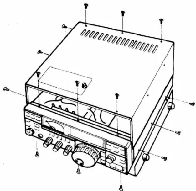
ASSEMBLY PROCEDURE
FOR IC-751
-
Turn the transceiver upside down.
-
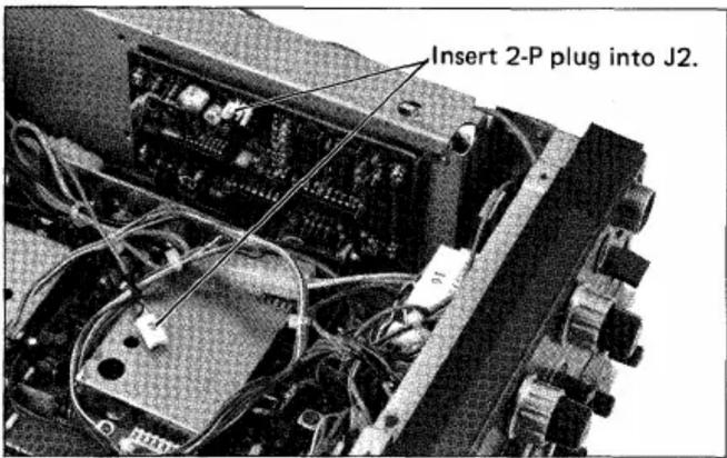
Insert 2-P plug as shown in the photo into J2 of this unit, then install the unit with the supplied four screws as shown in the photo.
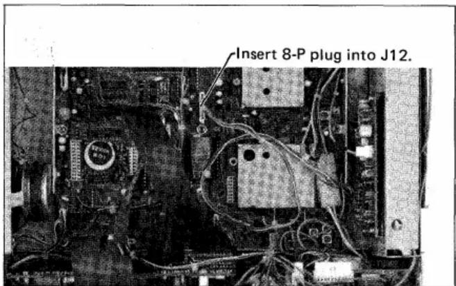
- Plug 8-P plug of this unit into J12 of the LOGIC unit.
- Adjust its volume and speaking speed if necessary. (Described later.)
- Connect internal speaker connector, then replace the top and bottom covers of the set.
FOR IC-271A/E AND IC-471A/E
- Insert 2-P plug as shown in the photo into J2 of this unit, then install the unit with the supplied four screws as shown in the photo.
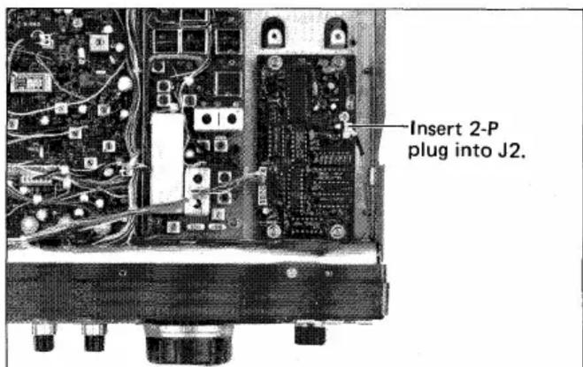
- Run the cord with 8-P connector from the unit along the front panel, then pass it through the slot between the front panel and chassis located around the meter hood, to the bottom side.
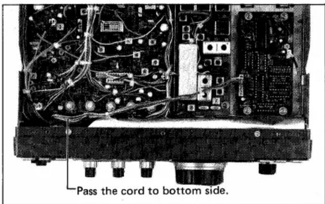
- Turn the set upside down. Then insert the 8-P connector into J10 of the LOGIC unit.
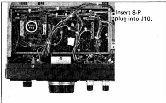
-
Adjust its volume and speaking speed if necessary. (Described later.)
-
Connect internal speaker connector, then replace the top and bottom covers of the set.
ADJUSTMENT
-
Adjust the volume of the speech and speaking speed before the top and bottom covers are replaced, if necessary.
-
Connect a power source and turn on the power switch.
-
By pushing the SPEECH switch (IC-271A/E and IC-471A/E: the DIAL LOCK AND SPEECH switch), the unit is actuated and announces the displayed frequency in English.
-
The volume of the announcement is adjustable with R16 in the unit. Adjust it for a comfortable level.
-
By cutting W1 jumper wire, the speaking speed becomes faster.
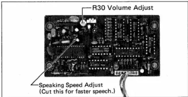
- When finished with the adjustment, replace the top and bottom covers of the set.
HOW THE VOICE SYNTHESIZER UNIT WORKS
-
When "14.231.5MHz" is displayed; "ONE FOUR POINT TWO THREE ONE FIVE MHz" will be heard.
-
When "145.280.0MHz" is displayed; "ONE FOUR FIVE POINT TWO EIGHT ZERO ZERO MHz" will be heard.
-
When a blanked memory channel is selected; "POINT MHz" will be heard.
-
When the TONE SELECT button is pushed and TONE NUMBER "16" is displayed (IC-271A/E only); "POINT ONE SIX MHz" will be heard.
-
When the OFFSET WRITE button is pushed and offset frequency "05.000." is displayed; "ZERO FIVE POINT ZERO ZERO ZERO MHz" will be heard.
ICOM INCORPORATED
1-6-19, KAMIKURATSUKURI HIRANO-KU, OSAKA JAPAN
Marke : ICOM
Modell : IC-EX310
Kategorie : Empfänger