
IC-1200A - Empfänger ICOM - Kostenlose Bedienungsanleitung
Finden Sie kostenlos die Bedienungsanleitung des Geräts IC-1200A ICOM als PDF.


| Produkttyp | 1200-MHz-FM-Transceiver (Empfänger und Sender) |
| Marke | ICOM |
| Modell | IC-1200A |
| Frequenzbereich | 1240 - 1300 MHz |
| Frequenzauflösung | 10 oder 20 kHz (IC-1200A) / 12,5 oder 25 kHz (IC-1200E) |
| Speicherkanäle | 21 |
| Stromversorgung | 13,8 V DC ±15% (negative Masse) |
| Stromaufnahme Senden (HIGH) | max. 5,5 A |
| Stromaufnahme Senden (LOW) | ca. 2,5 A |
| Stromaufnahme Empfang (max. Audio) | ca. 900 mA |
| Stromaufnahme Empfang (stummgeschaltet) | ca. 600 mA |
| Antennenimpedanz | 50 Ω (Typ-N-Stecker) |
| Abmessungen (B x H x T) | 140 x 40 x 196 mm (mit Vorsprüngen 211 mm) |
| Gewicht | 1,5 kg |
| Sendeleistung | HIGH 10 W, LOW 1 W |
| Modulationsart | F3 (F2 mit optionalem UT-28) |
| Empfangssystem | Dreifach-Superheterodyn |
| Zwischenfrequenzen | 136,6 MHz / 17,2 MHz / 455 kHz |
| Empfindlichkeit (12 dB SINAD) | <0,22 μV |
| Audioausgangsleistung | >2,4 W an 8 Ω |
| Funktionen | AFC, Auto-Dimmer, 21 Speicher, Dual-Scan, subaudibler Ton (38 Töne) |
| Optionale Rauschsperren | UT-28 (Digitalcode), UT-29 (Ton) |
| Reinigung | Weiches Tuch mit milder Seifenlösung |
| Sicherung | 10 A im Stromkabel |
| Betriebstemperatur | -10 °C bis +60 °C |
Häufig gestellte Fragen - IC-1200A ICOM
Benutzerfragen zu IC-1200A ICOM
0 Frage zu diesem Gerät. Beantworten Sie die, die Sie kennen, oder stellen Sie Ihre eigene.
Eine neue Frage zu diesem Gerät stellen
Laden Sie die Anleitung für Ihr Empfänger kostenlos im PDF-Format! Finden Sie Ihr Handbuch IC-1200A - ICOM und nehmen Sie Ihr elektronisches Gerät wieder in die Hand. Auf dieser Seite sind alle Dokumente veröffentlicht, die für die Verwendung Ihres Geräts notwendig sind. IC-1200A von der Marke ICOM.
BEDIENUNGSANLEITUNG IC-1200A ICOM
IC-1200A/E
1200MHz FM TRANSCEIVER
INSTRUCTION MANUAL
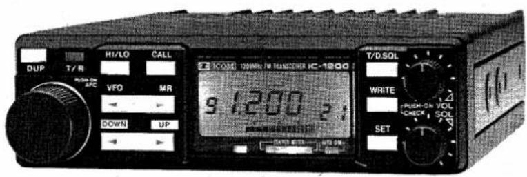
TABLE OF CONTENTS
SECTION 1 SPECIFICATIONS.... 1
SECTION 2 FEATURES 2
SECTION 3 CONTROL FUNCTIONS.... 3
SECTION 4 INSTALLATIONS 8
SECTION 5 GENERAL OPERATIONS 10
5-1 RECEIVING 10
5 - 2 FREQUENCY SELECTING.... 11
5-3 TRANSMITTING 12
5-4 AFC FUNCTION 12
SECTION 6 FUNCTION OPERATIONS.... 13
6 - 1 MEMORY OPERATIONS .... 13
6-2 SCAN OPERATIONS 14
6-3 DUPLEX OPERATIONS.... 16
6 - 4 CALL CHANNEL OPERATIONS.... 18
SECTION 7 MISCELLANEOUS FUNCTIONS ..... 19
7 - 1 MICROPHONE.... 19
7 - 2 BACKUP BATTERY.... 19
7 - 3 RESETTING THE INTERNAL CPU ..... 19
7 - 4 OPTIONAL UNITS. 20
SECTION 8 INSIDE VIEWS 24
SECTION 9 MAINTENANCE 25
SECTION 10 BLOCK DIAGRAM 27
SECTION 11 OPTIONS 28
GENERAL
| Frequency coverage | : 1240 ~ 1300MHz | ||
| Frequency resolution | : IC-1200A 10 or 20kHz (programmable)IC-1200E 12.5 or 25kHz (programmable) | ||
| Frequency control | : CPU based 5kHz (or 6.25kHz) step digital PLL synthesizerSimplex and semi-duplex capability (programmable offset) | ||
| Memory channels | : 21 channels | ||
| Usable temperature range | :-10°C ~ +60°C (+14°F ~ +140°F) | ||
| Power supply requirement | : 13.8V DC ±15% (negative ground)AC power supply is available for AC operation. | ||
| Current drain (at 13.8V DC) | : Transmit | ||
| HIGH (10W) | Maximum | 5.5A | |
| LOW (1W) | Approx. | 2.5A | |
| Receive | |||
| Max. audio output | Approx. | 900mA | |
| Squelched | Approx. | 600mA | |
| Antenna impedance | : 50Ω unbalanced | ||
| Dimensions | : 140(140)mm(W) x 40(40)mm(H) x 196(211)mm(D) | ||
| Bracketed values include projections. | |||
| Weight | : 1.5kg | ||
■ TRANSMITTER
| Output power | : HIGH 10W LOW 1W |
| Emission mode | : F3 (F2 when operating with an optional UT-28) |
| Modulation system | : Variable reactance frequency modulation |
| Max. frequency deviation | : ±5.0kHz |
| Spurious emission | : More than 50dB below carrier with high output powerMore than 40dB below carrier with low output power |
| Microphone | : 600Ω electret condenser with push-to-talk and scanning switches (IC-1200E: 1750Hz tone call switch) |
RECEIVER
| Receive system | : Triple-conversion superheterodyne |
| Modulation acceptance | : FM |
| Intermediate frequencies | : 1st 136.6MHz 2nd 17.2MHz 3rd 455kHz |
| Selectivity | : More than 15.0kHz at -6dBLess than 30.0kHz at -60dB |
| Sensitivity | : Less than 0.22μV for 12dB SINAD |
| Audio output | : More than 2.4W at 10% distortion with 8Ω load |
| Audio output impedance | : 4~8Ω |
* All stated specifications are approximate and subject to change without notice or obligation.
SECTION 2 FEATURES
| ●AFC FUNCTION | The need to consider frequency drift is over with the IC-1200A/E since the transceiver incorporates ICOM's AFC (Automatic Frequency Control) function. AFC automatically and conveniently adjusts the frequency the IC-1200A/E receives to the frequency of the transmitting station. |
| ●COMPACT AND HIGH OUTPUT POWER | Smaller and more compact than many conventional automobile transceivers, the IC-1200A/E still provides 10W of powerful output on any frequency in the 1200MHz band. |
| ●SIMPLE PANEL DESIGN | Even with so many sophisticated functions available, the transceiver front panel layout is extremely simple, making the IC-1200A/E a mobile unit that is both versatile in performance and safe to use while driving. |
| ●AUTOMATIC DIMMER CIRCUIT | A built-in light sensor automatically adjusts a dimmer circuit to control the backlighting of the LCD READOUT. This feature is convenient for reducing eye fatigue during night operation. |
| ●21 MEMORY CHANNELS | The IC-1200A/E introduces a large capacity memory with 21 fully programmable memory channels, placing a variety of communications functions at the fingertips of the driver. |
| ●DUAL SCANNING FUNCTIONS | ● FREQUENCY SCAN: Searches the entire band continuously with frequency increments specified by the operator. ● MEMORY SCAN: Continuously checks all memory channels. |
| ●SUBAUDIBLE TONE ENCODER | The IC-1200A/E incorporates 38 different subaudible tones, ensuring maximum communications coverage by allowing full access to all local repeaters. |
| ●SQUELCH OPTIONS | The UT-28 and UT-29 are two new optional units specially designed for the IC-1200A/E and are ideal for handling the crowded band conditions found in many locations. ● UT-28 DIGITAL CODE SQUELCH UNIT: The UT-28 incorporates a system of digital coding and decoding, that allows a “personalized” squelch to be programmed using 1 of 100,000 different code numbers. ● UT-29 TONE SQUELCH UNIT: The UT-29 is a subaudible tone encoder/decoder that can be installed as an alternative to the UT-28 Digital Code Squelch Unit. |
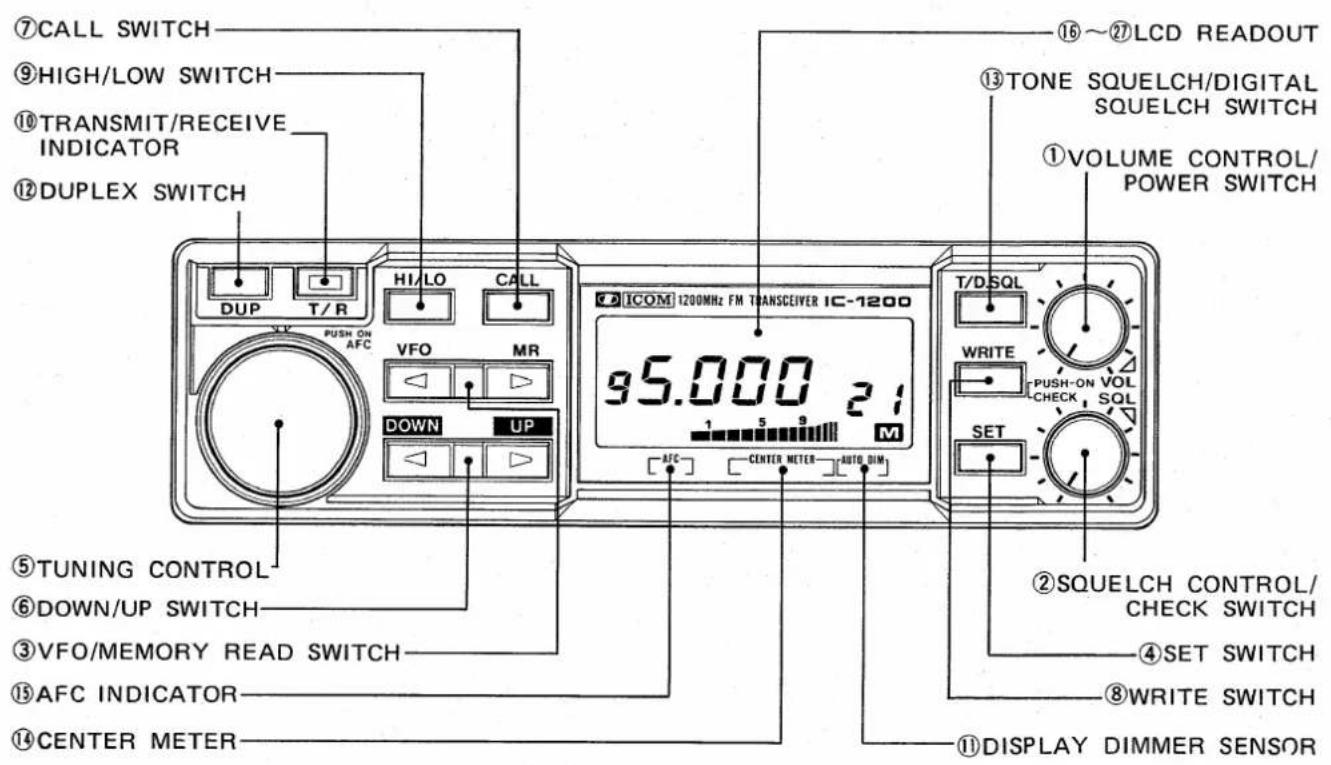
■ FRONT PANEL
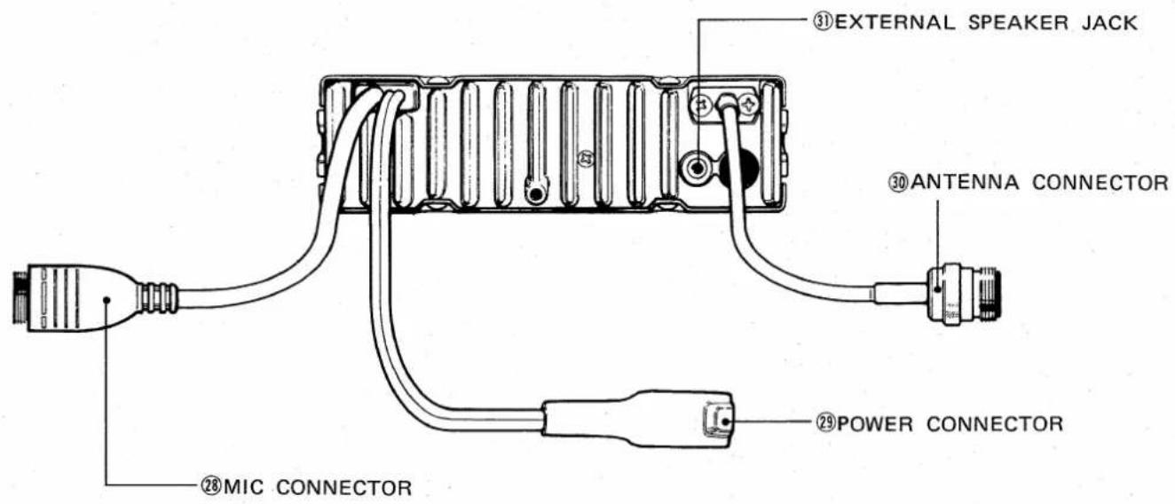
■ REAR PANEL
| 1 VOLUME CONTROL/POWER SWITCH [VOL/PWR] | Push to turn the power ON and OFF. Turn clockwise to increase the audio level. |
| 2 SQUELCH CONTROL/CHECK SWITCH [SQL/CHK] | The squelch circuit quiets noise from the transceiver while no signals are being received.A second feature is the CHECK function which monitors transmit frequency during Duplex operation while this switch is pushed.Refer to pp. 16~17 DUPLEX PROGRAMMING. |
| 3 VFO/MEMORY READ SWITCH [VFO/MR] | Push to select either VFO mode or MEMORY mode. Refer to p. 11 and p. 13. |
| 4 SET SWITCH [SET] | In VFO mode, push the [SET] SWITCH repeatedly to change the following set modes:Subaudible tone encoder (p. 17)Offset frequency (p. 16)Tuning step increment (p. 11)MHz step increment (p. 11)VFO modeIn MEMORY mode, push the [SET] SWITCH to turn the memory skip function ON and OFF. Refer to p. 15. |
| 5 TUNING CONTROL | Controls digits on the LCD READOUT for operating frequencies, offset frequencies, step increments, memory channels, etc. Also controls AFC function ON/OFF and frequency shift. |
| 6 DOWN/UP SWITCH [DOWN/UP] | This switch operates differently depending on the setting of the [VFO/MR] SWITCH.In VFO mode, push to change the selected operating frequency in MHz step increments.In MEMORY mode, push to change the selected memory channels. |
| 7 CALL SWITCH [CALL] | Push to call the memory channel 21 (call channel) and cancel alternately. Refer to p. 18. |
| 8 WRITE SWITCH [WRITE] | In VFO mode, push to store the displayed frequency on the LCD READOUT in the displayed memory channel. Refer to p. 13.In MEMORY mode, push to transfer the contents of the selected memory channel to the VFO. Refer to p. 14. |
| 9 HIGH/LOW SWITCH [HI/LO] | Push to change HIGH (10W) and LOW (1W) transmit output power. “LOW” appears on the LCD READOUT when LOW power is selected. |
| 10 TRANSMIT/RECEIVE INDICATOR [T/R] | Indicates whether the IC-1200A/E is in transmit or receive mode. The indicator is red while transmitting and green while receiving with the squelch circuit open. The indicator is OFF when the squelch circuit is closed and the receiver is muted. |
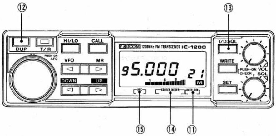
⑪ DISPLAY DIMMER SENSOR
⑫ DUPLEX SWITCH [DUP]
NOTE: Bracketed values show offset frequencies for the the IC-1200E.
⑬ TONE SQUELCH/ DIGITAL SQUELCH SWITCH [T/D.SQL]
⑭ CENTER METER
⑮ AFC INDICATOR
Measures ambient light and controls the dimmer circuit which varies the intensity of the LCD READOUT backlighting.
Push to select Simplex or Duplex operation:
- The transmit frequency is lower than the receive frequency by 12MHz (35MHz) or by the programmed offset when "DUP—" appears on the LCD READOUT.
- The transmit frequency is higher than the receive frequency by 12MHz (35MHz) or by the programmed offset when "DUP+" appears on the LCD READOUT.
- When neither "DUP—" nor "DUP+" appear on the LCD READ-OUT the IC-1200A/E is in Simplex mode. The transmit and receive frequencies are equal at this time.
This switch turns ON and OFF the optional squelch systems:
• TONE SQUELCH SYSTEM
When activated, "TONE" and "D.SQL" appear on the LCD READOUT. Push the [SET] SWITCH to program the desired subaudible tone numbers. Refer to p. 21.
• DIGITAL CODE SQUELCH SYSTEM
When activated, "D.SQL" appears on the LCD READOUT. Push the [SET] SWITCH to program the desired group code. Refer to p. 20.
NOTE: This switch has no function when neither option is installed.
Indicates if another station's transmitting frequency is higher or lower or the same as the IC-1200A/E's receive frequency. Refer to p. 10.
Lights up when the AFC function is activated. Refer to p. 12.
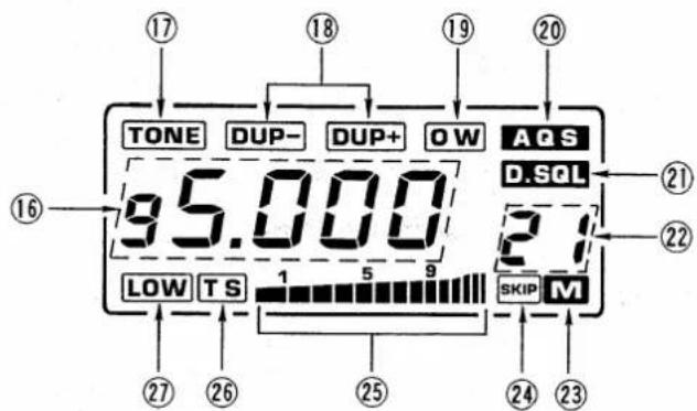
⑯ FREQUENCY INDICATOR
Shows operating frequencies, step increments, group codes etc. Refer to items ⑰~⑳.
The decimal point disappears when the AFC function is activated.
⑰ SUBAUDIBLE TONE INDICATOR "TONE"
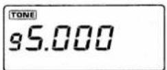
Appears when the subaudible tone encoder is activated. Also appears when the optional UT-29 TONE SQUELCH UNIT is activated. Refer to p. 17 and p. 22.
⑱ DUPLEX MODE INDICATORS "DUP-, DUP+"
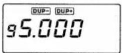
Appear while the IC-1200A/E is in Duplex mode (the transmit frequency is different from the receive frequency). Both indicators disappear while operating in Simplex mode. Refer to p. 16.
⑲ OFFSET WRITE INDICATOR "OW"
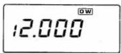
Flashes when the IC-1200A/E is ready to have the transmit offset programmed for duplex operation. Refer to p. 16.
⑳ GROUP CODE INDICATOR "AQS"
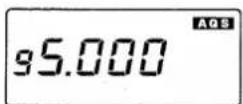
Flashes when the IC-1200A/E is ready to have the group code programmed when using the optional UT-28 DIGITAL CODE SQUELCH UNIT. Refer to p. 20.
②1 SQUELCH SYSTEM INDICATOR "D.SQL"
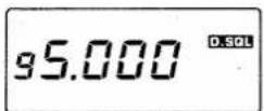
Appears when either the optional tone squelch or optional digital code squelch system is activated. Flashes with the "TONE" INDICATOR when the IC-1200A/E is ready to have the subaudible tone number for the tone squelch programmed. Refer to p. 20 or p. 21.
②2 MEMORY CHANNEL NUMBER
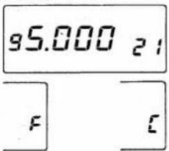
This area displays various symbols:
a) Memory channel numbers "1" to "21".
b) Offset programming symbol "F" or "P".
c) Call channel symbol "C".
d) Subaudible tone memory channel numbers "1", "2" or "3". (IC-1200A only)
②3 MEMORY MODE INDICATOR "M"
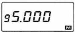
Appears when MEMORY mode is selected with the [VFO/MR] SWITCH. Refer to p. 13.
②4 MEMORY CHANNEL SKIP INDICATOR "SKIP"
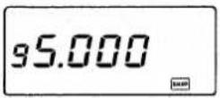
Appears when a particular memory channel has been programmed with the [SET] SWITCH to be excluded from the memory scan operation. Refer to p. 15.
⑳ "S/RF" INDICATOR
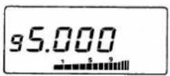
In receive mode this indicator operates as an S-meter, showing the receive signal level. In transmit mode, the relative output power of the transmitter is indicated as follows:
- LOW power : 5 segments appear.
- HIGH power : All segments appear.
②6 TUNING STEP INDICATOR "TS"
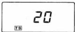
Flashes when the IC-1200A/E is ready for programming of the tuning or MHz step increment. Turn the TUNING CONTROL to select a desired step size. Refer to p. 11.
⑳ OUTPUT POWER INDICATOR "LOW"
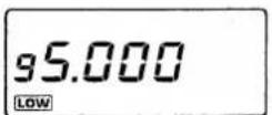
Appears when LOW power is selected with the [HI/LO] SWITCH. Refer to p. 12.
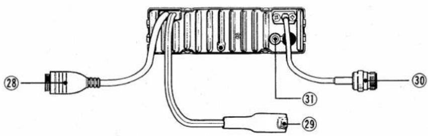
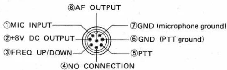
⑳ MIC CONNECTOR
Connect the supplied microphone to this connector. Refer to p. 8 (Outside view)
⑲ POWER CONNECTOR
Connect 13.8V DC ±15% from a stable power source to this connector. Refer to p. 8.
③0 ANTENNA CONNECTOR
Connect a 50Ω antenna with a Type-N connector on the feedline to this connector. Refer to p. 9.
③1 EXTERNAL SPEAKER JACK
Connect a 4 \~ 8Ω speaker to this jack, if required. Connecting the external speaker automatically disconnects the internal speaker.
SECTION 4 INSTALLATIONS
Suitable locations where the transceiver may be installed.
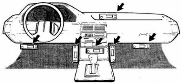
natural_image
Technical diagram of a vehicle interior showing dashboard, steering wheel, and control panel (no text or labels)AVOID mounting the transceiver where:
a) Hot or cold air can blow directly on the unit.
b) Normal operation of the vehicle may be hindered.
c) Excessive vibrations are present.
natural_image
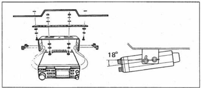
Technical line drawing of a mechanical device with two views: top shows a mounted device, bottom shows a cylindrical device with a 18° angle indicator (no text or symbols present)Securely mount the transceiver with the supplied bracket to minimize vibrations.
The installation angle of the IC-1200A/E can be varied by approximately 18^ . Adjust the angle for the clearest view of the transceiver.
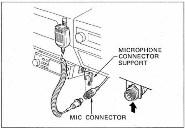
To protect the mic connector cable from damage, the MIC CONNECTOR MUST BE attached to the microphone connector support.
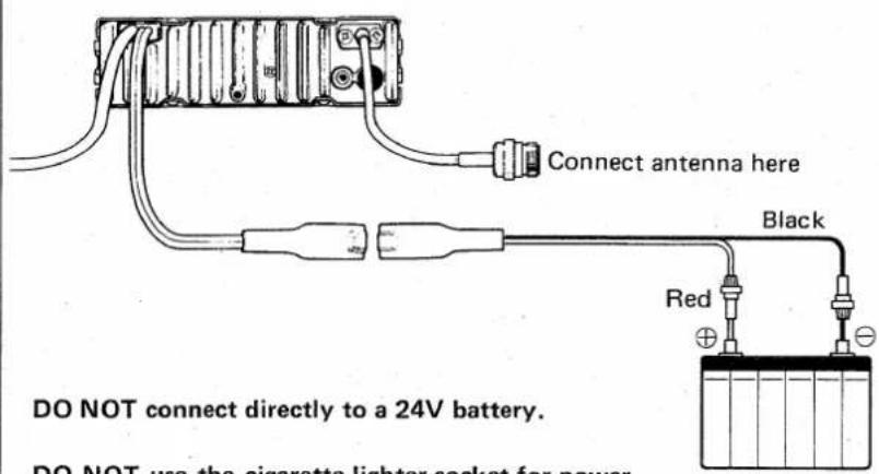
DO NOT use the cigarette lighter socket for power connections.
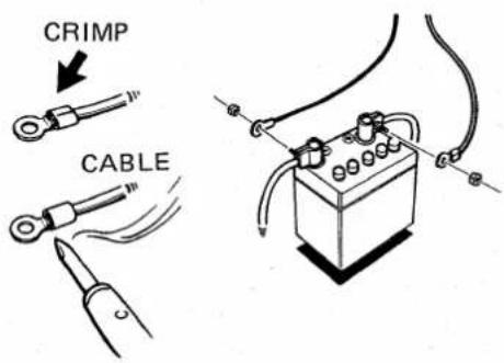
To prevent the voltage from dropping, solder or crimp the cable lag when connecting the power cable to the battery.
- ANTENNA
Transceiver performance largely depends on the quality of the antenna used. Select a high-quality antenna and use it as recommended by the manufacturer.
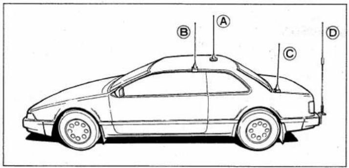
●TYPE-N CONNECTOR INSTALLATION
A: Roof-mount antenna
- Best location for a good radiation pattern. - Drill a hole in the roof, or use a magnetic antenna base.
B: Gutter-mount antenna
C: Trunk-mount antenna
D: Bumper-mount antenna
- Best location for longer antennas.
A TYPE-N connector should be used on the feedline to minimize power loss at UHF frequencies. Follow the instructions below for best results when installing the connector.
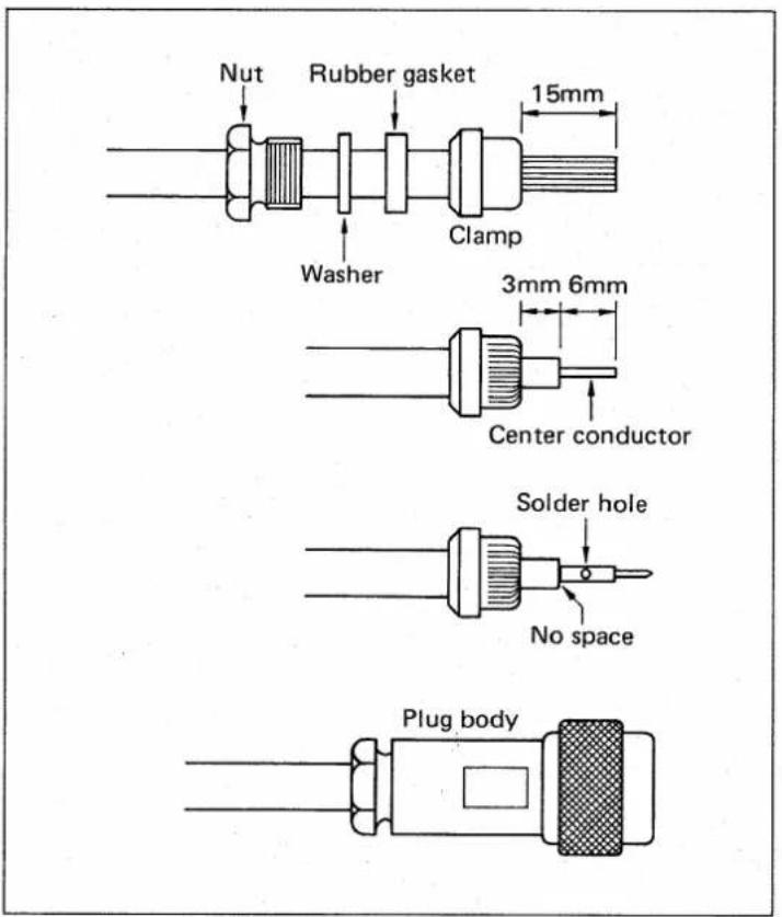
●BASE STATION USE
1) Slide the nut, washer, and rubber gasket over the coaxial cable and cut the end of the cable evenly.
2) Cut and remove 15mm of the outer vinyl jacket, and fold the braid back over the clamp. The clamp end should be flush with the end of the vinyl jacket. Evenly trim the braid ends.
Cut and remove 6mm of the dielectric (the center conductor insulation).
3) Soft-solder the center conductor. Install a center conductor pin and solder it.
4) Carefully slide the plug body into place aligning the center conductor pin on the cable with the hole in the insulator inside the plug body.
Complete the assembly by screwing the nut into the plug body.
When using the IC-1200A/E as a base station, be careful of the following points:
• POWER SUPPLY
Use a 13.8V power supply with more than 5.5A. The optional PS-45 AC POWER SUPPLY is available and can be used with an optional OPC-102 cable.
• COAXIAL CABLE
With a coaxial cable the strength of 1200MHz band signals diminishes, so be sure to use a 50Ω coaxial cable as short and thick as possible.
5 - 1 RECEIVING
1) Push [VOL/PWR] CONTROL.

2) Adjust volume level.

3) Adjust squelch level.
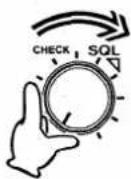
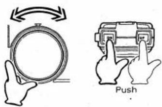
4) Select operating frequency.
5) CENTER METER.
| CONTROL | INITIAL SETTINGS |
| VOL/PWR | Counterclockwise |
| SQL/CHK | Counterclockwise |
1) Push the [VOL/PWR] CONTROL to turn ON the power.
- The green [T/R] INDICATOR lights and the LCD READOUT displays the frequency and memory channel number last used.
2) Turn the [VOL/PWR] CONTROL clockwise until an adequate sound level is obtained.
3) Slowly turn the [SQL/CHK] CONTROL clockwise until the received noise is quieted.
- Make this setting only on a vacant frequency (no received signal).
• The green [T/R] INDICATOR goes out.
- All sound from the speaker is muted until a signal is received when the squelch is in this setting.
4) Select the desired operating frequency by using the TUNING CONTROL or the [UP] or [DN] SWITCH on the microphone.
- If the letter "M" appears on the LCD READOUT below the memory channel number, push the [VFO] side of the [VFO/MR] SWITCH to clear MEMORY mode.
- When a signal is received, the green [T/R] INDICATOR lights, the "S/RF" INDICATOR displays the signal strength on the LCD READOUT and audio is heard from the speaker.
5) Shows the frequency drift of the transmitting stations as follows:
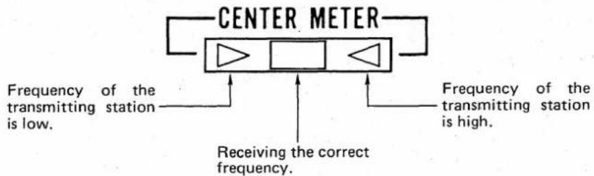
5 - 2 FREQUENCY SELECTING
1) Select VFO mode.
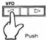
2) Set tuning step increment.
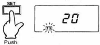
3) Set MHz step increment.
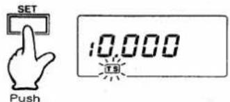
4) Select VFO mode again.
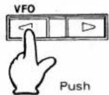
5) Select MHz range.
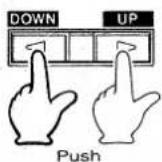
6) Select frequency.
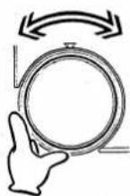
7) Select frequency using microphone.
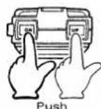
1) Push the [VFO] side of the [VFO/MR] SWITCH.
2) Push the [SET] SWITCH repeatedly until the "TS" INDICATOR flashes and the tuning step increment appears. Turn the TUNING CONTROL to choose the tuning step increment.
- The programmed tuning step increments are as follows:
IC-1200A : 10 or 20kHz steps IC-1200E : 12.5 or 25kHz steps
3) Push the [SET] SWITCH repeatedly until the "TS" INDICATOR flashes and the MHz step increment appears on the LCD READ-OUT. Turn the TUNING CONTROL to choose the MHz step increment.
- The programmed MHz step increments are as follows:
01.000 (1MHz) 05.000 (5MHz) 10.000 (10MHz)
4) Push the [VFO] side of the [VFO/MR] SWITCH again to select VFO mode.
5) Use the [DOWN/UP] SWITCH to select the desired MHz range.
• Each time this switch is pushed, the MHz range frequency changes in MHz step increments.
6) Turn the TUNING CONTROL to select the desired frequency.
- The frequency changes in tuning step increments.
7) Also use the microphone [UP]/[DN] SWITCH to change the frequency in selected tuning step increments.
- If these switches are held down for longer than about 0.5 seconds, the frequency scan function begins. Refer to p. 14 FREQUENCY SCAN.
5 - 3 TRANSMITTING
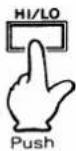
1) Select output power.
2) Push [PTT] SWITCH on microphone.
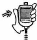
3) Speak into microphone.
4) Release [PTT] SWITCH.
5 - 4 AFC FUNCTION
1) Push TUNING CONTROL.

2) Push TUNING CONTROL again.
Before transmitting, be sure your transmit frequency is not being used by other stations.
1) Push the [HI/LO] SWITCH to select HIGH or LOW output power alternately.
- When LOW power is selected, the "LOW" appears on the LCD READOUT.
HIGH : 10W LOW : 1W
NOTE: When using HIGH, the IC-1200A/E may become warm. This is normal.
2) Push the [PTT] SWITCH on the microphone to transmit.
- The red [T/R] INDICATOR lights and the "S/RF" INDICATOR on the LCD READOUT shows the relative output power of the transmitter.
3) Speak into the microphone using your normal voice level.
- Do not hold the microphone too closely to your mouth or speak too loudly. This may distort the signal.
4) Release the [PTT] SWITCH to return to receiving.
• The red [T/R] INDICATOR goes out.
The AFC function automatically tunes receive/transmit frequencies in the IC-1200A/E. The green center meter lights up as soon as a signal is fine tuned. The AFC operates in a range of ±7kHz .
If the internal VXO/RIT SWITCH is in the RIT position, only receive frequencies can be automatically tuned.
1) Push the TUNING CONTROL to activate the AFC function.
- The AFC INDICATOR lights and the decimal point disappears from the LCD READOUT.
NOTE: The TUNING CONTROL does not operate when signals are received during AFC operation. However, when no signals are received the TUNING CONTROL operates within ±7kHz in the IC-1200A/E (LCD READOUT does not change).
2) Push the TUNING CONTROL again to cancel the AFC function.
- The AFC function is also cancelled if the scan function is activated.
6 - 1 MEMORY OPERATIONS
(1) MEMORY READING
Memory channels 1 \~ 21 are useful for storing often-used frequencies. Channel 21 is reserved for the call channel. Refer to p. 18 for more information.
1) Select MEMORY mode.
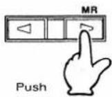
2) Select a memory channel.
1) Push the [MR] side of the [VFO/MR] SWITCH to select the MEMORY mode.
- The letter "M" appears below the small memory channel number on the right side of the LCD READOUT to indicate the MEMORY mode is selected.
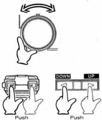
2) Turn the TUNING CONTROL to select the desired memory channel.
- The memory channel can be changed also by the [DOWN/UP] SWITCH or microphone [UP]/[DN] SWITCH.
- If you want to change the frequency (not channel number), push and hold the [WRITE] SWITCH to transfer the memorized frequency to the VFO mode. Refer to p. 14 (3) MEMORY CHANNEL TO VFO TRANSFERS.
(2) MEMORY PROGRAMMING
Use the following procedure to store operating frequencies plus duplex and memory skip information in memory channels. The duplex and memory skip functions are described in later sections.
1) Select a memory channel.
2) Select VFO mode.
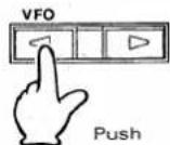
3) Select information you wish to write into a memory channel.
1) Select the desired memory channel to be programmed.
2) Push the [VFO] side of the [VFO/MR] SWITCH to select VFO mode.
3) While in VFO mode, select the information you wish to write into a memory channel:
a) Operating frequency (p. 11)
b) Duplex and subaudible tone (p. 16)
c) Memory skip (p. 15)
4) Push [WRITE] SWITCH.

4) Push and hold the [WRITE] SWITCH for approximately 0.5 seconds, to write the information into a memory channel.
- The 3 short beep tones indicate the information selected in step 3) is now stored in the memory channel.
- Push the [MR] side of the [VFO/MR] SWITCH to confirm the memory channel has the correct information stored.
(3) MEMORY CHANNEL TO VFO TRANSFERS
1) Select memory channel to be transferred.
2) Push and hold [WRITE] SWITCH to transfer.

At times it may be desirable to transfer the contents of a memory channel to the VFO. Perform the following steps:
1) Select the memory channel containing the information to be transferred.
- Refer to MEMORY READING for information on selecting memory channels.
2) Push and hold the [WRITE] SWITCH for approximately 0.5 seconds.
- The 3 short beep tones indicate that the information contained in the memory channel has been transferred to the VFO.
- After the transfer is completed, the IC-1200A/E changes to VFO mode and MEMORY MODE INDICATOR "M" disappears from the LCD READOUT.
- This transfer function does not affect the contents of the memory channel.
6 - 2 SCAN OPERATIONS
The IC-1200A/E is equipped with two different scans, FREQUENCY SCAN and MEMORY SCAN.
(1) FREQUENCY SCAN
FREQUENCY SCAN searches 1240 \~ 1300MHz frequencies in programmed tuning step increments. See p. 11 for step increments information.
1) Adjust [SQL/CHK] CONTROL.
2) Select VFO mode.
3) Start scan.
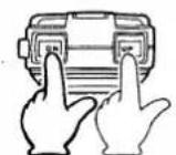
Push and hold
1) Turn the [SQL/CHK] CONTROL clockwise until the received noise is quieted.
2) Push the [VFO] side of the [VFO/MR] SWITCH to select VFO mode.
3) Push and hold the [UP] or [DN] SWITCH on the microphone for approximately 0.5 seconds.
- Push [UP] : Scans upwards. Push [DN] : Scans downwards.
- The scan starts and the decimal point on the LCD READOUT blinks.
- The scan stops when a signal is received and starts again automatically after 15 seconds, or 3 seconds after it disappear.
4) Scan stop.
4) Push the microphone [UP] or [DN] SWITCH again to stop the scan.
- Transmitting or rotating the TUNING CONTROL also cancels the scan.
(2) MEMORY SCAN
1) Adjust [SQL]/[CHK] CONTROL.
2) Select MEMORY mode.
3) Start scan.
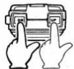
Push and hold
4) Stop scan.
(3) MEMORY SKIP FUNCTION
1) Select MEMORY mode.
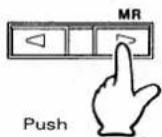
2) Select a memory channel.
3) Push [SET] SWITCH.
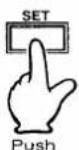
4) Cancel memory skip channel.
MEMORY SCAN searches all 21 memory channels except memory skip channels.
1) Turn the [SQL/CHK] CONTROL clockwise until the receive noise is quieted.
2) Push the [MR] side of the [VFO/MR] SWITCH to select MEMORY mode.
3) Push and hold the [UP] or [DN] SWITCH on the microphone for approximately 0.5 seconds.
- Push [UP] : Scans upwards Push [DN] : Scans downwards
- The scan starts and the decimal point on the LCD READOUT blinks.
- The scan stops when a signal is received and starts again automatically after 15 seconds, or 3 seconds after it disappears.
4) Push the microphone [UP] or [DN] SWITCH again to stop the scan.
- Transmitting or rotating the TUNING CONTROL also cancels the scan.
Memory channels which are not required to be scanned may be eliminated from the memory channel scan by the following procedure:
1) Push the [MR] side of the [VFO/MR] SWITCH to select MEMORY mode.
2) Rotate the TUNING CONTROL to select a required memory channel to skip.
3) Push the [SET] SWITCH.
- The "SKIP" INDICATOR appears on the LCD READOUT.
- The selected channel will now be skipped when using MEMORY SCAN.
4) Push the [SET] SWITCH again to cancel the memory skip function on this channel.
NOTE: The memory channel scan will not operate if all memory channels are programmed to be skipped.
6 - 3 DUPLEX OPERATIONS
Duplex mode allows operation with a transmit frequency that is different than the receive frequency. This is necessary when operating through repeaters.
(1) DUPLEX PROGRAMMING
NOTE: The offset value is the frequency difference between the receive and transmit frequencies when using Duplex mode.
1) Select VFO mode.
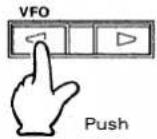
2) Select a receive frequency.
3) Push [SET] SWITCH repeatedly until "OW" flashes.
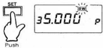
4) Program offset frequency.
5) Select VFO mode.
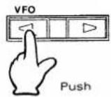
6) Select Duplex mode.

7) Push [SQL/CHK] CONTROL to check transmit frequency.

1) Push the [VFO] side of the [VFO/MR] SWITCH to select VFO mode.
2) Turn the TUNING CONTROL to select a receive frequency.
3) Push the [SET] SWITCH repeatedly until the "OW" INDICATOR begins flashing. The offset frequency and the offset programming symbol "F" or "P" appear on the LCD READOUT.
- The fixed offset "F" or programmed offset "P" are selected by pushing the [DOWN/UP] SWITCH.
- The fixed offset is 12MHz (IC-1200A) or 35MHz (IC-1200E).
4) If necessary, the offset frequency can be programmed by turning the TUNING CONTROL while "P" appears.
5) Push the [VFO] side of the [VFO/MR] SWITCH to select VFO mode.
6) Push the [DUP] SWITCH repeatedly to select Duplex or Simplex mode. In Duplex mode "DUP—" or "DUP+" and "TONE" appear on the LCD READOUT.
- "DUP—" : The transmit frequency is lower than the receive frequency by the offset value.
- "DUP+" : The transmit frequency is higher than the receive frequency by the offset value.
7) Push the [SQL/CHK] CONTROL to monitor the transmit frequency when Duplex mode is selected.
- This allows checking of the signal strength of your contacted station directly without going through a repeater. If the signal is received strongly enough directly, both stations should move to a simplex frequency.
(2) SUBAUDIBLE TONE ENCODER (IC-1200A only)
The built-in tone encoder allows access to repeaters which require a subaudible tone superimposed on the transmit signal.
●PROGRAMMING THE SUBAUDIBLE TONE ENCODER
1) Select VFO mode.
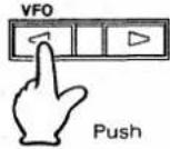
1) Push the [VFO] side of the [VFO/MR] SWITCH to select VFO mode.
2) Push [SET] SWITCH.
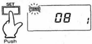
2) Push the [SET] SWITCH repeatedly until the "TONE" INDICATOR flashes on the LCD READOUT.
3) Select one of tone memories.
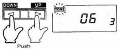
3) Push the front panel [DOWN/UP] SWITCH to select one of the tone memories.
- The tone number memories are numbered "1", "2" and "3" and are designated with small numbers on the right side of the LCD READOUT.
4) Select a tone number.
4) Turn the TUNING CONTROL to select a subaudible tone number.
- Refer to the SUBAUDIBLE TONE ENCODER FREQUENCY CHART on p. 18 to determine the tone number.
5) Select VFO mode.
5) Push the [VFO] side of the [VFO/MR] SWITCH to select the VFO mode.
6) Transmit subaudible tone.
6) A subaudible tone is transmitted automatically by pushing the [PTT] SWITCH during Duplex operation.
NOTE: If a subaudible tone is not necessary, select tone number "00"
- SUBAUDIBLE TONE ENCODER FREQUENCY CHART
(When using the IC-1200A with repeaters)
| TONE NUMBER | FREQUENCY (Hz) | TONE NUMBER | FREQUENCY (Hz) | TONE NUMBER | FREQUENCY (Hz) |
| 00 | NO TONE | 14 | 107.2 | 28 | 173.8 |
| 01 | 67.0 | 15 | 110.9 | 29 | 179.9 |
| 02 | 71.9 | 16 | 114.8 | 30 | 186.2 |
| 03 | 74.4 | 17 | 118.8 | 31 | 192.8 |
| 04 | 77.0 | 18 | 123.0 | 32 | 203.5 |
| 05 | 79.7 | 19 | 127.3 | 33 | 210.7 |
| 06 | 82.5 | 20 | 131.8 | 34 | 218.1 |
| 07 | 85.4 | 21 | 136.5 | 35 | 225.7 |
| 08 | 88.5 | 22 | 141.3 | 36 | 233.6 |
| 09 | 91.5 | 23 | 146.2 | 37 | 241.8 |
| 10 | 94.8 | 24 | 151.4 | 38 | 250.3 |
| 11 | 97.4 | 25 | 156.7 | ---- | ---- |
| 12 | 100.0 | 26 | 162.2 | ---- | ---- |
| 13 | 103.5 | 27 | 167.9 | ---- | ---- |
(3) 1750Hz TONE CALL (IC-1200E only)
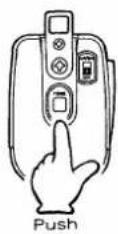
Push and hold the [TONE] SWITCH on the back of the microphone for approximately 1 \~ 3 seconds to open the repeater.
6-4 CALL CHANNEL OPERATIONS
1) Push [CALL] SWITCH.
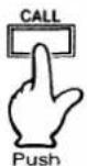
2) Push [CALL] SWITCH again.
Your highest priority channel can be easily called if it is programmed in memory channel 21. This function may be helpful for quick monitoring.
1) Push the [CALL] SWITCH to select a frequency stored in memory channel 21.
- The call channel symbol "C" appears on the LCD READOUT.
2) Push the [CALL] SWITCH again to cancel the call channel function.
- The IC-1200A/E returns to the function in use before the call channel function was selected.
• "C" disappears from the LCD READOUT.
- The [VFO/MR] SWITCH may also be used to return directly to either VFO or MEMORY mode.
7 - 1 MICROPHONE
The supplied HM-12 or HM-15 MICROPHONE has the following operating functions:
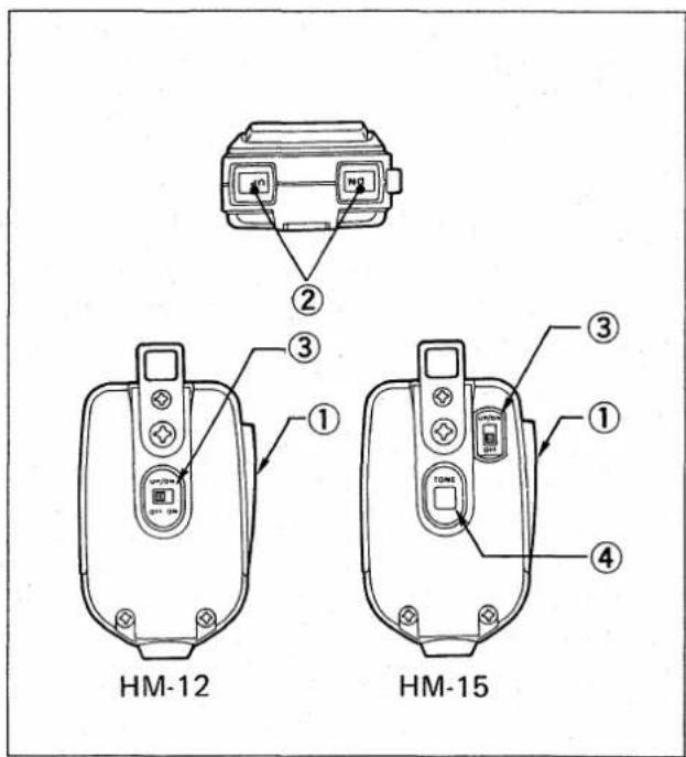
① [PTT] SWITCH:
Push this switch to begin transmitting.
② [UP]/[DN] SWITCHES:
Push either of these switches to increase or decrease frequencies or memory channel number depending on the mode.
Push and hold either of these switches to start the scan function. Refer to SECTION 6-1 SCAN FUNCTION.
③ UP/DOWN ON-OFF SWITCH:
When this switch is OFF, the [UP]/[DN] SWITCHES do not operate. This feature eliminates accidental or unwanted scanning.
④ [TONE] SWITCH (HM-15 only):
Push this switch to transmit a 1750Hz tone.
7 - 2 BACKUP BATTERY
The IC-1200A/E contains a lithium battery as a backup for the internal microcomputer memory in the transceiver. It is a reliable backup device, proven to last for more than five years, which protects the IC-1200A/E from external power source removal or interruptions.
After using the IC-1200A/E for five years change the battery if there are repeated cases of display malfunction.
- If the internal backup battery is exhausted, the IC-1200A/E will still operate normally. However, frequencies cannot be memorized.
7 - 3 RESETTING THE INTERNAL CPU
The LCD READOUT may occasionally display erroneous information either during operation or when first applying power. This may be due to an external cause such as static electricity.
When this sort of problem occurs, turn power OFF, wait a few seconds and turn power ON again. If the problem persists, reset the internal CPU according to the following procedures:
CAUTION: After resetting the CPU, all information (memory channels and other settings) must be re-programmed.
- CPU resetting
Hold down the TUNING CONTROL and turn power ON. The CPU is now reset.
7 - 4 OPTIONAL UNITS
The following are descriptions for the operation of two optional units which provide alternative squelch circuits. Refer to the INSTRUCTION sheets which accompany each unit for additional information. See p. 24 for installation information.
(1) PROGRAMMING THE UT-28 DIGITAL CODE SQUELCH UNIT
The group code is a five digit number which must be programmed identically in both the transmitting and receiving transceivers in order for the digital code squelch system to function. Any number from 00000 to 99999 inclusive may be programmed.
1) Push [T/D.SQL] SWITCH.
1) Push the [T/D.SQL] SWITCH.
- "D.SQL" appears on the LCD READOUT.
2) Push [SET] SWITCH.

2) Push the [SET] SWITCH.
- "D.SQL" begins flashing on the LCD READOUT.
- A five digit group code and the memory in which it is stored appear. There are three memories reserved for storing group codes.
3) Select group code memory.

3) Use the front panel [DOWN/UP] SWITCH to select the desired group code memory.
4) Push [SET] SWITCH again.
4) Push the [SET] SWITCH again.
- "AQS" begins flashing on the LCD READOUT and "D.SQL" disappears.
- A single digit in the group code also begins flashing.
AQS refers to Amateur Quinmatic System which includes digital code squelch as one feature.
5) Set desired number.
5) Turn the TUNING CONTROL to set the flashing digit to the number desired.
6) Select another group code.
6) Use the [DOWN/UP] SWITCH on the FRONT PANEL to select another digit in the group code.
- The newly selected digit begins flashing and the digit may be set with the TUNING CONTROL.
7) Set remaining group code digits.
7) Set the three remaining group code digits in the same way.
8) Push [SET] SWITCH.
8) Push the [SET] SWITCH to return to operating mode.
(2) PROGRAMMING THE UT-29 TONE SQUELCH UNIT
1) Select Simplex mode.
1) Select Simplex mode by using the [DUP] SWITCH.
2) Push [T/D.SQL] SWITCH.
2) Push the [T/D.SQL] SWITCH.
- "D.SQL" and "TONE" appear on the LCD READOUT.
3) Push [SET] SWITCH.
3) Push the [SET] SWITCH.

- "D.SQL" and "TONE" begin flashing on the LCD READOUT. A tone number and the tone memory channel also appear on the LCD READOUT.
4) Select tone memory channel.
4) Push the [DOWN/UP] SWITCH repeatedly to select the desired tone memory channel.
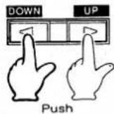
- There are three tone memory channels.
5) Choose tone number.
5) Turn the TUNING CONTROL to choose the required tone number.
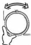
- Refer to the chart below for the correlation between the tone numbers and their associated frequencies.
6) Push [SET] SWITCH.
6) Push the [SET] SWITCH again to return to operating mode.
-UT-29 TONE ENCODER/ DECODER FREQUENCY CHART
| TONE NUMBER | FREQ. (Hz) | TONE NUMBER | FREQ. (Hz) | TONE NUMBER | FREQ. (Hz) |
| 01 | 67.0 | 15 | 131.8 | 29 | 218.1 |
| 02 | 71.9 | 16 | 136.5 | 30 | 225.7 |
| 03 | 77.0 | 17 | 141.3 | 31 | 233.6 |
| 04 | 82.5 | 18 | 146.2 | 32 | 241.8 |
| 05 | 88.5 | 19 | 151.4 | 33 | 250.3 |
| 06 | 94.8 | 20 | 156.7 | 34 | 67.0 |
| 07 | 100.0 | 21 | 162.2 | 35 | 71.9 |
| 08 | 103.5 | 22 | 167.9 | 36 | 74.4 |
| 09 | 107.2 | 23 | 173.8 | 37 | 77.0 |
| 10 | 110.9 | 24 | 179.9 | 38 | 79.7 |
| 11 | 114.8 | 25 | 186.2 | 39 | 82.5 |
| 12 | 118.8 | 26 | 192.8 | 40 | 85.4 |
| 13 | 123.0 | 27 | 203.5 | 41 | 88.5 |
| 14 | 127.3 | 28 | 210.7 | 42 | 91.5 |
(3) OPTIONAL SQUELCH UNIT OPERATION
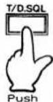
1) Push [T/D. SQL] SWITCH.
2) When a group code is received. (UT-28)
3) When a subaudible tone is received. (UT-29)
4) When an incorrect code or tone is received.
5) Cancel squelch unit operations.

Complete the above programming before attempting to use either optional squelch unit.
1) Push the [T/D.SQL] SWITCH to activate the squelch unit.
UT-28 : "D.SQL" appears on the LCD READOUT.
UT-29 : "D.SQL" and "TONE" appear on the LCD READOUT. (Simplex mode must be used.)
2) When a signal with the same group code as pre-programmed is received, "D.SQL" flashes on the LCD READOUT, the squelch opens, and audio is emitted from the speaker.
- The group code is automatically sent out and "D.SQL" flashes.
- The scan function cannot be used when the UT-28 is activated.
3) When a signal with the same subaudible frequency as pre-programmed is received, the squelch opens and audio is emitted from the speaker.
- The subaudible tone is automatically sent out when the IC-1200A/E is transmitting.
4) When an incorrect code or tone is received, the green [T/R] INDICATOR lights up and the "S/RF" INDICATOR appears. However, audio will not be emitted from the speaker.
NOTE: DO NOT transmit while the green [T/R] INDICATOR lights up as your transmission may interfere with other radio communications.
5) Push the [T/D.SQL] SWITCH to cancel squelch unit operation.
See UT-28 or UT-29 INSTRUCTIONS for further information.
(4) UNIT INSTALLATION

natural_image
Line drawing of a portable electronic device with labeled ports and control buttons, marked as Fig. 1 (no text or symbols on the device itself)CAUTION: Unplug the power cable before performing any work on the transceiver.
1) Unscrew the four cover screws on the top and bottom covers and remove the top and bottom covers. See Fig. 1.
natural_image
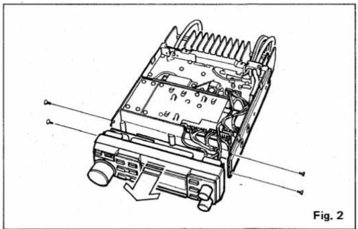
Technical line drawing of an electronic device with internal components and wiring, labeled as Fig. 2 (no text or symbols on the diagram itself)2) Unscrew the four screws on the left and right sides of the front panel. Remove the front panel. Be sure not to cut or damage any wires during removal. See Fig. 2.
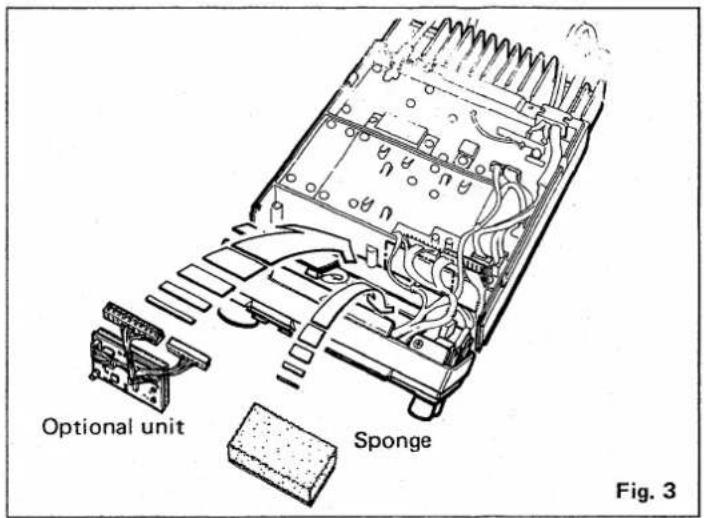
3) Adhesive tape is applied to the sponge on the back of the optional UT-28 or UT-29 unit. Peel the protective paper from the sponge and attach the unit in the position shown in Fig. 3.
4) Peel the protective paper from the sponge that comes with IC-1200A/E, and attach the sponge to the IC-1200A/E in the position shown in Fig. 3.
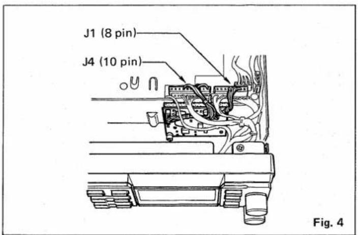
5) Connect the 10-pin and 8-pin plugs on the optional unit into J4 and J1 on the IC-1200A/E PLL UNIT, respectively. See Fig. 4.
6) Re-attach the front panel and the top and bottom covers of the transceiver.
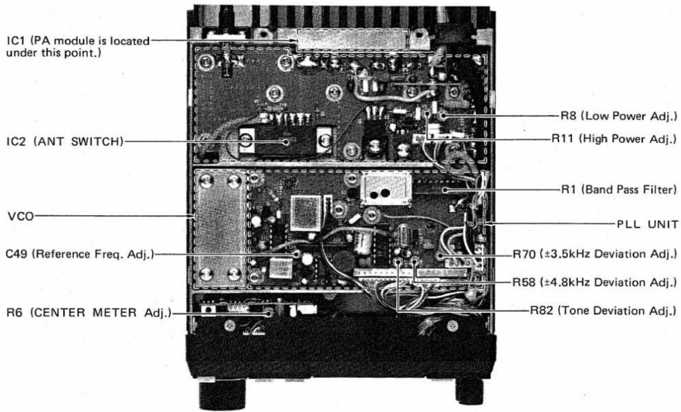
■ TOP VIEW (PLL/PA UNIT)
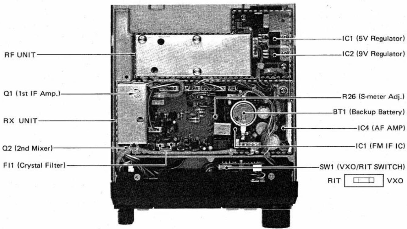
■ BOTTOM VIEW (RX/RF UNIT)
SECTION 9 MAINTENANCE
(1) OPERATING ENVIRONMENT

AVOID using the IC-1200A/E in excessively hot, humid or dusty environments and DO NOT subject the transceiver to strong vibrations or install it where water damage could result.
(2) ADJUSTMENTS

No internal adjustment of the transceiver is required since all variable components have been set correctly by the factory. Misadjusting certain components may damage the transceiver.
(3) MALFUNCTIONS

A variety of apparent problems can be solved by simply resetting the internal microcomputer in the IC-1200A/E. Refer to p. 19 RESET-TING THE INTERNAL CPU.
(4) CLEANING
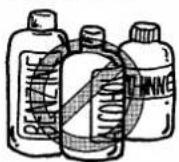
The IC-1200A/E will eventually require cleaning after sitting in your ham shack for a period of time. Remove the three knobs from the front panel and use a soft cloth with a mild, soapy solution. DO NOT use strong chemicals or cleaning solvents. Wipe dry before replacing the knobs on the panel.
(5) FUSES
Locate the cause for a blown fuse before replacing it and attempting to operate the IC-1200A/E again. The IC-1200A/E uses 10 A fuses in the power cable.
- CHANGING A FUSE
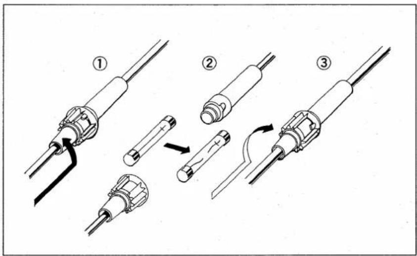
The following chart is designed to help you correct problems which are not equipment malfunctions. If you are not able to locate the cause of the problem or to solve it through the use of this chart, contact your nearest ICOM Service Center or Dealer.
| PROBLEM | POSSIBLE CAUSE | SOLUTION |
| 1. Power does not come on when the [VOL/PWR] CONTROL is pushed ON. | Power connector is making poor contact.Polarity of the power connection is wrong.Blown fuse. | Check the connector pins.Disconnect the power cable, replace the blown fuse, then reconnect the power cable observing proper polarity.Check for the cause, then replace the fuse. |
| 2. No sound comes from the speaker. | Volume setting is too low.[SQL/CHK] CONTROL is set incorrectly.External speaker is connected. | Set volume to an appropriate level.Adjust squelch so the noise from the speaker is just quieted while receiving no signal.Check that the external speaker plug is inserted properly, and that the external speaker cable is not cut. |
| 3. Sensitivity is low and only strong signals are audible. | Antenna feedline is cut or short circuited. | Check, and if necessary, replace the feedline. |
| 4. No or low RF output power. | The LOW position is selected with the [HI/LO] SWITCH.[PTT] SWITCH on the microphone is not operating due to poor connection of the MIC CONNECTOR. | Push the [HI/LO] SWITCH to select the HIGH output power position.Check the connector pins on the MIC CONNECTOR. |
| 5. No modulation of the transmitter. | Poor connection of the MIC CONNECTOR. | Check the connector pins on the MIC CONNECTOR. |
| 6. Frequency does not change when the TUNING CONTROL is turned. | MEMORY mode is selected.AFC function is activated.Call channel is selected. | Push the [VFO] side of the [VFO/MR] SWITCH.Push the TUNING CONTROL. Refer to p. 12.Push the [CALL] SWITCH. Refer to p. 18. |
| 7. Repeater can not be accessed. | Wrong subaudible tone is programmed.Wrong offset frequency is programmed. | Set the correct subaudible tone. Refer to SECTION 5 - 6 (2).Set the correct offset frequency. Refer to SECTION 5 - 6 (1). |
| 8. An abnormal, out-of-band frequency is displayed on the LCD READOUT. | CPU malfunction.Lithium backup battery is exhausted. | Reset the CPU. Refer to p. 19.Take your IC-1200A/E to an authorized ICOM Dealer or Service Center. |
| 9. Scan function does not stop ever. when signals are received. | [SQL/CHK] CONTROL is set incorrectly. | Adjust squelch so the noise from the speaker is just quieted while receiving no signal. |
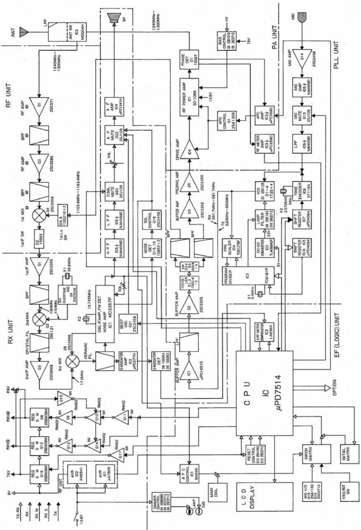
flowchart
graph TD
    subgraph CPU
        A["CPU μPD7514"]
        B["RF UNIT"]
        C["PLL UNIT"]
    end

    subgraph RX UNIT
        D["RF UNIT"]
        E["ANT"]
    end

    subgraph CPU_PH
        F["MINER CONTROL Q4 25600M Q9 252712 Q8 252712"]
        G["LAMP Cus"]
        H["MAIN DIAL"]
        I["LCD DISPLAY"]
        J["MIC U/D Q18 25SA1162 Q16 2502712"]
        K["VXO/RIT SW"]
        L["SWICH MATRIX"]
        M["INITIAL MATRIX"]
    end

    subgraph RX UNIT
        N["RF UNIT"]
        O["ANT"]
    end

    subgraph CPU_PH
        P["RF UNIT"]
        Q["ANT"]
    end

    style CPU fill:#f9f,stroke:#333
    style RX UNIT fill:#ccf,stroke:#333
    style CPU_PH fill:#cfc,stroke:#333
AC POWER SUPPLY(13.8V DC, 8A MAX.)PS-45 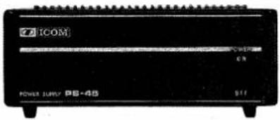 The OPC-102 interface cable to connect the PS-45 to the IC-1200A/E must be purchased separately. The OPC-102 interface cable to connect the PS-45 to the IC-1200A/E must be purchased separately. | FLEXIBLE MOBILE SWITCHBOXMICROPHONE FOR HS-15HS-15HS-15SB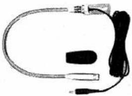 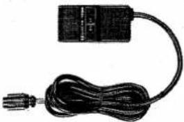 |
COMPRESSOR/GRAPHICEQUALIZER MICROPHSM-10 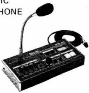 | DESK MICROPHONE SM-8 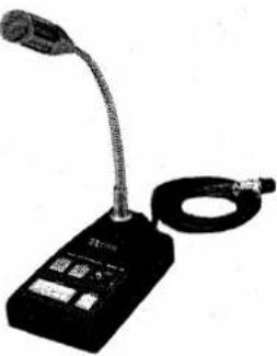 |
DTMF MICROPHONEIC-HM14SPEAKER-MICROPHONEFOR IC-1200A 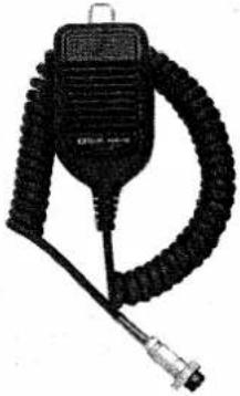 IC-HM16 SPEAKER-MICROPHONEFOR IC-1200EIC-HM17 IC-HM16 SPEAKER-MICROPHONEFOR IC-1200EIC-HM17 | BASE SPEAKERSP-7 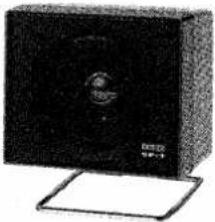 |
MOBILE SPEAKERSP-8 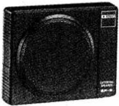 | MOBILE SPEAKERSP-10 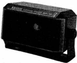 |
DIGITAL CODE SQUELCH UNITUT-28 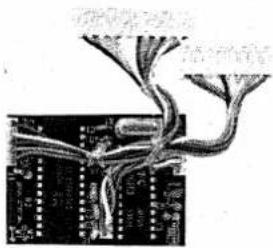 | TONE SQUELCH UNITUT-29 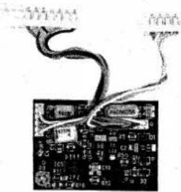 |

ICOM
- IC-1200A/E
- 1200MHz FM TRANSCEIVER
- TABLE OF CONTENTS
- SECTION 2 FEATURES
- ■ FRONT PANEL
- ■ REAR PANEL
- SECTION 4 INSTALLATIONS
- - ANTENNA
- • POWER SUPPLY
- • COAXIAL CABLE
- - 1 RECEIVING
- - 2 FREQUENCY SELECTING
- - 3 TRANSMITTING
- - 4 AFC FUNCTION
- - 1 MEMORY OPERATIONS
- MEMORY READING
- MEMORY PROGRAMMING
- MEMORY CHANNEL TO VFO TRANSFERS
- - 2 SCAN OPERATIONS
- FREQUENCY SCAN
- MEMORY SCAN
- MEMORY SKIP FUNCTION
- - 3 DUPLEX OPERATIONS
- DUPLEX PROGRAMMING
- SUBAUDIBLE TONE ENCODER (IC-1200A only)
- ●PROGRAMMING THE SUBAUDIBLE TONE ENCODER
- - SUBAUDIBLE TONE ENCODER FREQUENCY CHART
- 6-4 CALL CHANNEL OPERATIONS
- - 1 MICROPHONE
- - 2 BACKUP BATTERY
- - 3 RESETTING THE INTERNAL CPU
- - 4 OPTIONAL UNITS
- PROGRAMMING THE UT-28 DIGITAL CODE SQUELCH UNIT
- PROGRAMMING THE UT-29 TONE SQUELCH UNIT
- -UT-29 TONE ENCODER/ DECODER FREQUENCY CHART
- OPTIONAL SQUELCH UNIT OPERATION
- ■ TOP VIEW (PLL/PA UNIT)
- ■ BOTTOM VIEW (RX/RF UNIT)
- SECTION 9 MAINTENANCE
Marke : ICOM
Modell : IC-1200A
Kategorie : Empfänger