
IC-2410A - Empfänger ICOM - Kostenlose Bedienungsanleitung
Finden Sie kostenlos die Bedienungsanleitung des Geräts IC-2410A ICOM als PDF.


Benutzerfragen zu IC-2410A ICOM
0 Frage zu diesem Gerät. Beantworten Sie die, die Sie kennen, oder stellen Sie Ihre eigene.
Eine neue Frage zu diesem Gerät stellen
Laden Sie die Anleitung für Ihr Empfänger kostenlos im PDF-Format! Finden Sie Ihr Handbuch IC-2410A - ICOM und nehmen Sie Ihr elektronisches Gerät wieder in die Hand. Auf dieser Seite sind alle Dokumente veröffentlicht, die für die Verwendung Ihres Geräts notwendig sind. IC-2410A von der Marke ICOM.
BEDIENUNGSANLEITUNG IC-2410A ICOM
text_image
ICOM INSTRUCTION MANUALDUAL BAND FM TRANSCEIVER
IC-2410A IC-2410E IC-2410H
text_image
ICOM VANOS R/CALL 146500 447000 POWER V30L USOL SAND DUP T/T3GL PGR/CS HI/LOW SET YVOL U VOLIcom Inc.
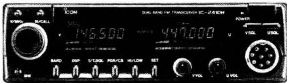
The photo shows the IC-2410H U.S.A. version.
IMPORTANT
READ THIS INSTRUCTION MANUAL CAREFULLY before attempting operation. If you have any questions regarding the operation of the IC-2410A/E/H, feel free to contact your nearest authorized Icom Dealer or Service Center.
SAVE THIS INSTRUCTION MANUAL — This instruction manual contains important safety and operating instructions for the IC-2410A/E/H.
FOREWORD
Thank you for choosing this lcom product.
The IC-2410A/E/H is a 144 and 430 (440) MHz dual band mobile transceiver. The IC-2410A/E/H is a compact, easy-to-operate and multi-function transceiver designed using Icom's state-of-the-art technology.
CAUTIONS
NEVER connect the transceiver to an AC outlet. This will ruin the transceiver.
NEVER connect the transceiver to a power source of more than 16 V DC. Check the power source before connecting the power cable.
NEVER place the transceiver where normal operation of the vehicle may be hindered or where it could cause bodily injury.
NEVER allow children to touch the transceiver.
DO NOT use or place the transceiver in areas with temperatures below -10^ (+14°F) or over +60^ (+140°F).
AVOID placing the transceiver in areas of direct sunlight, such as the dashboard.
BE CAREFUL! The heatsink may become hot when operating the transceiver continuously for long periods.
TABLE OF CONTENTS
IMPORTANT......i
FOREWORD ...... i
CAUTIONS i
TABLE OF CONTENTS ...... ii
UNPACKING....ii
1 PANEL DESCRIPTION.... 1\~6
2 INSTALLATION 7\~9
3 MODE CONSTRUCTION.... 10\~11
4 BASIC OPERATION 12\~20
5 MEMORY CHANNEL OPERATION 21\~22
6 CALL CHANNEL OPERATION 23
7 SCANNING OPERATION.... 24\~26
8 PRIORITY WATCH OPERATION 27\~28
9 UP SWITCH REMOTE 29
10 SELECTIVE CALLING (optional) 30\~35
11 OPTIONAL UNIT INSTALLATION 36
12 HM-56 ADVANCED FUNCTIONS (U.S.A. and Asia versions).... 37\~40
13 OPTIONAL DTMF REMOTE 41\~43
14 PARA-WATCH 44
15 MAINTENANCE 45\~46
16 SPECIFICATIONS 47
17 OPTIONS....48
UNPACKING
text_image
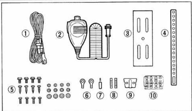
Diagram showing ten labeled parts of a mechanical or electrical component, including wires, pumps, and screws with numbered labels.Accessories included with the IC-2410A/E/H: Qty.
① DC power cable (OPC-044B) 1
② Microphone*....1
③ Mounting bracket....1
④ Mounting support bracket....1
⑤ Mounting screws, nuts and washers..... 1 set
⑥ Cable lugs....2
⑦ External speaker plug 1
⑧ Fuses (15 A)....2
⑨ Microphone hanger....1
⑩ Microphone sheet for HM-56....1
* U.S.A. and Asia versions : HM-56
Australia version : HM-58
Europe and Italy versions: HM-59
1 PANEL DESCRIPTION
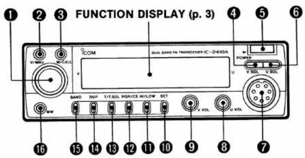
Front panel
text_image
FUNCTION DISPLAY (p. 3) V/MHz M/CALL COM DUAL SANS FAN TRANSCERIC IC-2/410A POWER U V SOL U SOL SAND DUF T/T.SOL PGR/CS HI/LOW SET V VOL U VOL 16 15 14 13 12 11 10 9 8 7① TUNING CONTROL
Selects the operating frequency (p. 12), the memory channel (p. 21), the contents of the SET mode display (p. 11) and the scanning direction (p. 25).
② VFO/MHz SWITCH [V/MHz]
Selects VFO mode.
Selects the 1 MHz tuning step in VFO mode.
Selects the 10 MHz tuning step when pushed and held.
③ MEMORY/CALL CHANNEL SWITCH [M/CALL]
Selects MEMORY mode or CALL CHANNEL mode.
Activates priority watch when pushed and held.
Cancels priority watch when the watch is activated.
④ VHF SQUELCH SWITCH [V SQL]
Selects the VHF band squelch threshold level. (p. 13)
Opens the VHF band squelch and monitors the VHF transmit frequency when pushed and held. (p. 17)
⑤ POWER SWITCH [POWER]
Turns the power ON and OFF.
⑥ UHF SQUELCH SWITCH [U SQL]
Selects the UHF band squelch threshold level. (p. 13)
Opens the UHF band squelch and monitors the UHF transmit frequency when pushed and held. (p. 17)
⑦ MICROPHONE CONNECTOR (p. 4)
Connects the supplied microphone or another suitable microphone.
PANEL DESCRIPTION
⑧ UHF VOLUME CONTROL [U VOL]
Adjusts the UHF band audio output level.
⑨ VHF VOLUME CONTROL [V VOL]
Adjusts the VHF band audio output level.
⑩ SET MODE SWITCH [SET]
Accesses SET mode and advances the SET mode display. (p. 11)
Activates the lock function when pushed and held. (p. 13)
⑪ TRANSMIT POWER SWITCH [HI/LOW] (p. 17)
Selects 1 of the 3 transmit output power levels.
Activates the RF attenuator function when pushed and held.
Reverses the SET mode display in SET mode.
⑫ PAGER/CODE SQUELCH SWITCH [PGR/CS]
(pgs. 33, 34)
Selects the function of an optional UT-55 DTMF ENCODER/DECODER UNIT.
- Activates the pager or code squelch function.
- Selects standby for optional Mic or External DTMF Remote when pushed and held.
⑬ TONE SWITCH [T/T.SQL]
Activates the subaudible tone encoder.* (p. 20)
Activates the optional pocket beep or tone squelch function when an optional UT-67 TONE SQUELCH UNIT is installed. (p. 35)
* U.S.A. version: Built-in
Other versions: Optional except for 88.5 Hz.
14 DUPLEX SWITCH [DUP] (p. 19)
Selects simplex, -duplex or +duplex.
15 BAND SWITCH [BAND]
Selects either VHF or UHF for the MAIN band.
Activates the SUB band access function when pushed and held.
16 MEMORY WRITE SWITCH [MW] (p. 21)
Programs a memory channel or a call channel.
Transfers the contents of a memory channel or a call channel to the VFO.
Announces the operating band frequency with a synthesized voice when an optional UT-66 VOICE SYNTHESIZER UNIT is installed. (p. 18)
1 PANEL DESCRIPTION
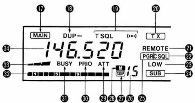
■ Function display
text_image
17 18 19 20 MAIN DUP- T SQL (101) TX 34 146.520 33 BUSY PRIO ATT M 15 REMOTE 21 PGRCSQL 22 LOW 23 SUB 32 1 5 9 SKIP 31 30 29 28 27 26 25The above diagram shows the VHF band display.
⑰ MAIN BAND INDICATOR
Appears above the frequency readout being used as the MAIN band.
18 DUPLEX INDICATOR (p. 19)
"DUP—" or "DUP" appears when semi-duplex is selected for repeater operation.
⑲ TONE INDICATORS (pgs. 20, 35)
"T" appears when the subaudible tone encoder is turned ON.
"T SQL" appears when the optional tone squelch function is activated.
"T SQL (●) " appears when the optional pocket beep function is activated.
⑳ TRANSMIT INDICATOR (p. 17)
Appears while transmitting.
21 REMOTE INDICATOR
Appears when optional Mic or External DTMF Remote is on standby.
Blinks when optional Mic or External DTMF Remote is activated.
22 CODE SQUELCH INDICATOR (p. 34)
Appears when the optional code squelch function is activated.
23 LOW POWER INDICATOR
Appears when low power 1 or 2 is selected on the MAIN band.
PANEL DESCRIPTION
24 SUB BAND ACCESS INDICATOR (p. 15)
Appears when the SUB band access function is activated.
Blinks when optional External DTMF Remote is activated.
25 PAGER INDICATOR (p. 33)
Appears when the optional pager function is activated.
26 MEMORY CHANNEL READOUT
Displays the memory channel number.
- Large "L" appears when the lock function is activated.
• Large "C" appears while in CALL CHANNEL mode.
- Small "c" appears when VFO mode is selected from CALL CHANNEL mode.
27 SKIP INDICATOR (p. 26)
Appears when the displayed memory channel is programmed as a skip channel.
28 MEMORY INDICATOR (p. 21)
Appears when MEMORY mode is selected.
29 RF ATTENUATOR INDICATOR (p. 14)
Appears when the RF attenuator circuit is activated.
30 PRIORITY WATCH INDICATOR (p. 27)
Appears when the priority watch function is activated.
31 BUSY INDICATOR
Appears when a signal is received or when the squelch is open.
32 S/RF INDICATOR
Displays the relative strength of a received signal.
Displays the selected level of transmit output power while transmitting.
33 SQUELCH LEVEL INDICATOR
Displays the squelch threshold level. (3 levels and open)
34 FREQUENCY READOUT
Displays the operating frequency (except during SET mode).
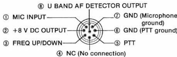
■ Microphone connector (front panel view)
text_image
⑧ U BAND AF DETECTOR OUTPUT ① MIC INPUT ② +8 V DC OUTPUT ③ FREQ UP/DOWN ④ NC (No connection) ⑤ PTT ⑥ GND (PTT ground) ⑦ GND (Microphone ground)1 PANEL DESCRIPTION
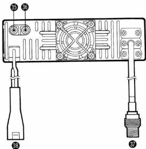
Rear panel
text_image
35 36 38 3735 430 (440) MHz SPEAKER JACK [430 (440) MHz SP]
36 144 MHz SPEAKER JACK [144 MHz SP]
Connect 4\~8 Ω speakers. Speakers operate as follows.
| Connected speaker | VHF audio | UHF audio |
| With no external speakers | Internal speaker(mixed audio) | |
| [144 MHz SP] only | External speaker | Internal speaker |
| [430 (440) MHz SP] only | External speaker(mixed audio) | |
| 2 speakers connected to the each jack | External via[144 MHz SP] | External via[430 (440)MHz SP] |
37 ANTENNA CONNECTOR (p. 9)
Accepts a 50 Ω dual band antenna with a PL-259 connector to the transceiver.
38 POWER RECEPTACLE [DC 13.8 V] (p. 8)
Accepts 13.8 V DC with the supplied DC power cable.
Microphone
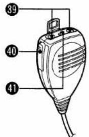
text_image
39 40 41Top and side panel
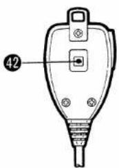
text_image
42HM-59 rear panel (Europe and Italy versions)
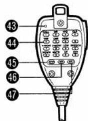
text_image
43 44 45 46 47HM-56 rear panel (U.S.A. and Asia versions)
39 FREQUENCY UP/DOWN SWITCHES [UP], [DN]
Push either switch to change the operating frequency or memory channel.
Push and hold either switch to start scanning.
Once a function has been programmed for Up Switch Remote, [UP] activates the function. (p. 29)
[UP] activates optional Mic DTMF Remote when in standby. (p. 41)
40 PTT SWITCH
Push and hold to transmit.
④1 LOCK SWITCH [LOCK]
Prevents accidental input from all keys except the PTT switch and [TONE] of the HM-59 hand microphone.
42 TONE CALL SWITCH (HM-59 only)
Push and hold to transmit a 1750 Hz tone call signal to access a repeater.
43 ACTIVE INDICATOR (HM-56 only)
Lights up or blinks when a key is pushed or a tone is being transmitted.
44 DTMF KEYBOARD (HM-56 only)
Used DTMF codes for auto patch, repeater control, optional Mic DTMF Remote and other functions. - Attach the supplied microphone sheet to the HM-56 keyboard.
45 MEMORY WRITE KEY [MW] (HM-56 only)
Used when writing a DTMF code into DTMF memory or re-dial code memory.
46 MEMORY READ KEY [MR] (HM-56 only)
Used when recalling and transmitting a DTMF code from DTMF code memory.
47 RE-DIAL KEY [RD] (HM-56 only)
Used when recalling and transmitting the last-transmitted DTMF code.
2 INSTALLATION
Location
Select a location which can support the weight of the transceiver and does not interfere with driving in any way. We recommend the locations shown in the diagram below.
NEVER place the transceiver where normal operation of the vehicle may be hindered or where it could cause bodily injury.
DO NOT place the transceiver where hot or cold air blows directly onto it.
AVOID placing the transceiver in direct sunlight.
• EXAMPLE INSTALLATION LOCATIONS
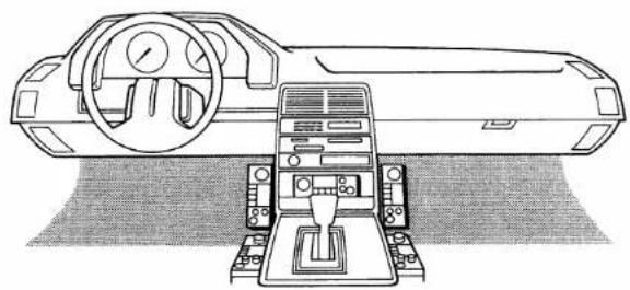
natural_image
Line drawing of a car interior with steering wheel and dashboard (no text or symbols)Mounting
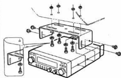
1) Drill 4 holes where the mounting bracket is to be installed.
2) Insert the supplied screws, nuts and washers through the mounting bracket and tighten.
3) The supplied mounting support bracket may be of help in achieving tight installation.
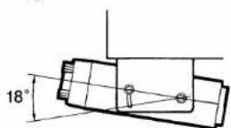
4) Adjust the angle for the clearest view of the function display.
• MOUNTING PROCEDURE
natural_image
Technical line drawing of a mechanical device with mounting holes and control panel (no text or symbols)When using
self-tapping screws.
- Hole sizes:
Approx. 5.5\~6 mm when using nuts.
Approx. 2\~3 mm when using self-tapping screws.
(1 mm ÷ 1/32 in)
Battery connection
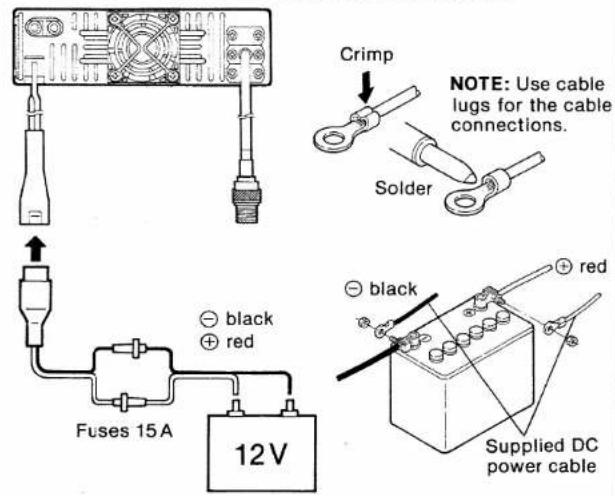
NEVER connect the transceiver directly to a 24 V battery.
DO NOT use the cigarette lighter socket for power connections.
To prevent voltage drops, solder or crimp the cable lug when connecting the power cable to the battery.
• CONNECTING TO A DC POWER SOURCE
text_image
Crimp NOTE: Use cable lugs for the cable connections. Solder black red Fuses 15A 12V black red Supplied DC power cable■ DC power supply connections
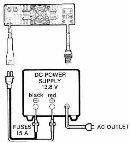
Use a 13.8 V DC power supply as below:
IC-2410A/E: More than 8 A capability.
IC-2410H : More than 11 A capability.
Make sure the ground terminal of the DC power supply is grounded.
• CONNECTING TO A DC POWER SUPPLY
text_image
DC POWER SUPPLY 13.8 V black red FUSES 15 A AC OUTLET2 INSTALLATION
Antenna connection
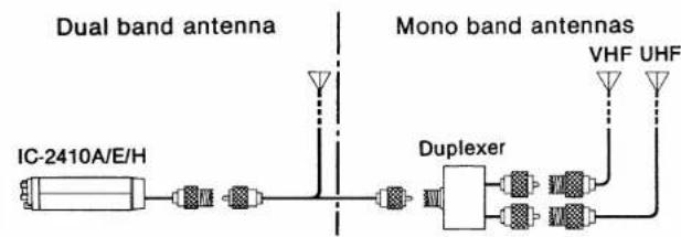
You can use a dual band antenna because a duplexer is installed in the IC-2410A/E/H. However, an external duplexer must be connected when using a separate antenna for each band.
To obtain maximum performance from the transceiver, select a high-quality antenna and a good location for it.
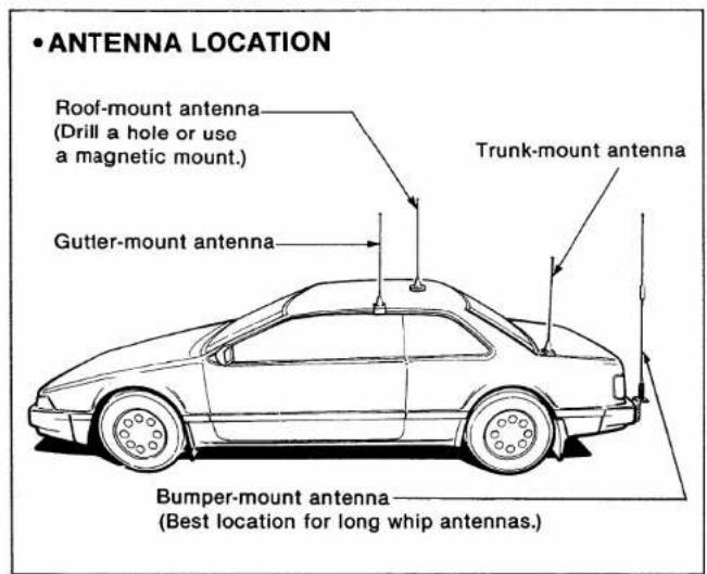
text_image
• ANTENNA LOCATION Roof-mount antenna (Drill a hole or use a magnetic mount.) Trunk-mount antenna Gutter-mount antenna Bumper-mount antenna (Best location for long whip antennas.)• ANTENNA CONNECTOR (PL-259)
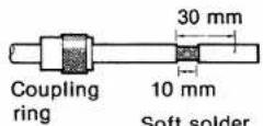
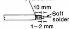
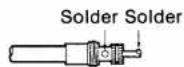
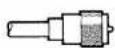
1) Slide the coupling ring over the coaxial cable.
2) Strip the cable as shown in the diagram, and soft solder the center conductor.
3) Slide the connector body onto the cable and solder.
4) Screw the coupling ring onto the connector body.
(10 mm÷3/8 in)
• ANTENNA CONNECTION
flowchart
graph LR
    A["IC-2410A/E/H"] --> B["Wireless"]
    B --> C["Duplexer"]
    C --> D["VHF"]
    C --> E["UHF"]
    F["Dual band antenna"] --> G["Antenna"]
    H["Mono band antennas"] --> I["Antenna"]
    J["Wireless"] --> K["Antenna"]
    L["Wireless"] --> M["Antenna"]
    N["Wireless"] --> O["Antenna"]
MODE CONSTRUCTION
■ Mode types
The IC-2410A/E/H has 4 different modes on each band, VHF and UHF, for multi-function operations.
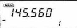
• VFO MODE
Used for normal operations.
- MEMORY MODE
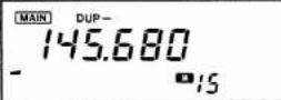
Used for operating the transceiver using memory channel contents. 15 memory channels are available in each band.
- CALL CHANNEL MODE
Used for programming your most-often-used channel.
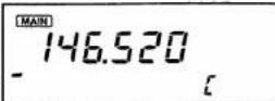
- SET MODE
Used for initializing the transceiver conditions as described on p. 11.
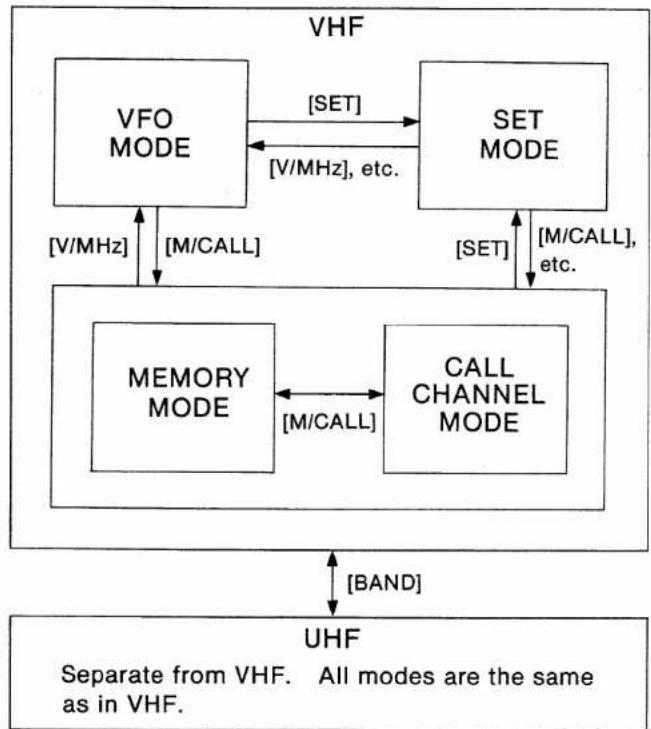
■ Mode construction chart
The 4 different modes are constructed as described in the following chart.
flowchart
graph TD
    A["VFO MODE"] -->|[SET] | B["SET MODE"]
    B -->|[V/MHz], etc.| A
    C["MEMORY MODE"] -->|[V/MHz]| A
    D["CALL CHANNEL MODE"] -->|[SET] | B
    E["UHF"] -->|[BAND]| C
    style A fill:#f9f,stroke:#333
    style B fill:#f9f,stroke:#333
    style C fill:#f9f,stroke:#333
    style D fill:#f9f,stroke:#333
    style E fill:#ccf,stroke:#333
3 MODE CONSTRUCTION
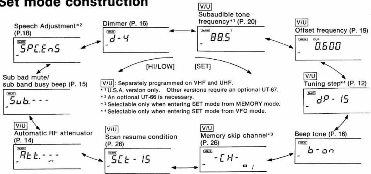
■ Set mode construction
flowchart
graph TD
    A["Speech Adjustment*2 (P.18)"] --> B["Dimmer (P. 16)"]
    B --> C["V/U Subaudible tone frequency*1 (P. 20)"]
    C --> D["Offset frequency (P. 19)"]
    D --> E["V/U Tuning step*4 (P. 12)"]
    E --> F["Beep tone (P. 16)"]
    F --> G["V/U Memory skip channel*3 (P. 26)"]
    G --> H["V/U Scan resume condition (P. 26)"]
    H --> I["Automatic RF attenuator (P. 14)"]
    I --> J["V/U Automatic RF attenuator (P. 15)"]
    J --> K["Sub bad mute/sub band busy beep (P. 15)"]
    K --> L["V/U Separately programmed on VHF and UHF. *1 U.S.A. version only. Other versions require an optional UT-67. *2 An optional UT-66 is necessary. *3 Selectable only when entering SET mode from MEMORY mode. *4 Selectable only when entering SET mode from VFO mode."]
- SELECTING SET MODE
1) Push [BAND] to select the desired band.
2) Select either VFO or MEMORY mode.
3) Push [SET] to enter SET mode.
NOTE:
- If no operation is performed for 30 sec. in SET mode, the transceiver returns to the previous mode automatically.
- When setting the tuning step, enter SET mode from VFO mode.
- When setting the memory skip channel, enter SET mode from MEMORY mode.
BASIC OPERATION
4
Frequency setting
The operating frequency can be set with the tuning control or [UP] and [DN] on the microphone.
1) Push [POWER] IN to turn power ON.
2) Push [BAND] to select VHF or UHF.
- When "L" appears on the function display, see p. 13 to cancel the lock function.
3) Push [V/MHz] to select VFO mode.
- If the kHz digits disappear, push [V/MHz] again.
4) Rotate the tuning control or push [UP] or [DN] on the microphone to change the frequency.
• The tuning step can be changed as described at right.
- Push [V/MHz] for a 1 MHz tuning step.
- When an optional DTMF Remote is activated, the frequency can be set using DTMF code. (pgs. 41\~43)
5) To set the other band frequency, push [BAND] and then repeat steps 3 and 4.
NOTE: When Up Switch Remote is activated, [UP] or [DN] cannot be used for frequency setting. See p. 29 for details.
USING SET MODE
• TUNING STEP SELECTION
VFO mode → SET mode V/U separate setting
text_image
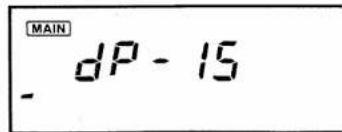
MAIN dP - 151) Push [BAND] to select VHF or UHF.
2) Push [V/MHz] to select VFO mode.
3) Push [SET] several times until "dP" appears on the function display as shown above.
• Refer to p. 11 for SET mode details.
4) Rotate the tuning control for the desired tuning step.
• 5, 10, 12.5, 15, 20 and 25 kHz steps are available.
5) Push any switch except [SET] and [HI/LOW] to set the value and to exit SET mode.
4 BASIC OPERATION
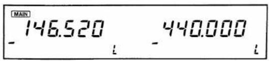
■ Lock function
The lock function locks the tuning control and all switches except [SET], [V SQL], [U SQL] and PTT to prevent the operating frequency and function from changing accidentally.
The optional voice synthesizer can be activated even when the lock function is turned ON. (p. 18)
text_image
MAIN -146.520 -440.000 i iPush and hold [SET] until "L" appears on the function display.
- To cancel the function, push and hold [SET] until "L" disappears.
■ Receiving
The transceiver allows you to receive both VHF and UHF bands simultaneously.

text_image
f bands simultaneously. ① ②, ④ ⑥ ⑦ ⑤ ③ ⑦1) Push [POWER] IN to turn power ON.
2) Push both [V SQL] and [U SQL] several times until the squelch indicators disappear.
- "BUSY" appears on each band display.
3) Rotate both [V VOL] and [U VOL] to adjust the audio levels.
4) Push both [V SQL] and [U SQL] several times until noise disappears.
5) Push [BAND] to select VHF or UHF as the MAIN band.
6) Push [V/MHz] to select VFO mode when another mode has been selected.
7) Set the operating frequency using the tuning control or [UP] and [DN] on the microphone.
• See p. 12 for more information.
- See p. 15 for accessing the SUB band and setting a frequency.
8) When receiving a signal on the set frequency:
- Squelch opens and the transceiver emits audio.
- "BUSY" appears.
• The S/RF indicator shows relative signal strength.
- SUB band mute or SUB band busy beep is useful for dual band receiving. (p. 15)
■ RF attenuator
The 20 dB RF attenuator does not allow receiving of weak signals. This attenuator, therefore is useful for short-distance contact since undesired long-distance signals will be eliminated.
Push and hold [HI/LOW] until "ATT" appears.
- To cancel the function, push and hold [HI/LOW] until "ATT" disappears.
- The function can be automatically turned ON with output power selection. See at right.
USING SET MODE
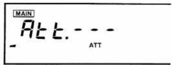
• AUTOMATIC RF ATTENUATOR V/U separate setting
The RF attenuator function can be automatically turned ON when the low power 1 is selected.
text_image
MAIN Att. - - - ATT1) Push [BAND] to select VHF or UHF.
2) Push [SET] several times until "Att" appears on the function display and the attenuator indicator blinks as shown above.
• Refer to p. 11 for SET mode details.
3) Rotate the tuning control to set the condition.
- "Att.- - -": Automatic RF attenuator OFF
"Att.Aut": Automatic RF attenuator ON
4) Push any switch except [SET] and [HI/LOW] to set the condition and to exit SET mode.

SUB band access
This function enables you to set the SUB band contents while transmitting or receiving on the MAIN band.
It is easy to access the SUB band and return to the MAIN band with the [BAND] switch.
Neither the optional pager nor code squelch function can be activated while accessing the SUB band. (p. 33)
1) Push and hold [BAND] to access the SUB band.
- "SUB" appears.
• The MAIN band still functions for receiving and transmitting.
2) Set a SUB band operating frequency or memory channel using the tuning control or [UP] and [DN] on the microphone.
- Set a function, if desired.
- The MAIN band output power cannot be changed while accessing the SUB band.
3) To exit the SUB band, push and hold [BAND] until "SUB" disappears.
• To switch from the SUB band to the MAIN band, push [BAND].
USING SET MODE
• SUB BAND MUTE/ SUB BAND BUSY BEEP
V/U same setting
The SUB band mute function automatically cuts out SUB band AF signals when both MAIN and SUB band signals are received.
The SUB band busy beep sounds when the SUB band squelch is closed to inform you that the SUB band squelch has been opened.
1) Push [SET] several times until "Sub" appears on the function display.
• Refer to p. 11 for SET mode details.
2) Rotate the tuning control to set the condition.
| DISPLAY | SUB BAND MUTE | BUSY BEEP |
| Sub.- - - | OFF | OFF |
| Sub.- - - (1•1) | OFF | ON |
| Sub. Aut | ON | OFF |
| Sub. Aut (1•1) | ON | ON |
3) Push any switch except [SET] and [HI/LOW] to set the condition and to exit SET mode.
■ Beep tone and dimmer
USING SET MODE
• BEEP TONE ON/OFF
V/U same setting
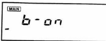
You can select silent operation with beep tone OFF or confirmation operation with beep tone ON.
To inform you which band is operating, high beep tone or low beep tone is emitted while controlling the VHF or UHF band, respectively.
text_image
MAIN b-on1) Push [SET] several times until "b-on" or "b-oFF" appears on the function display as shown above.
• Refer to p. 11 for SET mode details.
2) Rotate the tuning control to set the condition.
- "b-on": Beep tone ON
"b-oFF": Beep tone OFF
3) Push any switch except [SET] and [HI/LOW] to set the condition and to exit SET mode.
USING SET MODE
• DIMMER ADJUSTMENT
V/U same setting
Adjust the intensity according to lighting conditions and personal preference.
text_image
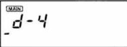
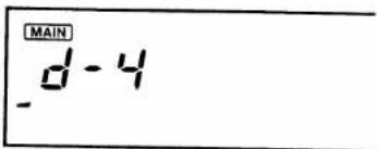
MAIN d-41) Push [SET] several times until one of "d-1"\~"d-4" appears on the function display as shown above.
• Refer to p. 11 for SET mode details.
2) Rotate the tuning control to set the desired intensity.
• The intensity level can be changed in 4 steps for d-1 (Dark)\~d-4 (Bright).
3) Push any switch except [SET] and [HI/LOW] to set the value and to exit SET mode.
4 BASIC OPERATION
■Transmitting
The transceiver can only transmit on the MAIN band.
CAUTION: Transmitting without an antenna may damage the transceiver.
NOTE 1: To prevent interference, listen on the frequency before transmitting while pushing and holding [V SQL] or [U SQL].
NOTE 2: To prevent howling, AVOID setting the UHF frequency near a multiple of the VHF frequency.
EXAMPLE: 145.000 MHz and 435.000 MHz
HM-56 only: Voice transmission is not possible while the active indicator on the HM-56 lights or blinks. (pgs. 37\~40)
1) Push [BAND] to select VHF or UHF.
2) Set the operating frequency. (p. 12)
3) If "DUP" or "DUP—" appears on the function display, push [DUP] until they disappear, thus indicating simplex.
• To operate through a repeater see p. 19.
4) Push [HI/LOW] to select the output power.
- "LPo-1" or "LPo-2" appears for 0.5 sec. when selecting low output power.
- "LOW" appears when selecting low output power.
• [HI/LOW] DOES NOT function while the SUB band access function is activated. (p. 15)
5) Push and hold the PTT switch to transmit.
• "TX" appears while transmitting.
• The S/RF indicator shows output power selection.
| POWER SELECTION | S/RF INDICATOR DURING TRANSMISSION | OUTPUT POWER | |
| IC-2410H | IC-2410A/E | ||
| High | 45 W* | 25 W | |
| Low 2 (LPo-2) | 10 W | 10 W | |
| Low 1 (LPo-1) | 5 W | 1 W | |
*430 (440) MHz band: 35 W
6) Speak into the microphone.
- DO NOT hold the microphone too close to your mouth or speak too loudly. This may distort the signal.
7) Release the PTT switch to receive.
■ Crossband full duplex operation
The transceiver receives SUB band audio during transmission on the MAIN band. Using this capability, full duplex operation is possible. No special setting is necessary for full duplex operation.
1) Set the desired transmit and receive frequencies on the MAIN and SUB bands respectively in your transceiver. (p. 12)
2) Set the same frequencies in reverse on the MAIN and SUB bands in the other transceiver.
3) Push and hold the PTT switch to activate full duplex.
• Transmitting and receiving activate simultaneously.
■ Optional voice synthesizer
The transceiver announces the operating frequency in English or Japanese when an optional UT-66 VOICE SYNTHESIZER UNIT is installed.
Push [MW] to announce the operating frequency.
- While accessing the SUB band, the transceiver announces the SUB band frequency.
USING SET MODE
• SPEECH ADJUSTMENT
(An optional UT-66 is necessary.)
V/U same setting
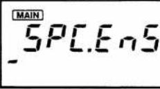
1) Push [SET] several times until "SPC" appears on the function display as shown above.
• Refer to p. 11 for SET mode details.
2) Rotate the tuning control to set the condition.
| DISPLAY | SPEECH CONDITION |
| SPC. EnS | Slower English |
| SPC. EnF | Faster English |
| SPC. JPS | Slower Japanese |
| SPC. JPF | Faster Japanese |
3) Push any switch except [SET] and [HI/LOW] to set the condition and to exit SET mode.
4 BASIC OPERATION
■ Repeater operation
When operating through a repeater, set the transceiver to semi-duplex. Some repeaters require a subaudible tone, 1750 Hz tone or DTMF tone.
1) Set the operating frequency. (p. 12)
2) Push [DUP] for -duplex and again for +duplex.
- "DUP—" or "DUP" appears to indicate the transmit frequency for minus shift or plus shift respectively.
3) Set the desired offset frequency.
• See the box at right for details.
4) Push and hold [V SQL] or [U SQL] to check whether the transmit frequency (repeater input frequency) is busy or not.
5) Push and hold the PTT switch to transmit.
- The operating frequency on the function display automatically changes to the transmit frequency (repeater input frequency).
• See the next page when the repeater requires a tone.
6) Release the PTT switch to receive.
7) To return to simplex, push [DUP] until "DUP" disappears.
USING SET MODE
- OFFSET FREQUENCY SETTING
V/U separate setting
MAIN
DUP
0.600
1) Push [BAND] to select VHF or UHF.
2) Push [SET] several times until "DUP" appears and blinks on the function display as shown above.
• Refer to p. 11 for SET mode details.
3) Rotate the tuning control to set the desired offset frequency.
- Use [V/MHz] for quick MHz setting.
• The tuning step selection is valid for setting. (p. 12)
4) Push any switch except [V/MHz], [SET] and [HI/LOW] to set the value and to exit SET mode.
NOTE: When the transmit frequency is out of the band, transmission is impossible and "oFF" appears on the function display.
• CTCSS SUBAUDIBLE TONE
The IC-2410A/H U.S.A. version has 38 subaudible tones. Other versions have 88.5 Hz only.
Push [T/T.SQL] until only "T" appears.
To set a subaudible tone frequency, use SET mode. See at right for details.
•DTMF TONES
With HM-56 (U.S.A. and Asia versions)
Push the desired digit keys on the microphone to transmit DTMF tones.
See p. 37 for advanced DTMF operation.
• 1750 Hz TONE CALL
With HM-59 (Europe and Italy versions)
Push and hold [TONE] on the microphone for about 1\~3 sec. to transmit a 1750 Hz tone call signal.
With HM-56 (U.S.A and Asia versions)
Refer to "HM-56 ADVANCED FUNCTIONS." (p. 37)
USING SET MODE
• SUBAUDIBLE TONE FREQUENCY SETTING
V/U separate setting
(An optional UT-67 is necessary except for the U.S.A. version.)
text_image
MAIN 88.5 T -1) Push [BAND] to select VHF or UHF.
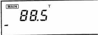
2) Push [SET] several times until "T" appears and blinks on the function display.
• Refer to p. 11 for SET mode details.
3) Rotate the tuning control to set the desired subaudible tone frequency.
- Subaudible tone frequency list.
| 67.0 | 91.5 | 118.8 | 156.7 | 210.7 |
| 71.9 | 94.8 | 123.0 | 162.2 | 218.1 |
| 74.4 | 97.4 | 127.3 | 167.9 | 225.7 |
| 77.0 | 100.0 | 131.8 | 173.8 | 233.6 |
| 79.7 | 103.5 | 136.5 | 179.9 | 241.8 |
| 82.5 | 107.2 | 141.3 | 186.2 | 250.3 |
| 85.4 | 110.9 | 146.2 | 192.8 | |
| 88.5 | 114.8 | 151.4 | 203.5 |
(Unit: Hz)
4) Push any switch except [SET] and [HI/LOW] to set the value and to exit SET mode.
5 MEMORY CHANNEL OPERATION
■ Selecting a memory channel
15 memory channels are available in each band for storing your often-used frequencies such as those used with repeaters, group calls, etc.
1) Push [BAND] to select VHF or UHF.
2) To select MEMORY mode, push [M/CALL] until "M" and a memory channel number appear on the function display.
$$ \begin{array}{c} \text {MAIN} \ 1 4 5. 6 8 0 \ - \quad \text {M} _ {1 5} \end{array} $$
3) Rotate the tuning control to select the desired memory channel.
• [UP] or [DN] can also be used for selecting.
- Memory channels "A" and "b" are used for the programmable scan edges.
- When an optional DTMF Remote is activated, the memory channel can be selected using a DTMF code. (pgs. 41\~43)
NOTE: When Up Switch Remote is activated, [UP] or [DN] cannot be used for frequency setting. See p. 29 for details.
■ Programming a memory channel
You can program the following data into a memory channel:
- Operating frequency
- Duplex information (DUP or DUP— and offset frequency)
- Tone squelch*1 or subaudible tone encoder ON/OFF and it's tone frequency*2
*1 An optional UT-67 is necessary for all versions.
*2 An optional UT-67 is necessary to change the frequency except for the U.S.A. version.
1) Select the memory channel for programming as described at left.
2) Push [V/MHz] to select VFO mode.
3) Set the desired data as described above to be programmed into the memory channel.
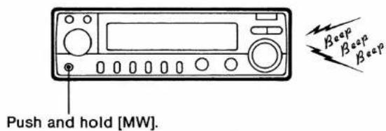
4) Push and hold [MW] for 2 sec. • If the beep tone is ON, 3 beeps alert you that the contents are programmed.
5) After the contents are written into the memory channel and you want to check them, push [M/CALL] to select the memory channel.
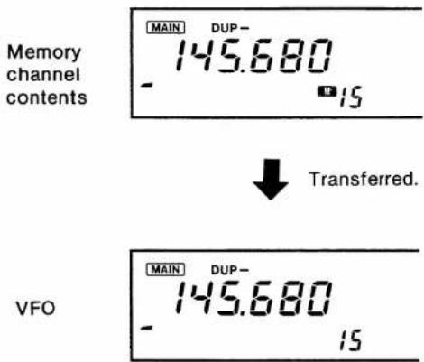
■ Transferring memory data
You can copy and transfer the contents of a memory channel into the VFO.
The function is especially useful when searching for signals around the memory channel frequencies.
1) Select the desired memory channel as described on p. 21.
2) Push and hold [MW] for 2 sec.
• The contents are transferred to the VFO.
- The transceiver goes into VFO mode automatically.
text_image
Push and hold [MW]. Beep Beep BeepCONVENIENT
Offset frequency, subaudible tone frequency, subaudible tone encoder ON/OFF setting and offset direction (DUP or DUP-) are simultaneously transferred into the VFO. You need not select a required repeater condition again.
If a memory or call channel contains an optional tone squelch setting, the setting is also transferred into the VFO.
text_image
Memory channel contents MAIN DUP- 145.680 - 15 Transferred. VFO MAIN DUP- 145.680 - 15
6
CALL CHANNEL OPERATION
■ Calling up a call channel
One call channel is equipped with each band. The call channels are programmable for storing your most-often-used frequencies. The call channels are separate from the memory channels.
1) Push [BAND] to select VHF or UHF.
2) Push [M/CALL] 1 or 2 times to indicate large "C."
• The call channel is selected.
3) To return to VFO mode, push [V/MHz].
To return to MEMORY mode, push [M/CALL].
■ Programming a call channel
1) Call up the desired band's call channel as described above.
- "C" appears.
2) Push [V/MHz] to select VFO mode.
• "C" changes to small "c."
3) Set the desired frequency (and duplex when required) to be programmed into the call channel.
4) Push and hold [MW] for 2 sec.
5) After the frequency is written into the call channel and you want to check the contents, push [M/CALL] to call up the call channel.
■ Transferring the contents of a call channel
The contents of a call channel can be transferred into a VFO.
1) Call up the desired band's call channel as described at left.
2) Push and hold [MW] for 2 sec. • The transceiver goes into VFO mode automatically. • "C" changes to small "c."
SCANNING OPERATION
7
Operating scan
There are 3 scan functions for your convenience as described below.
NOTE: When the optional tone squelch is activated during scan, the scan only stops when a signal with the same tone is received.
(1) Scan types
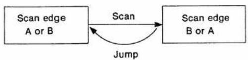
•PROGRAMMED SCAN
Repeatedly scans between 2 user-programmed scan edges, memory channel A and B.
flowchart
graph LR
    A["Scan edge A or B"] -->|Scan| B["Scan edge B or A"]
    B -->|Jump| A
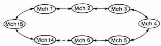
- MEMORY SCAN
Repeatedly scans all memory channels.
flowchart
graph TD
    A["Mch 1"] --> B["Mch 2"]
    B --> C["Mch 3"]
    C --> D["Mch 4"]
    D --> E["Mch 5"]
    E --> F["Mch 6"]
    F --> G["Mch 14"]
    G --> H["Mch 15"]
    H --> A
    style A fill:#f9f,stroke:#333
    style B fill:#f9f,stroke:#333
    style C fill:#f9f,stroke:#333
    style D fill:#f9f,stroke:#333
    style E fill:#f9f,stroke:#333
    style F fill:#f9f,stroke:#333
    style G fill:#f9f,stroke:#333
    style H fill:#f9f,stroke:#333
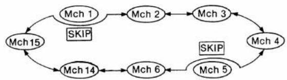
• MEMORY SKIP SCAN
Repeatedly scans all memory channels while skipping memory channels you do not wish to scan. This is an additional function of the memory scan as above.
flowchart
graph TD
    Mch1 --> Mch2
    Mch2 --> Mch3
    Mch3 --> Mch4
    Mch4 --> Mch5
    Mch5 --> Mch6
    Mch6 --> Mch14
    Mch14 --> Mch15
    Mch15 --> Mch1
    Mch1 -->|SKIP| Mch15
    Mch4 -->|SKIP| Mch14
7 SCANNING OPERATION
(2) Scan operation
Refer to the following table for scan operating procedure. However, before operating a scan, push [V SQL] or [U SQL] several times until noise is muted.
Push [BAND] or push and hold [BAND] to operate the other band while scanning.
(3) Setting program scan edges
Memorize scan edge frequencies for programmed scan in memory channels "A" and "b." Refer to "Programming a memory channel" on p. 21.
- "A" is next to memory channel 15.
• VHF and UHF scan edge frequencies must be separately programmed.
| SCAN TYPE | PRE-OPERATION | START | SCAN DIRECTION | RESUME CONDITION | STOP |
| Programmed scan | 1) Program scan edges as above.2) Select VFO mode. | Push and hold [UP] or [DN] on the microphone for 1 sec.When Up Switch Remote has been used, push [DN] to start the scan. (p. 29)When optional DTMF Remote is on standby, push [DN] to start the scan. (p. 41) | Use the tuning control to change the scan direction. | 5 types of the resume condition are available.Set the desired condition using SET mode in advance.(p. 26) | Push [UP] or [DN]. |
| Memory scan | Select MEMORY mode. | ||||
| Memory skip scan | 1) Set memory skip channels. (p. 26)2) Select MEMORY mode. |
USING SET MODE
- SETTING A RESUME CONDITION
V/U separate setting
$$ \begin{array}{c} \text { MAIN } \ 5 [ t - 1 5 \end{array} $$
1) Push [SET] several times until "SC" appears on the function display as shown above.
• Refer to p. 11 for SET mode details.
2) Rotate the tuning control to set the desired timer.
- SCt-5 : Scan resumes 5 sec. after the scan pauses.
- SCt-10 : Scan resumes 10 sec. after the scan pauses.
- SCt-15 : Scan resumes 15 sec. after the scan pauses.
- SCP-2 : Scan pauses until a signal disappears and resumes after 2 sec.
- SCI-EP : Scan pauses at a frequency that is not busy and resumes 2 sec. after a signal appears. It is useful to find a blank channel.
3) Push any switch except [SET] and [HI/LOW] to set the condition and to exit SET mode.
USING SET MODE
- SETTING A MEMORY SKIP CHANNEL
MEMORY mode → SET mode V/U separate setting
$$ - [ H - \quad \text { MAIN } ] $$
1) Push [M/CALL] until "M" and a memory channel number appear on the function display to select MEMORY mode.
2) Select the memory channel to be set as a skip channel. • The memory channels "A" and "b" cannot be set as a skip channel.
3) Push [SET] several times until "-CH-" blinks on the function display.
• Refer to p. 11 for SET mode details.
4) Rotate the tuning control to illuminate the skip indicator.
- "SKIP": The memory channel is skipped during memory scan.
• “”: The memory channel is scanned during memory scan.
5) Push any switch except [SET] and [HI/LOW] to set the condition and to exit SET mode.
8
PRIORITY WATCH OPERATION
■ Priority watch
Every 5 sec. priority watch monitors a watching frequency while you operate on the VFO frequency. There are 3 types of priority watch as described below.
NOTE: When an optional tone squelch is activated during priority watch, the watch only pauses when a signal with the same tone is received.
(1) Priority watch types
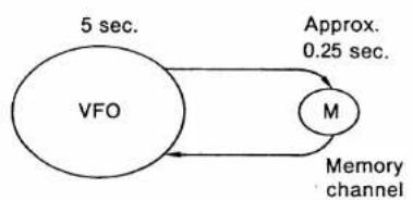
• VFO ↔ MEMORY CHANNEL
While operating in VFO mode, priority watch monitors the selected memory channel at 5 sec. intervals.
flowchart
graph LR
    A["VFO"] -->|5 sec.| B["M"]
    B -->|0.25 sec.| A
    style A fill:#fff,stroke:#000
    style B fill:#fff,stroke:#000
    note right of A: Approx. 0.25 sec.
    note right of B: Memory channel
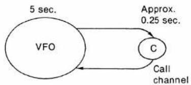
• VFO ← CALL CHANNEL
While operating on VFO mode, priority watch monitors the call channel at 5 sec. intervals.
flowchart
graph TD
    A["VFO"] -->|5 sec.| B["C"]
    B -->|Approx. 0.25 sec.| A
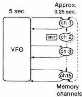
• VFO ↔ MEMORY SCAN
While operating on VFO mode, priority watch monitors all memory channels in sequence except memory channels programmed as skip channels.
flowchart
graph TD
    A["VFO"] --> B["ch1"]
    A --> C["ch2"]
    A --> D["ch3"]
    A --> E["ch15"]
    B --> F["Approx. 0.25 sec."]
    C --> F
    D --> F
    E --> F
    F --> G["Memory channels"]
    style A fill:#f9f,stroke:#333
    style B fill:#ccf,stroke:#333
    style C fill:#ccf,stroke:#333
    style D fill:#ccf,stroke:#333
    style E fill:#ccf,stroke:#333
    style F fill:#cfc,stroke:#333
(2) Priority watch operation
Refer to the following table regarding priority watch operation. However, before operating priority watch, push [V SQL] or [U SQL] several times until noise is muted.
Push [BAND] or push and hold [BAND] to operate on the other band while operating priority watch.
| PRIORITY WATCH TYPE | PRE-OPERATION | START | RESUME CONDITION | STOP |
| VFO Memory channel | Set the memory channel to be watched. | Push and hold [M/CALL] for 2 sec. “PRIO” appears. | 5 types of resume condition are available.Set the desired condition using SET mode in advance.(p. 26) | Push [M/CALL] to return to VFO mode.Push [SET] to return to SET mode.Push [PGR/CS] to return to MAIN band VFO mode and activate the optional pager function.Push [MW] to return to VFO mode and activate the optional voice synthesizer function. |
| VFO Call channel | Set the call channel to be watched. | |||
| VFO Memory scan | Start the memory scan. (p. 25) |
9
UP SWITCH REMOTE
The [UP] switch on the microphone can be programmed to control one of the switches on the front panel.
By using this function, you can easily and speedily access an often-used switch without stretching your arm.
WITH POWER ON
1) Turn power OFF.
2) Set [LOCK] on the microphone to the OFF position.
3) While pushing and holding [UP] on the microphone and the desired switch on the front panel, turn power ON.
• The [UP] switch functions as the desired switch.
- The [DN] switch functions as a scan start switch once the [UP] switch is programmed; and, the tuning control changes the scan direction.
4) To cancel this function, turn power OFF; then, while pushing and holding [UP], turn power ON.
EXAMPLE:
The following example shows how to access [BAND] using [UP] on the microphone.
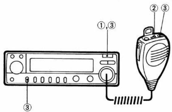
text_image
Diagram of an electronic device with labeled components including a digital display, a handheld device, and three numbered parts.1) Turn power OFF.
2) Set [LOCK] OFF.
3) While pushing and holding [UP] and [BAND], turn power ON.
• [UP] functions as [BAND].
• [DN] functions as the scan start switch.
SELECTIVE CALLING (optional)
Selective calling system
Each function shown below is useful for calling a specific station or for standby from a specific station. To operate these functions, an optional UT-55 or UT-67 is necessary. See p. 36 for installation.
| SYSTEM | DESCRIPTION | OPTION | |
| SELECTIVE CALLING | POCKETBEEP | This function alerts you with beep tones of approx. 30 sec. and a flashing “(1-2)” indicator when a signal with the same subaudible tone as that pre-programmed is received. | UT-67 |
| PAGER | This function displays the received ID code with beeps. ID codes can be independently programmed for each station. You can therefore choose to make a personal call or group call. | UT-55 | |
| COMMUNICATION | TONESQUELCH | When a signal including the same subaudible tone as that pre-programmed is received, the squelch opens. You can silently wait for a call from your group. | UT-67 |
| CODESQUELCH | When the same ID code as that pre-programmed is received, the squelch opens until the signal disappears. Or a group call can be selected in the same way as the pager function. | UT-55 |
The pocket beep and pager or code squelch cannot be used on 1 band at the same time. The tone squelch and pager or code squelch can be used at the same time.
• PAGER AND CODE SQUELCH (PERSONAL CALL)
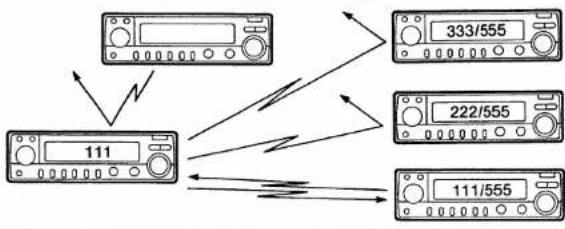
flowchart
graph TD
    A["111"] --> B["333/555"]
    A --> C["222/555"]
    A --> D["111/555"]
    B -->|Wireless Signal| A
    C -->|Wireless Signal| A
    D -->|Wireless Signal| A
• PAGER AND CODE SQUELCH (GROUP CALL)
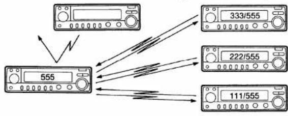
flowchart
graph TD
    A["555"] --> B["333/555"]
    A --> C["222/555"]
    A --> D["111/555"]
    B --> E["Signal Line"]
    C --> F["Signal Line"]
    D --> G["Signal Line"]
• POCKET BEEP AND TONE SQUELCH
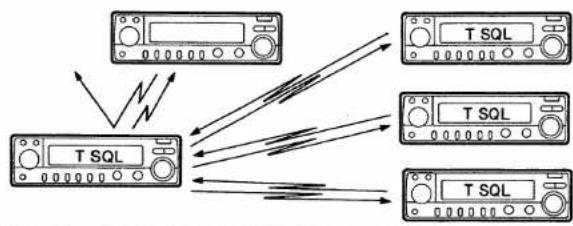
flowchart
graph TD
    A["T SQL"] -->|Wireless Signal| B["T SQL"]
    B --> C["Output"]
    D["T SQL"] -->|Wireless Signal| E["T SQL"]
    E --> F["Output"]
    G["T SQL"] -->|Wireless Signal| H["T SQL"]
    H --> I["Output"]
10 SELECTIVE CALLING
Code memory
The pager and code squelch functions require ID codes, and ID codes must be written in the code channels before operation.
An optional UT-55 DTMF ENCODER/DECODER UNIT is necessary for this operation.
(1) Pre-operation
1) Install optional UT-55 units in your group's transceivers.
- Some other Icom transceivers are compatible. Ask your Icom Dealer for details.
2) Decide the ID code of each transceiver and the group code in your group.
3) Decide whether to return to normal operation or code squelch operation after contact.
4) Program the ID code, group code, and other stations' ID codes as a transmit code.
- Your ID code should be programmed into code channel 0.
- Program "receive inhibit" on channels programmed as transmit codes.
(2) Code channel information
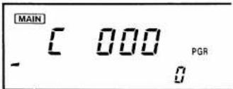
text_image
MAIN C 000 PGR - 0| CODE CHANNEL | PURPOSE | ACCEPT OR INHIBIT |
| 0 | Your ID code | “Accept” only |
| 1~5*1 | Other stations’ ID codes (transmit code) or group code | “Inhibit” for other stations’ ID codes.“Accept” for group code. |
| P | Memorizing space*2 | “Inhibit” only |
*1 Code channel 5 is also used to memorize the password of an optional External DTMF Remote. (p. 43)
*2 Channel P automatically memorizes a received ID code when receiving a pager call. The contents in channel P cannot be changed manually.
NOTE: Code channels 1\~5 can be programmed with other stations' ID codes or group code. We recommend that the same channel be used for group code programming.
(3) Programming a code
Programming can be performed on either band.
1) Push [PGR/CS] to select the pager function.
• "PGR" appears.
2) Push [SET] to call up a code channel.
• Code channel number blinks.
3) Rotate the tuning control to select the code channel number for programming.
4) Push [SET] or [HI/LOW] to select your desired digit to be programmed.
5) Rotate the tuning control to set the digit.
6) Repeat steps 4 and 5 until the code channel is completed.
7) Push [PGR/CS] to select "receive accept" or "receive inhibit." See at right for details.
8) When writing into other code channels, push [SET] or [HI/LOW] until the code channel number blinks; then repeat steps 3\~7.
9) Push any switches except [PGR/CS], [HI/LOW] or [SET] to set the value and to return to the previous mode.
- SETTING "RECEIVE ACCEPT" OR "RECEIVE INHIBIT"
Code channels 1\~5 can be programmed as "receive accept" or "receive inhibit."
- During "receive accept," the skip indicator is not illuminated; and, calls are accepted when the transceiver receives a signal with a code identical to that in the code channel.
- During "receive inhibit," the skip indicator is illuminated; and, calls are rejected when the transceiver receives a signal with a code identical to that in the code channel.
The code channel that stores your group's code should be programmed as "receive accept." The code channels that store other stations' ID codes (transmit codes) should be programmed as "receive inhibit."
For setting the condition, see item 7 at left.
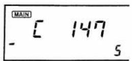
Receive accept
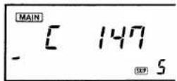
Receive inhibit
10 SELECTIVE CALLING
■ Pager operation
This function operates as part of a selective calling system. Note that the operations of the calling station and stand-by station are different. An optional UT-55 is necessary for this operation.
This function can be activated on the MAIN band only and cannot be activated while accessing the SUB band. (p. 15)
(1) Calling a specific station
1) Push [PGR/CS] to activate the pager function.
- "PGR" appears.
2) Select another station's ID code or group code (transmit code) from code channels 1\~5.
• See p. 32 for code channel programming.
3) Push the PTT switch to transmit a 7-digit DTMF code (transmit code + “*” + your ID code).
4) Wait for an answer back call.
- When the transceiver receives an answer back call, the function display shows the other station's ID or group code.
5) After confirming a connection, push [V/MHz]; then, push [PGR/CS] once to select code squelch or twice to select normal operation.
(2) Waiting for a call from a specific station
Waiting for a pager call is possible on the MAIN band only.
1) Set the frequency on the MAIN band.
2) Push [PGR/CS] to activate the pager function.
- "PGR" appears.
- Push and hold [BAND] to access the SUB band.
3) When receiving a call with a correct code, the transceiver emits a beep and the function display shows the code ①, ② or ③ as follows:
① When called with your ID code: The function display shows the other station's ID code and "P."
② When called with your group code: The function display shows the group code and code channel number that is written in the group code.
③ When the other station's ID code is not received completely because of interference, etc.: The function display shows "E" and the last-used code or group code.
4) Push the PTT switch to send an answer back call.
- Your ID code is transmitted.
5) Push [PGR/CS] once to select code squelch or twice to select normal operation.
■ Code squelch operation
An optional UT-55 DTMF ENCODER/DECODER UNIT is necessary for this operation. This function can be activated on the MAIN band only and cannot be activated while accessing the SUB band. (p. 15)
(1) Pre-operation
1) Decide the ID code for each transceiver and the group code in your group.
2) Program your ID code, group code, and the other stations' ID codes as transmit codes. See p. 31 for details.
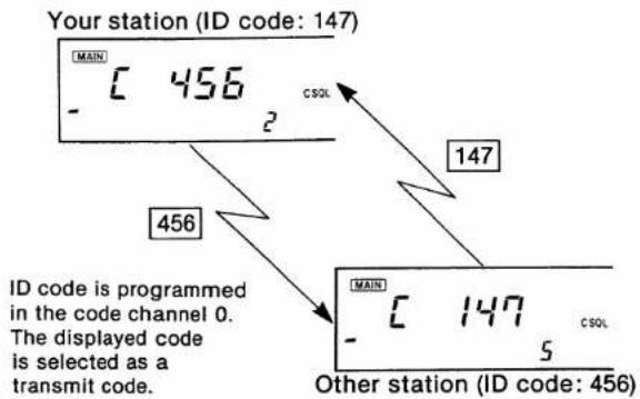
• CODE SQUELCH OPERATION EXAMPLE
text_image
Your station (ID code: 147) MAIN 456 CSOL 147 456 MAIN 147 CSOL Other station (ID code: 456) ID code is programmed in the code channel 0. The displayed code is selected as a transmit code.(2) Code squelch operation
1) Set the operating band and frequency.
2) Push [PGR/CS] 1 or 2 times to indicate "C SQL."
3) Push [SET] to call up a code channel.
• Code channel number blinks.
4) Rotate the tuning control to select another station's ID code or group code from code channels 1\~5.
• See p. 32 for code channel programming.
5) Push the PTT switch to transmit the 3-digit transmit code.
- When the transmit code is the same as the other station's ID code or group code, the other station's code squelch opens.
6) When your ID code or pre-programmed group code is received, your code squelch opens until the signal disappears.
7) Operate the transceiver for normal communications.
8) To cancel the code squelch function, push [PGR/CS].
NOTE: Make sure the code channel is correct when operating code squelch after using the pager function.
■ Pocket beep function
This function is used for waiting for a call from a specific station. When the transceiver receives a signal with the same subaudible tone as that pre-programmed, the transceiver emits beeps.
An optional UT-67 TONE SQUELCH UNIT is necessary for this operation. The calling station must set the tone squelch function. This function can be activated on both bands simultaneously.
1) Set the operating band and frequency.
2) Set a subaudible tone frequency using SET mode. See p. 20 for details.
3) Push [PGR/CS] until "PGR" or "C SQL" disappears while the optional pager or code squelch is activated.
4) Push [T/T.SQL] until "T SQL (●)" appears.
5) When a signal with the correct tone is received, the transceiver emits beeps for 30 sec. and flashes “(1·1).”
6) Push [T/T.SQL] to stop the beeping and flashing.
• The tone squelch function is automatically activated.
■ Tone squelch function
An optional UT-67 TONE SQUELCH UNIT is necessary for this operation. This function can be activated on both bands simultaneously.
1) Set the operating band and frequency.
2) Set a subaudible tone frequency using SET mode. See p. 20 for details.
3) Push [T/T.SQL] until "T SQL" appears.
4) When a signal with the correct tone is received, the squelch opens and the signal can be heard.
- When an incorrect tone frequency is received, the squelch does not open. However, the busy indicator appears.
- Push and hold [V SQL] or [U SQL] to open the squelch manually.
5) Operate the transceiver for normal communications.
6) To cancel the tone squelch function, push [T/T.SQL].
CONVENIENT
Tone squelch with a tone frequency can be programmed in a memory channel. Therefore, SET mode is not necessary once a memory is programmed.
OPTIONAL UNIT INSTALLATION
There are 3 types of optional internal units available.
• UT-55 DTMF ENCODER/DECODER UNIT
Allows you to operate the pager and code squelch function. Necessary for an optional Mic Remote and External DTMF Remote.
• UT-66 VOICE SYNTHESIZER UNIT
Announces the operating band frequency in English or Japanese.
• UT-67 TONE SQUELCH UNIT
Allows you to operate a repeater (this requires a subaudible tone for access), the pocket beep function or the tone squelch function.
For installation, proceed as follows:
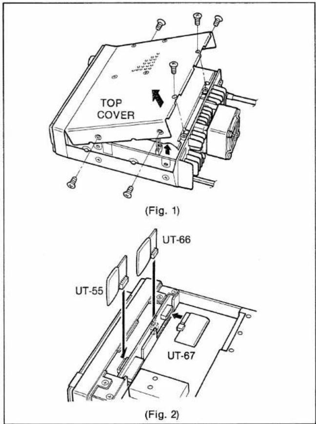
1) Remove 6 screws then remove the top cover as shown in the diagram at right. (Fig. 1)
2) Install the optional unit as shown in the diagram at right. (Fig. 2)
3) For the U.S.A. version, replace the UT-67 with the built-in TONE UNIT.
4) Replace the top cover and screws.
text_image
TOP COVER (Fig. 1) UT-66 UT-55 UT-67 (Fig. 2)12 HM-56 ADVANCED FUNCTIONS (U.S.A. and Asia versions)
The HM-56 HAND MICROPHONE is equipped with 14 DTMF memory channels and a re-dialing function for auto dialing. Up to a 22-digit telephone number, etc., can be memorized into each DTMF memory channel.
NOTE: Set [LOCK] on the microphone to the OFF position to use the HM-56 functions.
■ Mode types
The HM-56 has 4 different mode types as follows:
① NORMAL mode
A DTMF code is transmitted when a digit key is pushed.
② MEMORY WRITE mode
Used when writing DTMF codes into a DTMF memory channel in the HM-56.
• The active indicator blinks fast.
③ MEMORY READ mode
Used when reading DTMF codes from a DTMF memory channel in the HM-56.
• The active indicator lights continuously.
④ RE-DIAL mode
Used when recalling the last-transmitted DTMF codes.
• The active indicator blinks slowly.
■ Writing a DTMF code
1) Push [MW] on the microphone to select the MEMORY WRITE mode.
• The active indicator blinks fast.
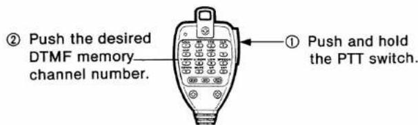
2) While pushing and holding the PTT switch, push the desired DTMF memory channel number [1]\~[0] or [A]\~[D] on the microphone. Do not release the PTT switch until step 4.
• The active indicator goes out.
text_image
② Push the desired DTMF memory channel number. ① Push and hold the PTT switch.3) While pushing the PTT switch, push the desired keys.
- Up to 22 digits can be memorized.
4) Release the PTT switch.
• The active indicator blinks fast.
5) To write other memory channels, repeat steps 2\~4.
6) Push [MW] on the microphone to return to NORMAL mode.
• The active indicator goes out.
■ Memory data erasing
1) Push [MW] on the microphone to select the MEMORY WRITE mode.
• The active indicator blinks fast.
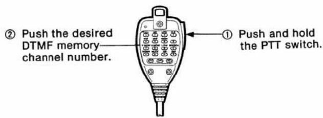
2) While pushing and holding the PTT switch, push the desired DTMF memory channel number [1]\~[0] or [A]\~[D] on the microphone.
• The active indicator goes out.
text_image
② Push the desired DTMF memory- channel number. ① Push and hold the PTT switch.3) Release the PTT switch.
• The active indicator blinks fast.
4) Push [MW] on the microphone to return to NORMAL mode.
• The active indicator goes out.
■Transmitting memory data
1) Push [MR] to select the MEMORY READ mode.
• The active indicator lights.
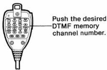
2) Push the desired DTMF memory channel number [1]\~[0] or [A]\~[D].
• The memorized DTMF code is automatically transmitted.
• The active indicator blinks while transmitting.
text_image
Push the desired DTMF memory channel number.3) Push [MW] to return to NORMAL mode.
• The active indicator goes out.
12 HM-56 ADVANCED FUNCTIONS
■ Re-dial function
The HM-56 automatically memorizes the last-transmitted DTMF code for re-dialing.
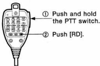
(1) Manual re-dialing
1) Push and hold the PTT switch.
• The active indicator does not light or blink.
2) Push [RD] to transmit the last-transmitted DTMF codes while pushing the PTT switch.
- The active indicator blinks while transmitting the DTMF code.
text_image
① Push and hold the PTT switch. ② Push [RD].(2) Auto re-dialing
The last-transmitted DTMF code can be automatically transmitted at each push of the PTT switch.
1) Push [RD] to select the RE-DIAL mode.
• The active indicator blinks slowly.
2) At each push of the PTT switch, the last-transmitted DTMF code is transmitted.
3) Push [RD] to return to NORMAL mode. • The active indicator goes out.
(3) Writing a re-dial memory
The last-transmitted DTMF codes are automatically written into a re-dial memory. You can manually write DTMF codes into the re-dial memory channel, if desired.
Push [RD] instead of the DTMF memory channel number key in "Writing a DTMF code" step 2. (p. 37)
■ 1750 Hz tone call
Using the HM-56, you can access a repeater that requires a 1750 Hz tone.
1) Push [MR] to select the MEMORY READ mode.
• The active indicator lights.
2) Transmit a 1750 Hz tone as follows:
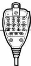
- Push and hold [#] to transmit a 1750 Hz tone continuously.
- Push [*] to transmit a 1750 Hz tone for approx. 0.5 sec.
Push [*] to transmit a 1750 Hz tone for—approx. 0.5 sec.
Push [#] to transmit -a 1750 Hz tone continuously.
3) Push [MW] to return to NORMAL mode.
• The active indicator goes out.
■ HM-56 CPU resetting
NOTE: CPU resetting CLEARS all memorized information in the microphone.
1) Turn the transceiver power OFF.
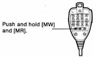
2) Push and hold [MW] and [MR] on the microphone.
3) Turn the transceiver power ON to reset the CPU in the microphone.
text_image
Push and hold [MW] and [MR].4) Release [MW] and [MR].
13 OPTIONAL DTMF REMOTE
The transceiver can be remotely controlled using DTMF signals. There are 2 remote control functions as follows.
- Mic DTMF Remote
- External DTMF Remote
Mic DTMF Remote
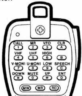
To operate Mic DTMF Remote, an HM-56 and an optional UT-55 are necessary. The HM-56 is an optional microphone for the Australia, Europe and Italy versions.
1) Attach the supplied microphone sheet to the HM-56 keyboard and connect it to the microphone connector.
text_image
CALL MR VFO CLR 1 2 3 A VHF UHF HIGH B 4 3 6 B V-MONI U-MONI LOW SPEECH 7 8 9 C DOWN MUTE UP ENT * 0 # D MW MR RDHM-56 rear panel
2) Push and hold [PGR/CS] until "REMOTE" appears to select standby for the remote control.
3) Push [UP] on the microphone to activate Mic DTMF Remote.
- [LOCK] on the microphone must be set OFF.
- "REMOTE" blinks.
4) Push the desired key on the microphone as described at right.
5) Push [UP] again to cancel the function.
- "REMOTE" stops blinking. The transceiver enters the standby condition for remote control.
6) Push and hold [PGR/CS] until "REMOTE" disappears to cancel standby for the remote control.
NOTE 1: Up Switch Remote cannot be activated while "REMOTE" lights or blinks.
NOTE 2: Scan cannot operate while "REMOTE" blinks. [DN] starts scanning when "REMOTE" lights.
NOTE 3: The tuning control and all switches except [PGR/CS] are locked while "REMOTE" blinks.
| KEY | DESCRIPTION | KEY | DESCRIPTION |
| [1] (CALL) | Selects CALL CHANNEL mode for the MAIN band. | [*] (DOWN) | Changes the operating frequency or memory channel downward in preset tuning steps. |
| [2] (MR) | Selects MEMORY mode for the MAIN band. | [A] (CLR) | Clears input digits and retrieves the previous key input. |
| [3] (VFO) | Selects VFO mode for the MAIN band. | ||
| [4] (VHF) | Selects VHF for the MAIN band. | [B] | Used for External DTMF Remote. (p. 43) |
| [5] (UHF) | Selects UHF for the MAIN band. | [C] (SPEECH) | Announces the MAIN band frequency when an optional UT-66 is installed. |
| [6] (HIGH) | Selects high power for MAIN band. | [D] (ENT) | Sets the transceiver to enter a frequency or memory channel number in 10 kHz tuning steps. |
| [7] (V • MONI) | Opens and closes the VHF squelch. | ||
| [8] (U • MONI) | Opens and closes the UHF squelch. | [0]~[9] (after pushing [D]) | Enters a frequency up to the 10 kHz digit*1 or enters memory channels (1~15, A and B*2). |
| [9] (LOW) | Selects low power 1 for MAIN band. | ||
| [0] (MUTE) | Mutes audio signals on both bands. | ||
| [#] (UP) | Changes the operating frequency or memory channel upward in preset tuning steps. |
*1 When the entered frequency is out of the frequency coverage, the input digit will be cleared.
*2 Push [1] then [6] for memory channel A; push [1] then [7] for memory channel B.
EXAMPLE: Setting the operating frequency at 145.80 MHz.
1) Push [4]; Selects VHF band for MAIN band.
2) Push [3]; Selects VFO mode.
3) Push [D]; Enters direct input condition.
4) Push [1], [4], [5], [8] and [0]; Frequency is set.
EXAMPLE: Selecting the operating memory channel to 15 (UHF).
1) Push [5]; Selects UHF band for MAIN band.
2) Push [2]; Selects MEMORY mode.
3) Push [D]; Enters direct input condition.
4) Push [1] and [5]; Memory channel is selected.
OPTIONAL DTMF REMOTE
■ External DTMF Remote
To operate External DTMF Remote, an optional UT-55 and a 144 MHz or 430 (440) MHz transceiver with a DTMF encoder are necessary.
(1) Pre-operation
1) Set the MAIN band frequency for operation and the SUB band frequency for receiving of a DTMF control signal.
- An optional tone squelch function can be used for SUB band to increase remote control reliability.
- Set the para-watch condition when using the same band for External DTMF Remote. (p. 44)
2) Program a 3-digit password into code channel 5, if required. (p. 32)
- The code channel 5 has been programmed "000" as initial value. If you do not require the password, set the channel as "receive inhibit."
3) Prepare a transceiver used as a controller:
- Set the operating frequency equal to the SUB band frequency of the IC-2410A/E/H.
- Turn ON the subaudible tone encoder and set the tone frequency when the IC-2410A/E/H uses an optional tone squelch function.
(2) Operation
1) Push and hold [PGR/CS] until "REMOTE" appears to select standby for the remote control.
2) From the controller transceiver, transmit a DTMF code to activate External DTMF Remote as follows.
① When a password has been set, push [B], the 3-digit password and [#].
② When a password has not been set, push [B] and [#].
- "REMOTE" and "SUB" blink.
3) Transmit the following DTMF code to control from the controller transceiver. See p. 42 for details.
| KEY | FUNCTION | KEY | FUNCTION | KEY | FUNCTION |
| [1] | CALL | [9] | LOW | [D] | ENT |
| [2] | MR | [#] | UP | [0]§[9] | Input a numeral after pushing [D]. |
| [3] | VFO | [*] | DOWN | ||
| [6] | HIGH | [A] | CLR |
4) To cancel the function, push [B] and [*].
• These will be transmitted as a DTMF code.
- "REMOTE" stops blinking and "SUB" disappears. The transceiver returns to standby for the remote control.
5) Push and hold [PGR/CS] until "REMOTE" disappears to cancel standby for the remote control.
PARA-WATCH 14
Para-watch
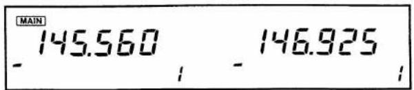
The IC-2410A/E/H can receive 2 frequencies simultaneously on the same band. Performing the following procedure enables the transceiver to receive a VHF signal at "U" section or a UHF signal at "V" section. All functions except for transmitting can be activated on the expanded frequency.
text_image
MAIN 145.560 146.925 - - -Expanded frequency
(1) Para-watch setting
WITH POWER ON
1) Turn power OFF.
2) While pushing [BAND], turn power ON. Then release the switch.
- Para-watch condition is activated.
3) To cancel this condition, reset the CPU. See p. 46 for details.

text_image
Push and hold [BAND] [POWER](2) Para-watch note
① Transmitting is not possible on the expanded frequency.
- When the PTT switch is pushed, the frequency readout shows "oFF."
② Receiver performance is reduced when operating on the expanded frequency.
③ The S-meter indication at the expanded frequency may differ from regular indication.
④ To use programmed scan through the expanded frequency, reset the scan edge frequencies.
⑤ The SUB band receiver circuit will be cut off when transmitting and when operating 2 frequencies on 1 band.
• The SUB band squelch indicator flashes in sequence.
⑥ The RF attenuator simultaneously activates while receiving 2 frequencies on 1 band.
15 MAINTENANCE
Troubleshooting
| PROBLEM | POSSIBLE CAUSE | SOLUTION | REF. |
| No power comes on. | Power connector has a poor contact.Polarity of the power connection is reversed.Blown fuse. | Check the connector pins.Reconnect the power cable observing the proper polarity.Check the cause, then replace the fuse. | p. 8p. 46 |
| No sound comes from the speaker. | The squelch is set too high.The optional tone or code squelch is turned ON. | Set the squelch at the lowest level.Turn OFF the tone or code squelch. | p. 13 pgs. 34, 35 |
| Sensitivity is low and only strong signals are audible. | Antenna feedline or the soldering of antenna connector is cut or short circuited. | Check, and if necessary, replace the feedline or solder the antenna connector again. | p. 9 |
| No contact possible with another station. | The transceiver is set to semi-duplex.The other station is using the tone or code squelch. | Set to simplex.Turn ON the tone or code squelch. (UT-67 or UT-55 is necessary.) | p. 17 pgs. 34, 35 |
| Repeater cannot be accessed. | Wrong offset frequency is programmed.Wrong subaudible tone frequency is programmed. | Correct the offset frequency.Correct the subaudible tone frequency. | p. 19p. 20 |
| Frequency cannot be set. | The lock function is activated. | Turn OFF the function. | p. 13 |
| Scan does not operate. | Squelch is open.Scan edge A equals B (for programmed scan).All memory channels are programmed as skip channels (for memory scan). | Set the squelch at the desired level.Reset scan edges.Cancel the memory skip function in the desired channel. | p. 25p. 25p. 26 |
| All programmed memories have been erased. | The CPU mulfuctions.Backup battery is empty. | Reset the CPU.Send the transceiver to an authorized Icom Dealer or Service Center to replace the backup battery. | p. 46p. 46 |
CPU resetting
The function display may occasionally display erroneous information, (e.g., when first applying power). This may be caused externally by static electricity or other factors.
If this problem occurs, turn power OFF. After waiting a few seconds, turn power ON again. If the problem continues, perform the following procedure.
NOTE: CPU resetting CLEARS all memory information, and initializes all values.
1) Turn power OFF.
2) While pushing [SET] and [MW], turn power ON.
- All segments appear on the function display, and the CPU is reset.
Cleaning
If the transceiver becomes dusty or dirty, wipe it clean with a dry, soft cloth.
AVOID the use of chemical agents such as benzine or alcohol, as they can damage the transceiver surfaces.
■ Fuse replacement
If the fuse blows or the transceiver stops functioning, find the source of the problem if possible, and replace the damaged fuse with a new, rated fuse as shown in the diagram below.
- REPLACING A FUSE
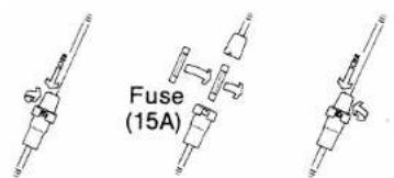
text_image
Fuse (15A)■ Backup batteries
The IC-2410A/E/H and HM-56 are equipped with separate lithium backup batteries for retaining memory information.
The life of the lithium backup batteries is usually more than 5 years. When the batteries are exhausted, the transceiver operates normally but the CPU cannot retain memory information.
NOTE: DO NOT attempt to replace the backup batteries yourself. They can be replaced only by an authorized Icom Dealer or Service Center.
16 SPECIFICATIONS
GENERAL
• Frequency coverage
| VERSION | VHF | UHF |
| U.S.A. | 144.000~148.000 (Tx)136.000~174.000*1(Rx) | 440.000~450.000 |
| Italy | 144.000~148.000 (Tx)136.000~174.000*1(Rx) | 430.000~440.000 (Tx)400.000~479.000*2(Rx) |
| Europe | 144.000~146.000 | 430.000~440.000 |
| Australia | 144.000~148.000 | 430.000~440.000 |
| Asia | 144.000~148.000 (Tx)136.000~174.000*1(Rx) | 430.000~440.000 |
*1 Specifications guaranteed 144.000\~148.000 MHz. Unit: MHz
*2 Specifications guaranteed 430.000\~440.000 MHz.
- Mode
- Antenna impedance
• Power supply requirement - Usable temperature range
- Dimensions
- Weight
TRANSMITTER
- Modulation system
• Max. frequency deviation - Spurious emissions
- Microphone impedance
: FM (F3)
: 50 Ω nominal
: 13.8 V DC ± 15 %
-10^ +60^ (+14^ +140^)
: 140 (W) × 40 (H) × 174.5 (D) mm
5.5 (W) × 1.6 (H) × 6.9 (D) in (projections not included)
: 1.35 kg (3.0 lb)
: Variable reactance frequency modulation
: ±5 kHz
: Less than -60 dB
:600Ω
• Output power and current drain (at 13.8 V DC)
| IC-2410A/E | IC-2410H | ||||
| POWER | CURRENT | POWER | CURRENT | ||
| VHF | High | 25 W | 7.0 A | 45 W | 10.5 A |
| Low 2 | 10 W | 4.5 A | 10 W | 5.5 A | |
| Low 1 | 1 W | 2.5 A | 5 W | 4.0 A | |
| UHF | High | 25 W | 8.0 A | 35 W | 10.5 A |
| Low 2 | 10 W | 5.0 A | 10 W | 6.0 A | |
| Low 1 | 1 W | 3.0 A | 5 W | 4.5 A | |
RECEIVER
- Receive system
• Intermediate frequencies
: Double-conversion superheterodyne
: 1st 17.2 MHz (VHF)
30.85 MHz (UHF)
2nd 455 kHz
: Less than 0.16 μV for 12 dB SINAD
: Less than 0.13 μV
: More than 15 kHz/−6 dB
Less than 30 kHz/−60 dB
: More than 15 kHz/−6 dB
Less than 30 kHz/−60 dB
: More than 60 dB
: More than 2.4 W at 10 % distortion with an 8 Ω load
: Max. audio output 1.8 A
Squelched 1.2 A
All stated specifications are subject to change without notice or obligation.
Count on us!
A-5153H-1EX-①
Printed in Japan
Copyright © 1991 by Icom Inc.
Icom Inc.
6-9-16, Kamihigashi, Hirano-ku, Osaka 547, Japan