
IC-3210A - Empfänger ICOM - Kostenlose Bedienungsanleitung
Finden Sie kostenlos die Bedienungsanleitung des Geräts IC-3210A ICOM als PDF.


Benutzerfragen zu IC-3210A ICOM
0 Frage zu diesem Gerät. Beantworten Sie die, die Sie kennen, oder stellen Sie Ihre eigene.
Eine neue Frage zu diesem Gerät stellen
Laden Sie die Anleitung für Ihr Empfänger kostenlos im PDF-Format! Finden Sie Ihr Handbuch IC-3210A - ICOM und nehmen Sie Ihr elektronisches Gerät wieder in die Hand. Auf dieser Seite sind alle Dokumente veröffentlicht, die für die Verwendung Ihres Geräts notwendig sind. IC-3210A von der Marke ICOM.
BEDIENUNGSANLEITUNG IC-3210A ICOM

text_image
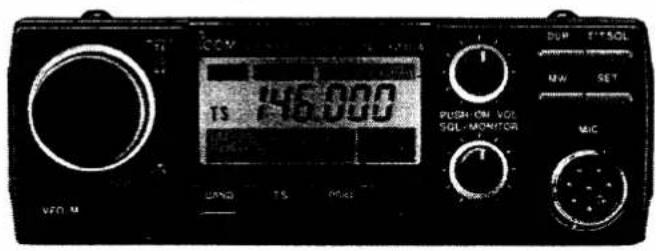
ICOMINSTRUCTION MANUAL
DUAL BAND
FM TRANSCEIVER
IC-3210A
IC-3210E
text_image
DCV 15 000 PUSH ON VGA SGL MONITOR VFD M UAND TS MAX DUP T'SOL MW SET MICIcom Inc.
CAUTIONS
Before using the transceiver, read all instructions carefully and completely.
SAVE THESE INSTRUCTIONS – This instruction manual contains important safety and operating instructions for the IC-3210A/E.
NEVER connect the transceiver to an AC outlet. This will ruin the transceiver.
NEVER connect more than 16 V DC power supplies or batteries to the transceiver. Check the source before connecting the power cable.
NEVER allow children to touch the transceiver during operation.
NEVER use or place the transceiver in areas with temperatures below -10^ (+14°F) or over +60°C (+150°F).
NEVER expose the transceiver to rain, snow or any liquids.
DO NOT place the transceiver in excessively humid environments.
AVOID placing the transceiver in direct sunlight, such as on the dashboard.
AVOID using the transceiver in excessively dusty environments.
BE CAREFUL! The heatsink may become hot when operating the transceiver continuously for long periods.
TABLE OF CONTENTS
CAUTIONS i
TABLE OF CONTENTS (THIS LIST) ..... ii
FOREWORD .... iii
UNPACKING....iii
1 FEATURES.... 1
2 PANEL DESCRIPTION.... 2
2-1 FRONT PANEL 2
2-2 FUNCTION DISPLAY 4
2-3 REAR PANEL 5
2-4 MICROPHONE 5
3 INSTALLATION 6
4 MODE CONSTRUCTION 9
5 BASIC OPERATION.... 11
5-1 FREQUENCY SETTING....11
5-2 RECEIVING. 12
5-3 TRANSMITTING....13
5-4 REPEATER OPERATION ..... 14
6 RELATED FUNCTIONS.... 16
6-1 FULL DUPLEX 16
6-2 CALL CHANNEL MODE 17
6-3 MEMORY MODE 18
6-4 SCAN FUNCTION....20
6-5 PRIORITY WATCH....25
6-6 DIMMER CONTROL 27
6-7 BEEP ON/OFF FUNCTION....27
6-8 LOCK FUNCTION. 27
7 POCKET BEEP AND TONE SQUELCH.....28
7-1 UT-40 INSTALLATION 28
7-2 POCKET BEEP....29
7-3 TONE SQUELCH 29
8 MAINTENANCE.... 30
8-1 TROUBLESHOOTING. 30
8-2 FUSE REPLACEMENT....31
8-3 CPU RESETTING....32
9 INSIDE VIEWS 33
10 SPECIFICATIONS 34
11 OPTIONS 35
FOREWORD
Thank you for purchasing the IC-3210A/E DUAL BAND FM TRANSCEIVER from Icom.
Please read this instruction manual thoroughly before operating your new IC-3210A/E. For further information, please feel free to contact your nearest Icom Dealer or Service Center.
UNPACKING
text_image
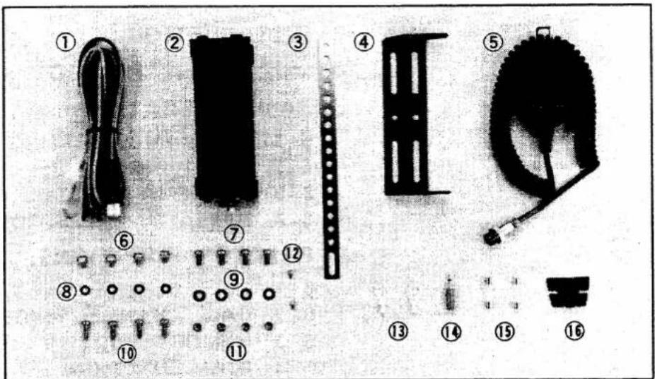
Exploded view diagram of a mechanical assembly with numbered parts for identificationAccessories included Qty.
① DC power cable ..... 1
② Mobile mounting bracket 1
③ Mounting support bracket 1
④ Angle bracket 1
⑤ Microphone* 1
⑥ Mounting bracket screws....4
⑦ Mounting screws (M5 x 12) 4
⑧ Spring washers (M5) 4
⑨ Flat washers (M5)....4
⑩ Mounting self-tapping screws 4
⑪ Nuts (M5) 4
⑫ Screws (M3 x 6)....2
⑬ Cable lugs 2
⑭ External speaker plug. 1
⑮ Fuses (15A) 2
⑯ Microphone hanger 1
* HM-12 (supplied with IC-3210A, Australia version) HM-14 (supplied with IC-3210A, U.S.A. version) HM-15 (supplied with IC-3210E)
FEATURES
1
TWO BANDS IN A COMPACT BODY
The IC-3210A/E gives you 2 m and 70 cm in one compact body. Operate two bands with one transceiver. The built-in duplexer allows one-antenna operation.
FULL DUPLEX CAPABILITY
Transmit on one band and receive on the other and you're operating with full duplex. Working full duplex is as easy as talking on the telephone.
SIMPLE PANEL DESIGN
The front panel is very simple: there are only three controls and eleven switches. The simple design makes operation easy — even when driving.
20 DOUBLE-SPACED MEMORY CHANNELS
The IC-3210A/E has 20 double-spaced memory channels. One space stores an operating frequency as well as all information required to work a repeater. When not working a repeater, the other space stores a frequency to be used for full duplex. Up to 40 channels can be used for simplex.
THREE SCANS
The IC-3210A/E has three scans: programmed scan, memory scan and selected band memory scan. Using the memory channel skip function, any number of memory channels can be skipped during a scan.
PRIORITY WATCH
Every five seconds, priority watch monitors another band VFO, a call channel, a memory channel, or all memory channels in succession while you work on the operating frequency.
POCKET BEEP
When the UT-40 (sold separately) is installed, the transceiver functions as a pager. When a received tone frequency equals the tone you've set, an alarm of 30 seconds is emitted over the speaker. This is especially convenient for busy schedules, etc.
MONITOR FUNCTION
The monitor function opens the squelch (also the tone squelch when the UT-40 is installed) without you rotating the [SQL/MONITOR] control.
2 PANEL DESCRIPTION
2-1 FRONT PANEL
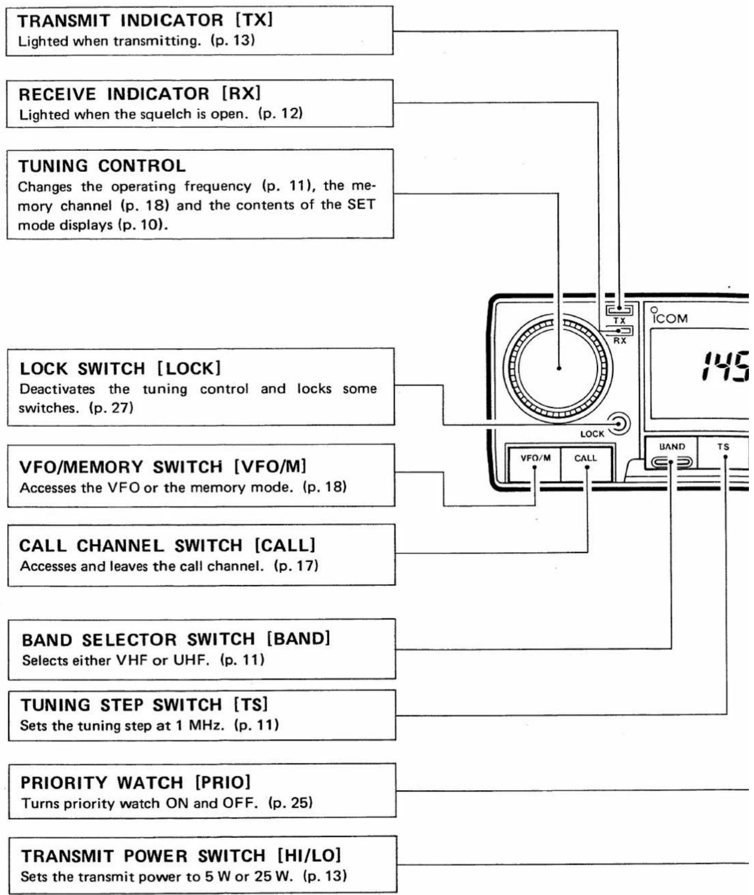
flowchart
graph TD
    A["TRANSMIT INDICATOR [TX"]
    Lighted when transmitting. (p. 13)] --> B["TUNING CONTROL"]
    C["RECEIVE INDICATOR [RX"]
    Lighted when the squelch is open. (p. 12)] --> B
    D["LOCK SWITCH [LOCK"]
    Deactivates the tuning control and locks some switches. (p. 27)] --> B
    E["VFO/MEMORY SWITCH [VFO/M"]
    Accesses the VFO or the memory mode. (p. 18)] --> B
    F["CALL CHANNEL SWITCH [CALL"]
    Accesses and leaves the call channel. (p. 17)] --> B
    G["BAND SELECTOR SWITCH [BAND"]
    Selects either VHF or UHF. (p. 11)] --> B
    H["TUNING STEP SWITCH [TS"]
    Sets the tuning step at 1 MHz. (p. 11)] --> B
    I["PRIORITY WATCH [PRIO"]
    Turns priority watch ON and OFF. (p. 25)] --> B
    J["TRANSMIT POWER SWITCH [HI/LO"]
    Sets the transmit power to 5 W or 25 W. (p. 13)] --> B
    B --> K["TRANSMIT INDICATOR TX"]
    B --> L["RECEIVE INDICATOR RX"]
    B --> M["TUNING CONTROL"]
    B --> N["LOCK SWITCH [LOCK"]]
    B --> O["VFO/MEMORY SWITCH [VFO/M"]]
    B --> P["CALL CHANNEL SWITCH [CALL"]]
    B --> Q["BAND SELECTOR SWITCH [BAND"]]
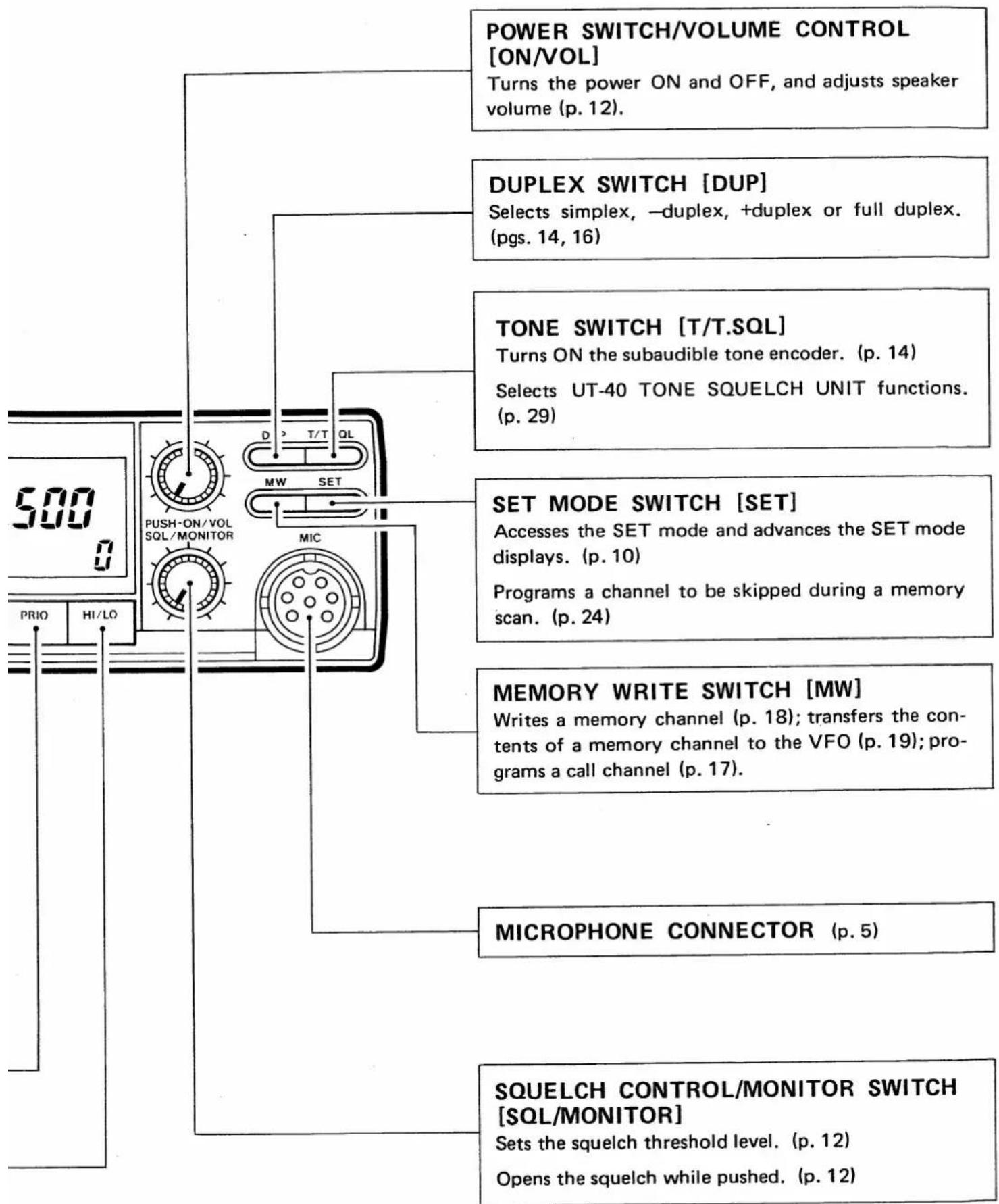
flowchart
graph TD
    A["500"] --> B["PUSH-ON/VOL SQL/MONITOR"]
    B --> C["D T/T QL"]
    C --> D["MW SET"]
    D --> E["SQUELCH CONTROL/MONITOR SWITCH [SQL/MONITOR"]]
    E --> F["SUELCH CONTROL/MONITOR SWITCH [SQL/MONITOR"]]
    B --> G["PRIO HI/LO"]
    C --> H["DUPLEX SWITCH [DUP"]]
    H --> I["Selects simplex, -duplex, +duplex or full duplex. (pgs. 14, 16)"]
    E --> J["TONE SWITCH [T/T.SQL"]]
    J --> K["Turns ON the subaudible tone encoder. (p. 14)"]
    E --> L["SET MODE SWITCH [SET"]]
    L --> M["Accesses the SET mode and advances the SET mode displays. (p. 10)"]
    L --> N["Programs a channel to be skipped during a memory scan. (p. 24)"]
    E --> O["MICROPHONE CONNECTOR (p. 5)"]
    E --> P["SUELCH CONTROL/MONITOR SWITCH [SQL/MONITOR"]]
    P --> Q["Sets the squelch threshold level. (p. 12)"]
    P --> R["Opens the squelch while pushed. (p. 12)"]
2 PANEL DESCRIPTION
2-2 FUNCTION DISPLAY
DUPLEX INDICATOR
"DUP—" or "DUP" appears when semi duplex is selected for repeater operation. (p. 14)
SPLIT INDICATOR
"SPT" appears when full duplex is selected. (p. 16)
PRIORITY INDICATOR
Appears during priority watch operation. (p. 25)
SPT DUP - TONE SQL
PRIO TS 146.000
LOW 1 5 9 M SKIP 18
TUNING STEP INDICATOR
Appears when a 1 MHz tuning step is selected with the [TS] switch. (p. 11)
LOW POWER INDICATOR
Appears when low power is selected with the [HI/LO] switch. (p. 13)
S/RF INDICATOR
Displays the strength of a received signal. (p. 12)
Displays relative output power selection when transmitting. (p. 13)
MEMORY INDICATOR
Appears when the memory mode is selected with the [VFO/M] switch. (p. 18)
TONE INDICATOR
"TONE" appears when the tone encoder is turned ON. (p. 14)
"SQL" appears when the UT-40 (sold separately) "pocket beep" function is activated. (p. 29)
"TONE SQL" appears when the UT-40 (sold separately) tone squelch function is activated. (p. 29)
FREQUENCY READOUT
Displays the operating frequency (except during the SET mode).
MEMORY CHANNEL READOUT
Displays the memory channel number. (p. 18)
Displays "C" when the call channel mode is selected with the [CALL] switch. (p. 17)
Displays "L" when the lock function is activated with the [LOCK] switch. (p. 27)
SKIP CHANNEL INDICATOR
Appears when a memory channel is programmed to be skipped during a memory scan. (p. 24)
2-3 REAR PANEL
POWER RECEPTACLE
Accepts 13.8V DC with the supplied DC cable. (p. 7)
EXTERNAL SPEAKER JACK
4 \~ 8 Ω speaker jack.
ANTENNA CONNECTOR
Connects a 50 Ω dual-band antenna with a PL-259 connector to the transceiver. (p. 8)

text_image
EXT SP ICOM DC13 6V ANT2-4 MICROPHONE
text_image
② ③ ④ HM-14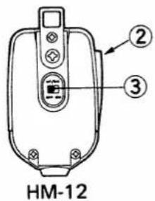
text_image
② ③ HM-12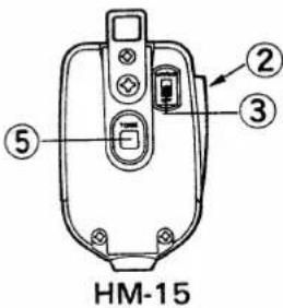
text_image
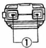
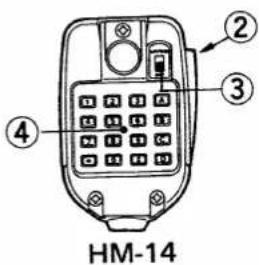
② ③ ⑤ HM-15① FREQUENCY UP/DOWN SWITCHES [UP] [DN]
Push either switch to change the operating frequency or a memory channel. (p. 11)
Push and hold either switch to start scanning. (pgs. 20 \~ 23)
③UP/DOWN ON/OFF SWITCH
Deactivates the [UP][DN] switches.
④DTMF KEYBOARD (HM-14 only)
Produces DTMF signals when the PTT switch is pushed. (p. 14)
⑤ TONE CALL SWITCH (HM-15 only)
Push and hold to transmit a 1750 Hz tone signal. (p. 14)
②PTT SWITCH
Push and hold to transmit. (p. 13)
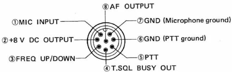
•MIC CONNECTOR (Front panel view)
text_image
⑧ AF OUTPUT ①MIC INPUT ②+8 V DC OUTPUT ③FREQ UP/DOWN ⑦GND (Microphone ground) ⑥GND (PTT ground) ⑤PTT ④T.SQL BUSY OUT3 INSTALLATION
(1) LOCATION
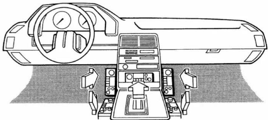
Select a location for the transceiver that does not interfere with driving in any way. We recommend the locations shown in the diagram below.
natural_image
Line drawing of a car cockpit with control panel and steering wheel (no text or symbols)LOCATION NOTES:
NEVER place the transceiver in direct sunlight.
NEVER place the transceiver where normal operation of the vehicle may be hindered or where it could cause bodily injury.
DO NOT place the transceiver where hot or cold air blows directly on it.
(2) MOUNTING
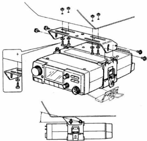
After mounting the transceiver, be sure all screws have been tightened.
●MOUNTING THE TRANSCEIVER
natural_image
Technical line drawing of an electronic device with mounting hardware and internal components (no text or symbols)1) Drill four holes where the mounting bracket is to be installed.
- Hole sizes:
approx. 5.5 \~ 6 mm when using nuts. approx. 2 \~ 3 mm when using self-tapping screws.
2) Insert the supplied screws, nuts and washers through the mounting bracket and tighten.
3) If the mounting location is not flat, use the supplied mounting bracket.
4) Adjust the angle for the clearest view of the function display.
(3) BATTERY CONNECTION
text_image
IC-3210A/E rear panel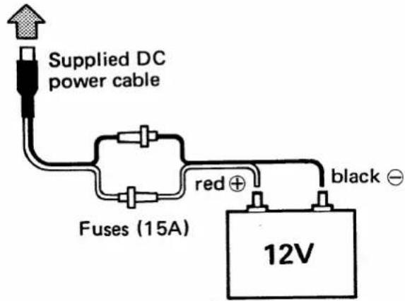
text_image
Supplied DC power cable Fuses (15A) red ⊕ black ⊖ 12V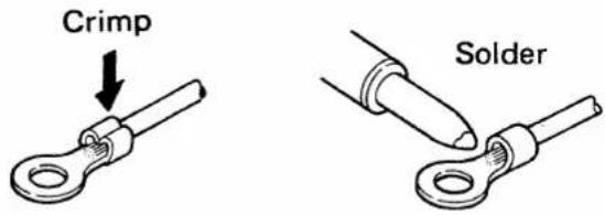
text_image
Crimp Solder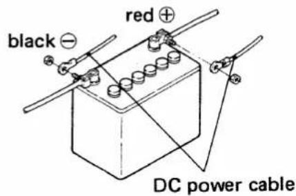
text_image
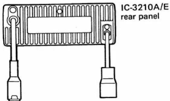
black red DC power cableCONNEC-TION NOTES: DO NOT connect the transceiver to a 24 V battery. DO NOT use the cigarette lighter socket for power connections. To prevent voltage drops, solder or crimp the cable lag when connecting the power cable to the battery.
(4) EXTERNAL POWER SUPPLY
Use a 13.8 V DC power supply with more than 8 A, such as the PS-45 AC POWER SUPPLY.
When using the transceiver as a base station, be sure the power supply is grounded. Use the heaviest gauge wire or strap available and make the connection as short as possible.
3 INSTALLATION
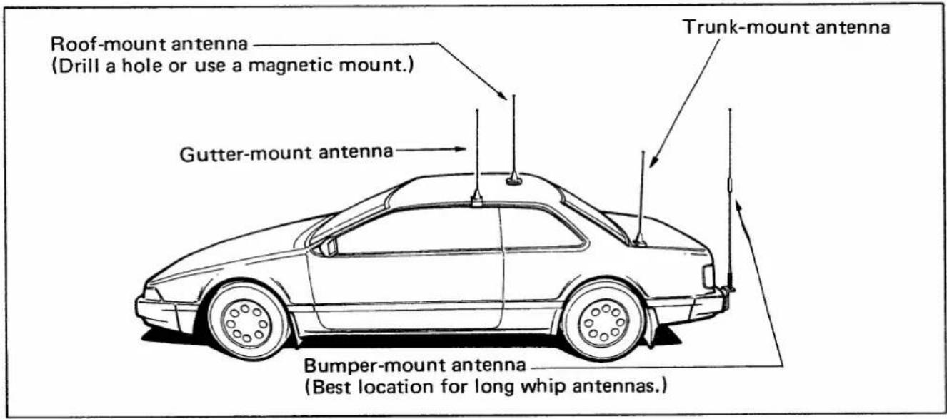
(5) ANTENNA LOCATION
A duplexer is built-in, enabling you to use a dual band antenna.
To obtain maximum performance from the transceiver, select a high-quality antenna and a good location for it.
text_image
Roof-mount antenna (Drill a hole or use a magnetic mount.) Gutter-mount antenna Trunk-mount antenna Bumper-mount antenna (Best location for long whip antennas.)(6) ANTENNA CONNECTOR
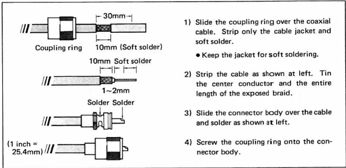
Use a PL-259 antenna connector.
text_image
Coupling ring 30mm 10mm (Soft solder) 10mm Soft solder 1~2mm Solder Solder (1 inch = 25.4mm) 1) Slide the coupling ring over the coaxial cable. Strip only the cable jacket and soft solder. ● Keep the jacket for soft soldering. 2) Strip the cable as shown at left. Tin the center conductor and the entire length of the exposed braid. 3) Slide the connector body over the cable and solder as shown at left. 4) Screw the coupling ring onto the connector body.(7) DUPLEXER
You can use a dual band antenna because a duplexer is installed in the IC-3210A/E. However, an external duplexer must be connected when using separate antennas for each band.
MODE CONSTRUCTION
4
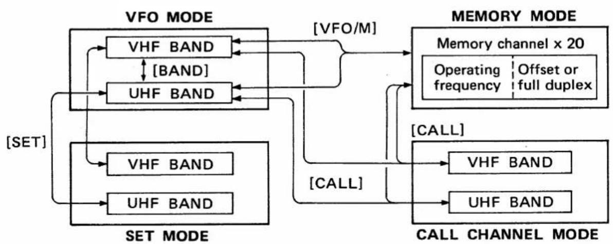
The IC-3210A/E has 4 different modes on each band for versatile, multi-function operations.
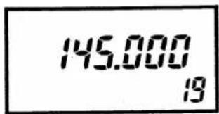
• VFO MODE
text_image
145.000 19This mode is used for normal operations on the VHF and UHF bands.
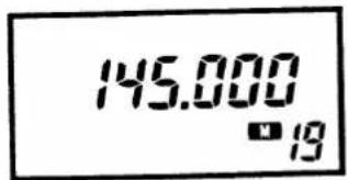
- MEMORY MODE
text_image
145.000 ■19This mode is used for operating the transceiver using memory channel contents. You can use 20 double-spaced memory channels. One space stores an operating frequency. The other space stores information required to work a repeater; when not working a repeater, the other space stores a frequency to be used for full duplex.
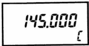
- CALL CHANNEL MODE
text_image
145.000 [This mode provides you with two channels separate from the memory channels. Each band has one call channel.
- SET MODE
text_image
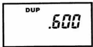
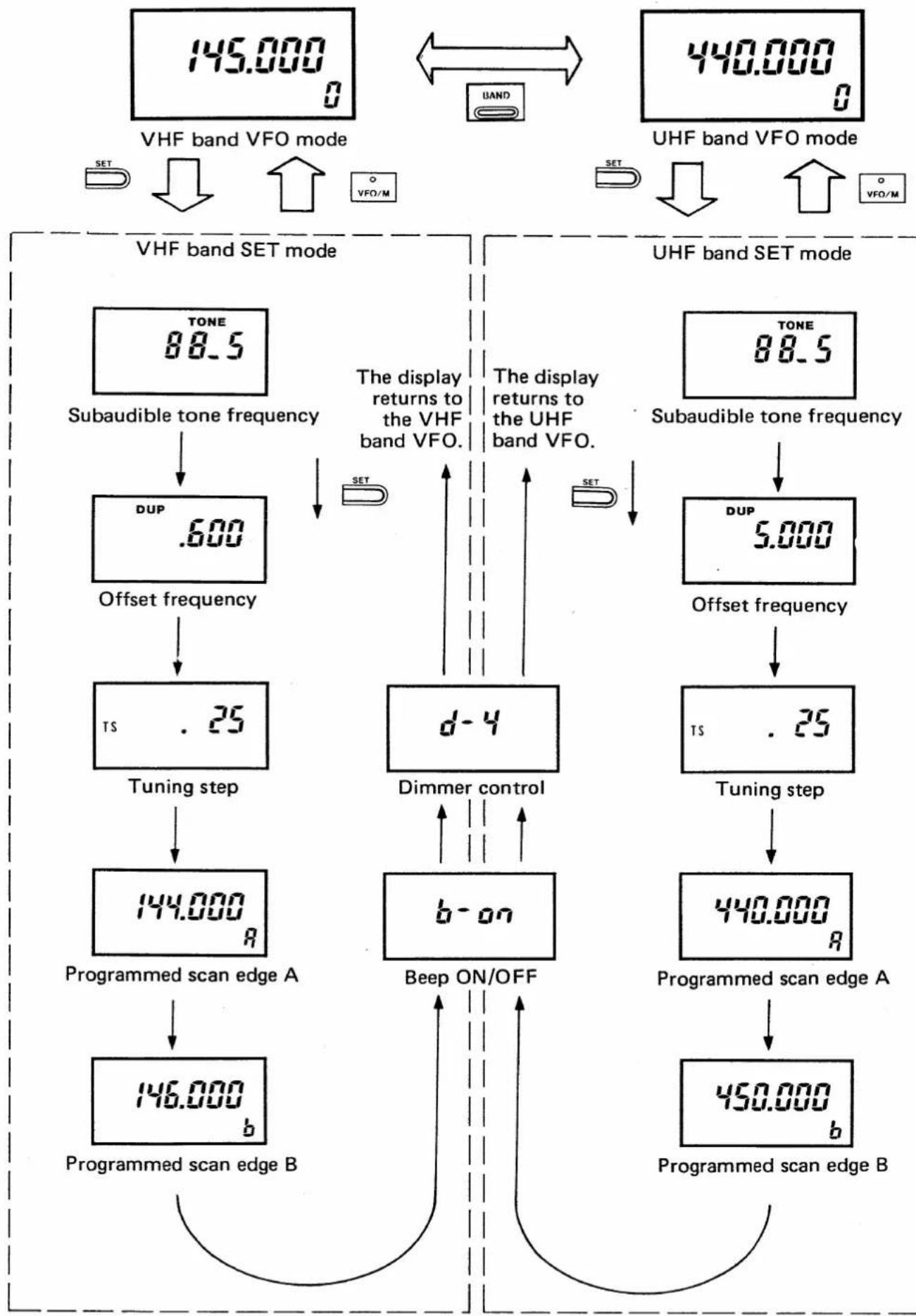
DUP .600Use the SET mode to program the data as described on p. 10.
To access the SET mode displays, push [SET] on the VFO mode. The display you last used appears.
■ MODE CONSTRUCTION CHART
flowchart
graph TD
    subgraph_VFO_MODE["Set Mode"]
        A1["VHF BAND"] --> A2["UBF BAND"]
        A2 --> A3["VFO/M"]
    end
    subgraph_SET_MODE["Set Mode"]
        B1["VHF BAND"] --> B2["UHF BAND"]
    end
    subgraph_MEMORY_MODE["CALL CHANNEL MODE"]
        C1["Memory channel x 20"] --> C2["Operating frequency"]
        C2 --> C3["Offset or full duplex"]
    end
    subgraph_CALL_CHANNEL_MODE["CALL Channel Mode"]
        D1["VHF BAND"] --> D2["UHF BAND"]
    end
    A1 <--> A2
    B1 <--> B2
    C1 <--> C2
    D1 <--> D2
    A3 <--> C3
    B3 <--> C4
    C4 <--> C5
4 MODE CONSTRUCTION
SET MODE CONSTRUCTION CHART
flowchart
graph TD
    A["VHF band VFO mode"] --> B["SET"]
    B --> C["Subaudible tone frequency"]
    C --> D["DUP .600"]
    D --> E["Offset frequency"]
    E --> F["Tuning step .25"]
    F --> G["Programmed scan edge A"]
    G --> H["146.000 b"]
    H --> I["Programmed scan edge B"]

    J["UHF band VFO mode"] --> K["SET"]
    K --> L["Subaudible tone frequency"]
    L --> M["DUP .5.000"]
    M --> N["Offset frequency"]
    N --> O["Tuning step .25"]
    O --> P["Programmed scan edge A"]
    P --> Q["450.000 b"]
    Q --> R["Programmed scan edge B"]

    style A fill:#f9f,stroke:#333
    style J fill:#f9f,stroke:#333
BASIC OPERATION
5
5-1 FREQUENCY SETTING
text_image
4) Set freq. 1) Power ON. 2) Select VFO. 3) Select band. 5) Push for 1 MHz.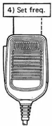
text_image
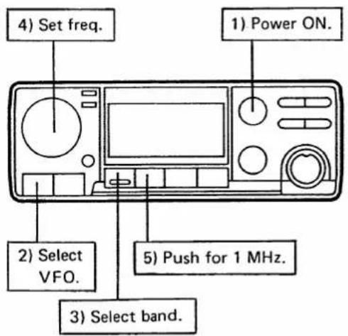
4) Set freq.Frequencies can be set with the tuning control or the microphone [UP] [DN] switches.
1) Push [ON/VOL] to turn ON the power.
2) If "M" or "C" appears on the function display push [VFO/M] to select the VFO mode.
3) Push [BAND] to select VHF or UHF.
4) Rotate the tuning control or push the [UP] or [DN] switch on the microphone to change the frequency.
- IC-3210A : 5, 10, 15, 20 or 25 kHz IC-3210E : 12.5 or 25 kHz
- Select a tuning step in the SET mode as described below.
• VHF and UHF tuning steps are programmed independently.
- To exchange IC-3210A tuning steps for IC-3210E tuning steps or vice-versa, reset the CPU (p. 32).
5) Push [TS] for a 1 MHz tuning step.
- "TS" appears when the 1 MHz step is selected.
- The tuning control changes the frequency in 1 MHz steps. [UP] and [DN] on the microphone do not.
USING SET MODE
■ TUNING STEP SELECTION
text_image
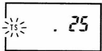
-TS . 25The display shows the 25 kHz tuning step.
1) Push [VFO/M] to access the VFO mode.
2) Push [BAND] to select VHF or UHF.
3) Push [SET] until "TS" flashes on the function display as shown at left.
4) Rotate the tuning control for the desired tuning step.
5) Push [VFO/M] to return to the VFO mode.
5 BASIC OPERATION
5-2 RECEIVING
text_image
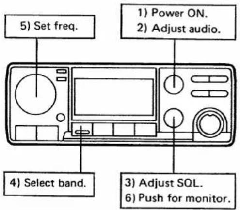
5) Set freq. 1) Power ON. 2) Adjust audio. 4) Select band. 3) Adjust SQL. 6) Push for monitor.1) Push [ON/VOL] to turn ON the power and rotate [SQL/MONITOR] maximum counterclockwise.
2) Rotate [ON/VOL] to the desired audio level.
3) Rotate [SQL/MONITOR] to the squelch threshold point.
4) Push [BAND] to select the desired band (VHF or UHF).
5) Set the desired frequency with the tuning control or the microphone [UP] [DN] switches.
- When a signal is received, audio is emitted from the speaker and the S/RF indicator displays the relative signal strength.
6) Push [SQL/MONITOR] to operate the monitor function, if desired.
5-3 TRANSMITTING
text_image
1) Select simplex. 2) Select power.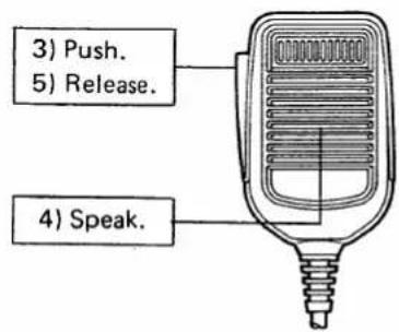
text_image
3) Push. 5) Release. 4) Speak.CAUTION: Transmitting without an antenna may damage the transceiver.
NOTE: To prevent interference, listen on the frequency before transmitting.
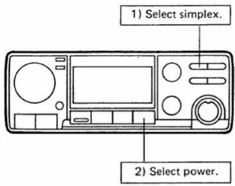
1) If "SPT," "DUP—" or "DUP" appears on the function display, push [DUP] until it disappears.
2) Push [HI/LO] to select the output power.
- HIGH : 25 W
LOW : 5 W ("LOW" appears on the function display.)
3) Push and hold the [PTT] switch on the microphone to transmit.
- The [TX] indicator lights and the S/RF indicator shows relative output power selection.
4) Speak into the microphone using your normal voice level.
- Do not hold the microphone too closely to your mouth or speak too loudly. This may distort the signal.
5) Release [PTT] to receive.
5 BASIC OPERATION
5-4 REPEATER OPERATION
text_image
1) Select duplex. 3) Check Tx freq.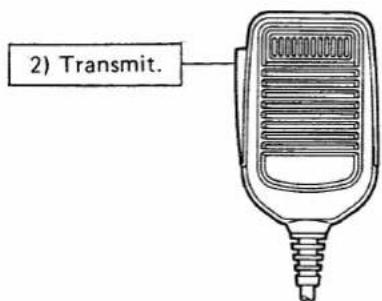
text_image
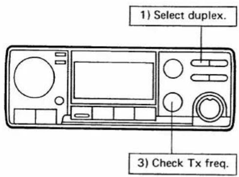
2) Transmit.When working a repeater, set the transceiver to duplex. To access the repeater with a tone, see below.
1) Push [DUP] once for -duplex and again for +duplex.
- "DUP—" or "DUP" appears on the function display.
"DUP—" : Transmit freq. = Receive freq. - Offset freq.
"DUP": Transmit freq. = Receive freq. + Offset freq.
- The VHF and UHF offset frequencies are independently programmed.
2) Push [PTT] to transmit on the repeater input frequency.
- When a tone is required to access the repeater, see below.
3) To check the transmit frequency (repeater input frequency) while receiving, push [SQL/MONITOR].
• The squelch or the tone squelch opens.
- CTCSS SUBAUDIBLE TONE
Push [T/T.SQL] to turn the subaudible tone encoder ON and OFF.
"TONE" appears on the function display.
• 1750 Hz TONE (Europe version)
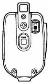
Push and hold the [TONE] switch on the microphone for about 1 \~ 3 seconds to transmit a 1750 Hz tone.
natural_image
Line drawing of a device casing with buttons and mounting holes (no text or symbols)• DTMF TONE (U.S.A. version)
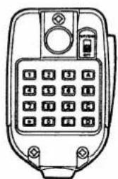
While pushing the [PTT] switch, push the required keys on the microphone.
natural_image
Line drawing of a mobile phone keypad with control buttons and display (no text or symbols)USING SET MODE
SUBAUDIBLE TONE SETTING
text_image
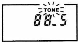
TONE 08:5The display shows that the subaudible tone frequency is 88.5 Hz.
Select one of 38 CTCSS tone frequencies for some repeater operation. When UT-40 is installed, select one of 37 encoder/decoder frequencies.
1) Push [VFO/M] to access the VFO mode.
2) Push [BAND] to select the VHF or UHF.
3) Push [SET] until "TONE" flashes on the function display as shown at left.
4) Rotate the tuning control to select the desired tone frequency.
5) Push [VFO/M] to return to the VFO mode.
USING SET MODE
■ OFFSET FREQUENCY SETTING
text_image
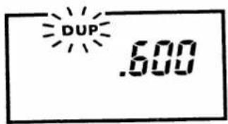
DUP .600The display shows that the offset frequency is 600 kHz (0.6 MHz).
When duplex operation has been selected, the transceiver transmits on a frequency equal to the receive frequency plus or minus the offset frequency.
1) Push [VFO/M] to access the VFO mode.
2) Push [BAND] to select VHF or UHF.
3) Push [SET] until "DUP" flashes on the function display as shown at left.
4) Rotate the tuning control to select the desired offset frequency.
5) Push [VFO/M] to return to the VFO mode.
6 RELATED FUNCTIONS
6-1 FULL DUPLEX
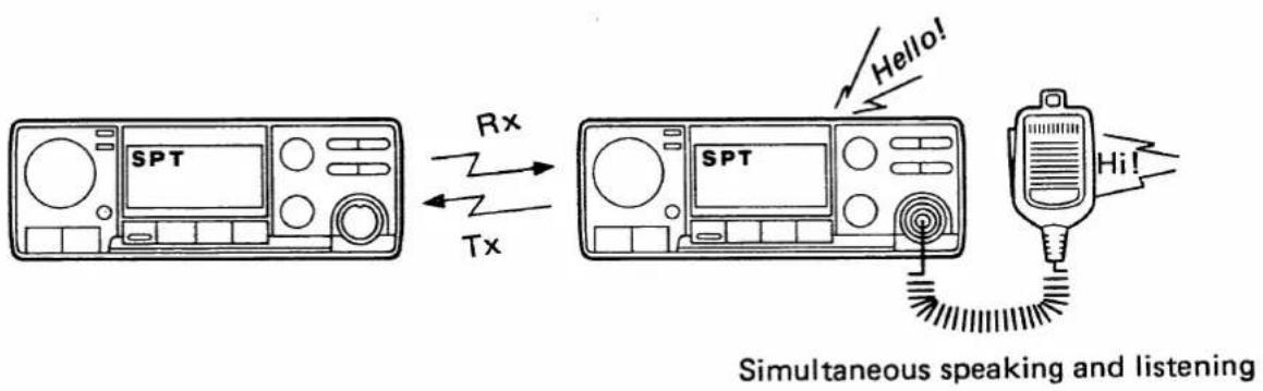
Full duplex operation refers to simultaneous receiving and transmitting.
text_image
SPT Rx Tx SPT Hello! Hi! Simultaneous speaking and listening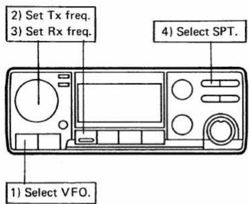
text_image
2) Set Tx freq. 3) Set Rx freq. 4) Select SPT. 1) Select VFO.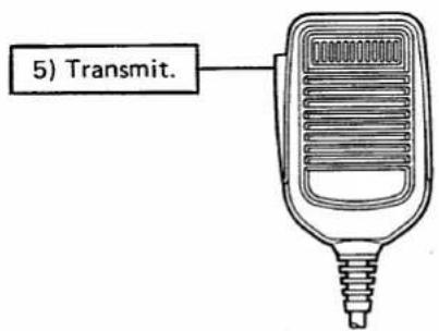
text_image
5) Transmit.1) Push [VFO/M] to access the VFO mode.
2) Set the desired transmit band and frequency.
• See p. 11 for details.
3) Push [BAND] and set the receive frequency.
4) Push [DUP] until "SPT" appears on the function display.
5) Push [PTT] to transmit.
• The transmit frequency is displayed.
- When transmitting, a signal on the receive frequency is heard over the speaker.
6) Both frequencies can be written into one memory channel. Full duplex can be used on a memory channel (p. 19).
NOTE: AVOID setting the UHF frequency near the third multiple of the VHF frequency during full duplex operation. Otherwise the receiver will receive only its own signal.
6-2 CALL CHANNEL MODE
The call channel can be used to store your group frequency or most often used frequency.
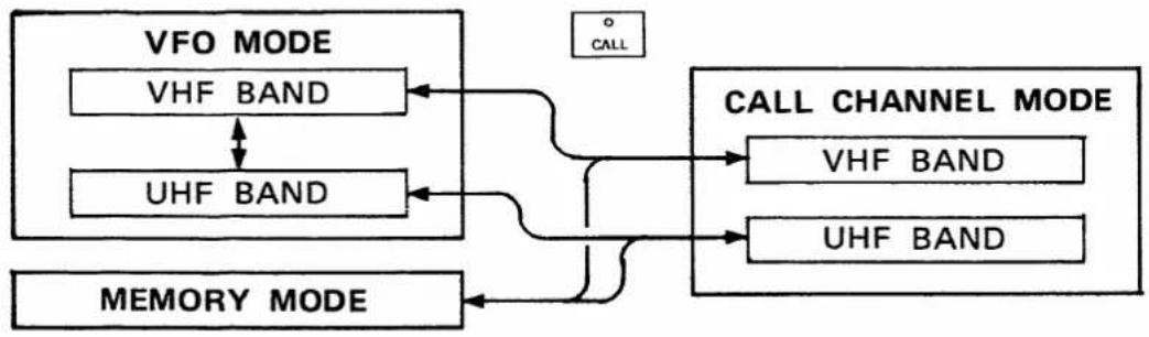
flowchart
graph TD
    A["VFO MODE"] --> B["VHF BAND"]
    A --> C["UHF BAND"]
    D["CALL CHANNEL MODE"] --> E["VHF BAND"]
    D --> F["UHF BAND"]
    G["MEMORY MODE"] --> H["..."]
    I["CALL"] --> A
    J["CALL CHANNEL"] --> D
(1) CALL CHANNEL READING
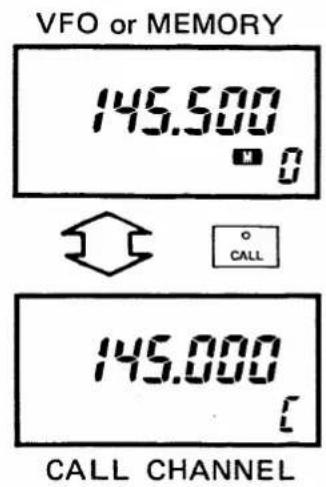
text_image
VFO or MEMORY 145.500 CALL CHANNEL(2) CALL CHANNEL PROGRAMMING
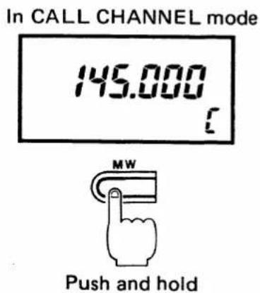
text_image
In CALL CHANNEL mode 145.000 MW Push and hold1) Choose VHF or UHF with [BAND].
2) Push [CALL] to access the call channel.
- "C" appears on the function display.
• The tuning control is deactivated. - Push [CALL] or [VFO/M] to leave the call channel.
1) Push [VFO/M] to access the VFO mode.
2) Choose VHF or UHF with [BAND].
3) Select the contents to be programmed (operating frequency, repeater information, etc.). See pgs. 11, 15.
- The full duplex function can not be programmed into a call channel.
4) Push [CALL] to access the call channel.
5) Push and hold [MW] until three beeps are emitted from the speaker.
6 RELATED FUNCTIONS
6-3 MEMORY MODE
The IC-3210A/E has 20 double-spaced memory channels.
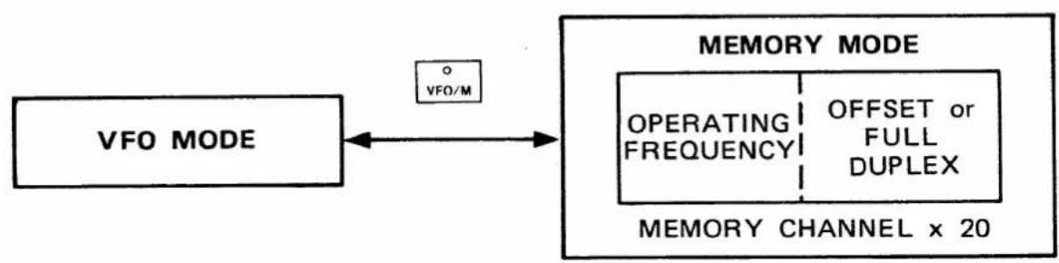
flowchart
graph LR
    A["VFO MODE"] <--> B["MEMORY CHANNEL x 20"]
    B --> C["OPERATING FREQUENCY"]
    C --> D["OFFSET or FULL DUPLEX"]
    D --> E["VFO/M"]
(1) MEMORY READING
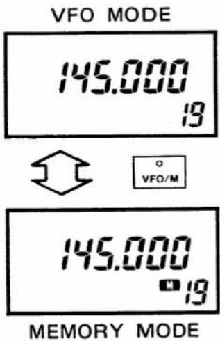
text_image
VFO MODE 145.000 19 VFO/M 145.000 19 MEMORY MODE1) Push [VFO/M] to select the memory mode.
- "M" appears on the function display.
2) Rotate the tuning control or push the [UP] or [DN] switch on the microphone to select a memory channel.
- When full duplex is programmed in a memory channel, push [BAND] for the other operating frequency.
3) Push [VFO/M] to return to the VFO mode.
(2) MEMORY WRITING
text_image
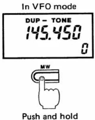
In VFO mode DUP - TONE 145.450 0 MW Push and hold1) Select the memory channel to be programmed (see above).
2) Push [VFO/M] to select the VFO mode.
- "M" disappears from the function display.
3) Select the operating frequency. If desired, repeater or full duplex information contents can be programmed (pgs. 11, 15, 16).
4) Push and hold [MW] until three beeps are emitted from the speaker.
5) The transceiver has written the frequency into the memory channel. To check the contents, push [VFO/M].
(3) DUAL BAND MEMORY
text_image
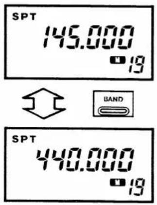
SPT 145.000 19 BAND SPT 440.000 19Each of the 20 memory channels is double-spaced. When a frequency is programmed into each space, you can operate on 40 channels.
1) Program the full duplex function into a memory channel and access that channel. (p. 18)
2) Push [BAND] to select the frequency on the other band.
3) To operate simplex on that frequency, push [DUP] as required.
- The full duplex memory is not erased.
(4) MEMORY TRANSFERRING
text_image
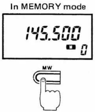
In MEMORY mode 145.500 MWCopy and transfer the displayed memory contents into the VFO mode. This function is useful for searching for signals around the memory channel frequency.
The contents of the memory channel are not erased.
1) Select the memory channel to be transferred. (p. 18)
2) Push and hold [MW] until three beeps are emitted from the speaker.
- The contents of the memory channel have been transferred into the VFO mode.
6 RELATED FUNCTIONS
6-4 SCAN FUNCTION
There are three scan functions: programmed scan, memory scan and selected memory band scan. The memory channel skip function can be used with any memory scan.
(1) PROGRAMMED SCAN
The programmed scan function scans between two frequencies.

flowchart
graph LR
    A["Scan edge A or B"] -->|Scan| B["Scan edge B or A"]
    B -->|Jump| A
PRE-OPERATION
1) Access the VFO mode with [VFO/M].
2) Set the scan edge frequencies as described on p. 21.
3) Rotate [SQL/MONITOR] to the squelch threshold point.
• The [RX] indicator goes out.
OPERATION
text_image
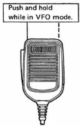
Push and hold while in VFO mode.1) Push and hold [UP] or [DN] on the microphone for about 0.5 seconds to start a programmed scan.
• [UP] : upward scan
[DN] : downward scan
2) When receiving a signal, scanning stops.
• After 15 seconds, scanning resumes.
- 2 seconds after the signal disappears, scanning starts again.
3) To cancel the scan, push [UP] or [DN] on the microphone.
• The tuning control and some other switches also cancel the scan.
USING SET MODE
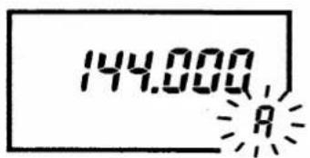
SCAN EDGE SETTING
text_image
144.000 R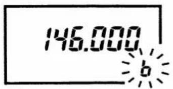
text_image
146.000 b1) Push [VFO/M] to access the VFO mode.
2) Push [BAND] to select VHF or UHF.
3) Push [SET] until "A" flashes on the function display as shown at left.
4) Rotate the tuning control for the desired "A" scan edge frequency.
- Use the [TS] switch together with the tuning control to advance the frequency in 1 MHz steps.
5) Push [SET] once. "b" flashes on the function display.
6) Rotate the tuning control for the desired "b" scan edge frequency.
7) Push [VFO/M] to return to the VFO mode.
6 RELATED FUNCTIONS
(2) MEMORY SCAN
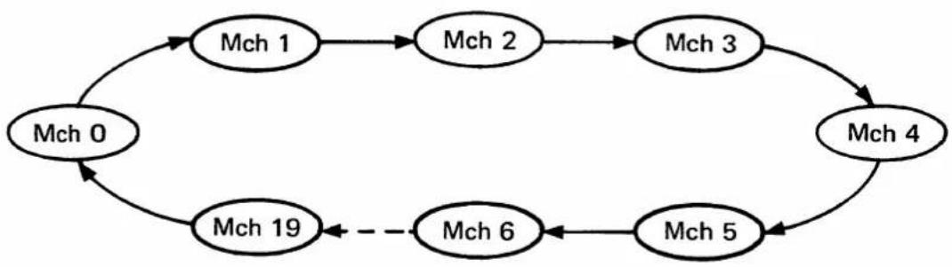
The memory scan function scans all memory channels in succession. To skip certain channels, use the memory channel skip function (p. 24).
flowchart
graph TD
    Mch0 --> Mch1
    Mch1 --> Mch2
    Mch2 --> Mch3
    Mch3 --> Mch4
    Mch4 --> Mch5
    Mch5 --> Mch6
    Mch6 -.-> Mch19
    Mch0 -.-> Mch19
PRE-OPERATION
1) Access the memory mode with [VFO/M].
2) Rotate [SQL/MONITOR] to the squelch threshold point.
• The [RX] indicator goes out.
OPERATION
text_image
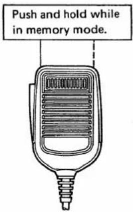
Push and hold while in memory mode.1) Push and hold [UP] or [DN] on the microphone for about 0.5 seconds to start a memory scan.
• [UP] : upward scan [DN] : downward scan
2) When receiving a signal, scanning stops.
• After 15 seconds, scanning resumes.
- 2 seconds after signal disappears, scanning starts again.
3) To cancel the scan, push [UP] or [DN] on the microphone.
- The tuning control, and some other switches also cancel the scan.
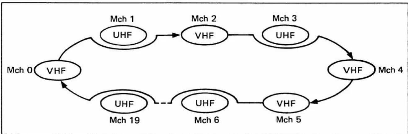
(3) SELECTED BAND MEMORY SCAN
The selected band memory scan function scans all memory channels on one band in succession. To skip certain channels, use the memory channel skip function (p. 24).
flowchart
graph TD
    Mch0["Mch 0"] --> VHF1["VHF"]
    VHF1 --> Mch1["Mch 1"]
    Mch1 --> VHF2["VHF"]
    VHF2 --> Mch2["Mch 2"]
    Mch2 --> UHF1
    UHF1 --> VHF3["VHF"]
    VHF3 --> Mch3["Mch 3"]
    Mch3 --> UHF2
    UHF2 --> VHF4["VHF"]
    VHF4 --> Mch4["Mch 4"]
    Mch4 --> VHF5["VHF"]
    VHF5 --> Mch5["Mch 5"]
    Mch5 --> UHF6["UHF"]
    UHF6 --> Mch6["Mch 6"]
    Mch6 --> VHF6
    Mch6 --> UHF7["UHF"]
    UHF7 --> Mch7["Mch 7"]
    Mch7 --> VHF7
    Mch7 --> UHF8["UHF"]
    UHF8 --> Mch8["Mch 8"]
    Mch8 --> VHF8
    Mch8 --> UHF9["UHF"]
    UHF9 --> Mch9["Mch 9"]
    Mch9 --> VHF9
    Mch9 --> UHF10["UHF"]
    UHF10 --> Mch10
    Mch10 --> VHF10
    Mch10 --> UHF11["UHF"]
    UHF11 --> Mch11
    Mch11 --> VHF11
    Mch11 --> UHF12["UHF"]
    UHF12 --> Mch12
    Mch12 --> VHF12
    Mch12 --> UHF13["UHF"]
    UHF13 --> Mch13
    Mch13 --> VHF13
    Mch13 --> UHF14["UHF"]
    UHF14 --> Mch14
    Mch14 --> VHF14
PRE-OPERATION
1) Access the memory mode with [VFO/M].
2) Rotate [SQL/MONITOR] to the squelch threshold point.
• The [RX] indicator goes out.
OPERATION
text_image
Push and hold while in memory mode.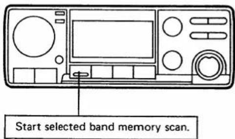
text_image
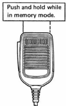
Start selected band memory scan.1) Push and hold [UP] or [DN] on the microphone for about 0.5 seconds to start the scan.
• [UP] : upward scan [DN] : downward scan
2) Push [BAND] to start the selected band memory scan.
- To change the VHF or UHF band, push [BAND] again.
3) When receiving a signal, scanning stops.
- After 15 seconds, scanning resumes. - 2 seconds after signal disappears, scanning starts again.
4) To cancel the scan, push [UP] or [DN] on the microphone.
- The tuning control, [VFO/M] and [CALL] also cancel the scan.
6 RELATED FUNCTIONS
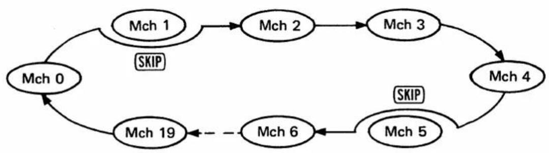
(4) MEMORY CHANNEL SKIP
Program the memory channel skip function to skip a channel during a memory or selected band memory scan.
The memory skip function can also be used for priority watch. See p. 26, VFO ↔ MEMORY CHANNELS.
flowchart
graph TD
    Mch0["Mch 0"] --> Mch1["Mch 1"]
    Mch1 --> Mch2["Mch 2"]
    Mch2 --> Mch3["Mch 3"]
    Mch3 --> Mch4["Mch 4"]
    Mch4 --> Mch5["Mch 5"]
    Mch5 --> Mch6["Mch 6"]
    Mch6 --> Mch19["Mch 19"]
    Mch19 --> Mch0
    Mch2 -->|SKIP| Mch0
    Mch3 -->|SKIP| Mch4
    Mch6 -.-> Mch6
text_image
2) Select a channel. 1) Access memory. 3) Push to program.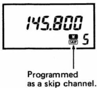
text_image
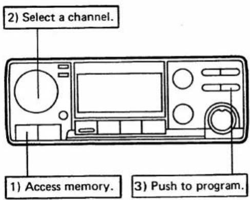
145.800 SKIP 5 Programmed as a skip channel.1) Access the memory mode with [VFO/M].
- "M" appears on the function display.
2) Select the memory channel to be skipped with the tuning control.
3) Push [SET] to program the selected memory channel to be skipped.
- "SKIP" appears on the function display.
4) Push [SET] again to cancel the memory channel skip function for that channel.
- "SKIP" disappears from the function display.
6-5 PRIORITY WATCH
Every five seconds, priority watch monitors a watching frequency while you work on the VFO frequency.
(1) VFO ↔ VFO, MEMORY or CALL CHANNEL

flowchart
graph LR
    A["Operating frequency VFO"] --> B["Watching frequency MEMORY or CALL"]
- Transmitting accepted while watch continues.
- [PRIO] cancels watch.
While receiving on watching frequency:
- Transmitting not accepted.
- [PRIO] returns to operating frequency.
PRE-OPERATION
• VFO frequency watch
1) Set the VFO frequency to be watched.
2) Push [BAND] and set the VFO operating frequency on the other band.
- Call channel watch
1) Set the VFO operating frequency.
2) Push [CALL] to access the call channel.
• Memory channel watch
1) Set the VFO operating frequency.
2) Select the memory channel to be watched (p. 18).
OPERATION
text_image
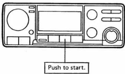
Push to start.1) Push [PRIO] to start priority watch.
- "PRIO" appears on the function display.
2) When a signal is received on the watching frequency (memory, call or another band VFO), priority watch stops for 15 seconds.
• After 15 seconds, priority watch resumes.
3) To cancel priority watch, push [PRIO] when the operating frequency is displayed.
6 RELATED FUNCTIONS
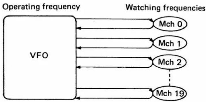
(2) VFO MEMORY CHANNELS
Priority watch can also watch each memory channel in approx. 5 sec. consecutive intervals.
flowchart
graph LR
    A["VFO"] --> B["Mch 0"]
    A --> C["Mch 1"]
    A --> D["Mch 2"]
    A --> E["Mch 19"]
    B --> F["Watching frequencies"]
    C --> F
    D --> F
    E --> F
    F --> G["Operating frequency"]
- Transmitting accepted while watch continues.
- [PRIO] cancels watch.
While receiving on watching frequency:
- Transmitting not accepted.
- [PRIO] returns to operating frequency.
PRE-OPERATION
OPERATION
text_image
1) Start memory scan.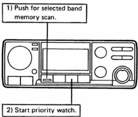
text_image
1) Push for selected band memory scan. 2) Start priority watch.1) Set the VFO operating frequency.
2) Push [VFO/M] to access the memory mode.
3) To skip a channel when scanning, push [SET].
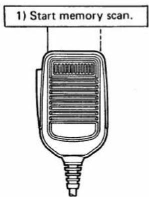
1) Start the memory scan or the selected band memory scan.
- Memory scan
Push and hold [UP] or [DN] on the microphone.
- Selected band memory scan
Start a memory scan, and push [BAND] as required.
2) Push [PRIO] to start priority watch.
- "PRIO" appears on the function display.
• The memory channel changes every five seconds.
3) When a signal is received on the watching frequency (memory channel), priority watch stops for 15 seconds.
• After 15 seconds, priority watch resumes.
4) To cancel priority watch, push [PRIO] when the operating frequency is displayed.
RELATED FUNCTIONS 6
6-6 DIMMER CONTROL
text_image
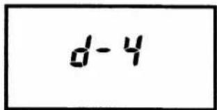
d-4The display for the brightest intensity.
The intensity of the function display backlight is adjustable using the SET mode.
1) Push [VFO/M] to access the VFO mode.
2) Push [SET] until "d-1," "d-2," "d-3" or "d-4" appears on the function display.
3) Rotate the tuning control for the desired lighting intensity.
4) Push [VFO/M] to return to the VFO mode.
6-7 BEEP ON/OFF FUNCTION
text_image
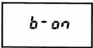
b-onThe display shows that the beep is ON.
The speaker emits a beep each time a switch is pushed. To turn OFF the beeps, use the SET mode.
1) Push [VFO/M] to access the VFO mode.
2) Push [SET] until "b-on" or "b-oFF" appears on the function display.
3) Rotate the tuning control to select "b-oFF."
- To turn ON the beeps again, rotate the tuning control to select "b-on."
4) Push [VFO/M] or [SET] to leave the SET mode.
6-8 LOCK FUNCTION
text_image
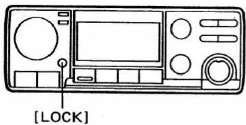
[LOCK]1) To lock switches and controls, push [LOCK].
- "L" appears on the function display.
- [SQL/MONITOR], [ON/VOL] and [PTT] remain unlocked.
2) To unlock the switches and controls, push [LOCK] again.
7 POCKET BEEP AND TONE SQUELCH
7-1 UT-40 INSTALLATION
Install the UT-40 TONE SQUELCH UNIT (sold separately) for "pocket beep" and tone squelch functions.
CAUTION: Turn OFF the power and disconnect the power cord before removing the cover from the transceiver.
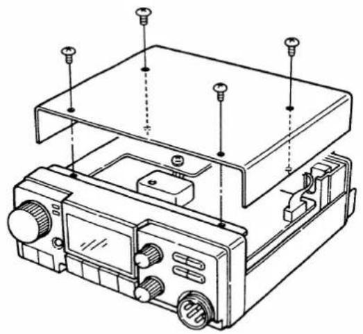
1) Remove four screws from the top cover and remove the cover.
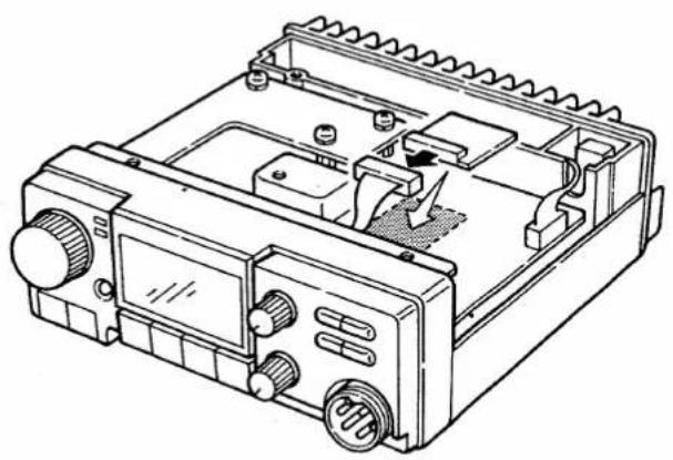
2) Connect the UT-40 to the 10-pin plug as shown in the diagram below.
3) Remove the white sheet from the back of the UT-40. Attach the black adhesive to the IC (S7116A) as shown diagram below.
4) Replace the top cover and the four screws.
- Opening the top cover
natural_image
Technical line drawing of an electronic device with mounting holes and control panel (no text or symbols)• Installing the UT-40
natural_image
Technical line drawing of an electronic device casing with internal components and a directional arrow indicating motion (no text or symbols)POCKET BEEP AND TONE SQUELCH 7
7-2 POCKET BEEP
text_image
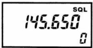
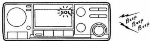
145.650 SQL 0When "pocket beep" is activated, the transceiver functions as a pager. When a received tone frequency equals the tone you've set, an alarm of 30 seconds is emitted over the speaker.
To set a tone frequency, see p. 15. Install the UT-40 (sold separately) for "pocket beep" operation.
text_image
SOL BEEP BEEP BEEP1) Push [T/T.SQL] until "SQL" appears on the function display.
2) When a signal with the correct tone is received, an alarm of 30 seconds is emitted over the speaker and "SQL" flashes.
3) Push any switch to stop the alarm.
- The tone squelch function is automatically activated.
7-3 TONE SQUELCH
text_image
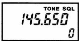
TONE SQL 145.650 0When a received tone frequency equals the tone frequency you've set, the squelch opens.
To set a tone frequency, see p. 15. Install the UT-40 (sold separately) for the tone squelch operation.
text_image
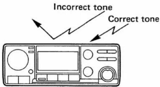
Incorrect tone Correct tone1) Push [T/T.SQL] until "TONE SQL" appears on the function display.
2) When the correct tone frequency is received, the squelch opens and the signal can be heard.
3) Push [SQL/MONITOR] to open the squelch, if desired.
4) When an incorrect tone frequency is received, the squelch does not open. However, the [RX] indicator lights.
8 MAINTENANCE
8-1 TROUBLESHOOTING
| PROBLEM | POSSIBLE CAUSE | SOLUTION | REF. |
| No power. | Power connector has a poor contact.Polarity of the power connection is reversed.Blown fuse. | Check the connector pins.Reconnect the power cable observing the proper polarity.Check the cause, then replace the fuse. | p. 7p. 31 |
| No sound comes from the speaker. | [SQL/MONITOR] is turned too far clockwise.The optional tone squelch is turned ON, if UT-40 is installed. | Set [SQL/MONITOR] at the threshold point.Turn OFF the tone squelch function. | p. 12p. 29 |
| Sensitivity is low and only strong signals are audible. | Antenna feedline or the soldering of antenna connector is cut or short circuited. | Check, and if necessary, replace the feedline or solder the antenna connector again. | p. 8 |
| No contact possible with another station. | The transceiver is set to semi or full duplex.The other station is using the tone squelch. | Set to simplex.Turn ON the tone squelch, if UT-40 is installed. | p. 13p. 29 |
| Repeater can not be accessed. | Wrong offset frequency is programmed.Wrong subaudible tone frequency is programmed. | Correct the offset frequency.Correct the subaudible tone frequency.Be sure the offset and the subaudible tone frequencies are independently programmed on each memory channel. | p. 15p. 15 |
| Frequency can not be set. | The [LOCK] switch is turned ON.CALL CHANNEL mode is selected. | Turn OFF the [LOCK] switch.Push [CALL] to leave CALL CHANNEL mode. | p. 27p. 17 |
| • Scan does not operate. | • Squelch is open.• Scan edge A equals B (for programmed scan).• All memory channels are programmed as the skip channel (for memory scan). | • Set squelch threshold point.• Reset scan edges.• Cancel the memory skip function in the desired channel. | p. 20p. 21p. 24 |
| • All programmed memories have been erased. | • Data error occurred in the CPU RAM because of the following problems.- The backup battery is empty.- The CPU has been damaged by static. | • Replace the backup bat-tery.Reset the CPU. | p. 32p. 32 |
| • SET mode can not be accessed. | • Memory mode is selected. | • Select VFO mode then push [SET]. | p. 10 |
8-2 FUSE REPLACEMENT
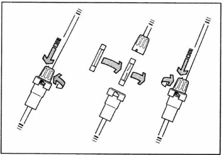
Locate the cause before replacing a blown fuse.
- DC line fuse : 15A
flowchart
graph TD
    A["Component 1"] --> B["Component 2"]
    B --> C["Component 3"]
    C --> D["Component 4"]
8 MAINTENANCE
8-3 CPU RESETTING
NOTE: Resetting the CPU erases all information written into memory channels.
(1) AUTOMATIC RESET
When the power is ON, the CPU is automatically reset under the following conditions:
— The backup battery is empty.
- Static or magnetic field has caused a data error in the CPU RAM.
(2) MANUAL RESETTING
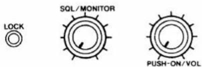
text_image
LOCK SQL/MONITOR PUSH-ON/VOL1) Turn OFF the power.
2) While pushing and holding [SQL/MONITOR] and [LOCK], turn ON the power.
(3) RESETTING THE TUNING STEPS
To exchange 5, 10, 15, 20 or 25kHz tuning steps for 12.5 or 25 kHz steps (and vice-versa), reset the CPU as follows:
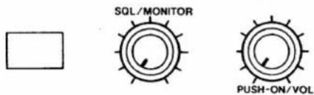
text_image
SQL/MONITOR PUSH-ON/VOL1) Turn OFF the power.
2) While pushing and holding [SQL/MONITOR] and one of the following switches, turn ON the power.
• VHF band 5 kHz → 12.5 kHz : [PRIO]
VHF band 12.5 kHz → 5 kHz : [HI/LO]
UHF band 5 kHz → 12.5 kHz : [BAND]
UHF band 12.5 kHz → 5 kHz : [TS]
(4) BACKUP BATTERY
The life of the lithium backup battery is usually more than five years. When the battery is exhausted, the transceiver operates normally but the CPU does not retain the contents of the memory.
NOTE: DO NOT replace the backup battery yourself. It can be replaced only by an authorized Icom Delaer or Service Center.
TOP VIEW (MAIN AND VHF PA UNITS)
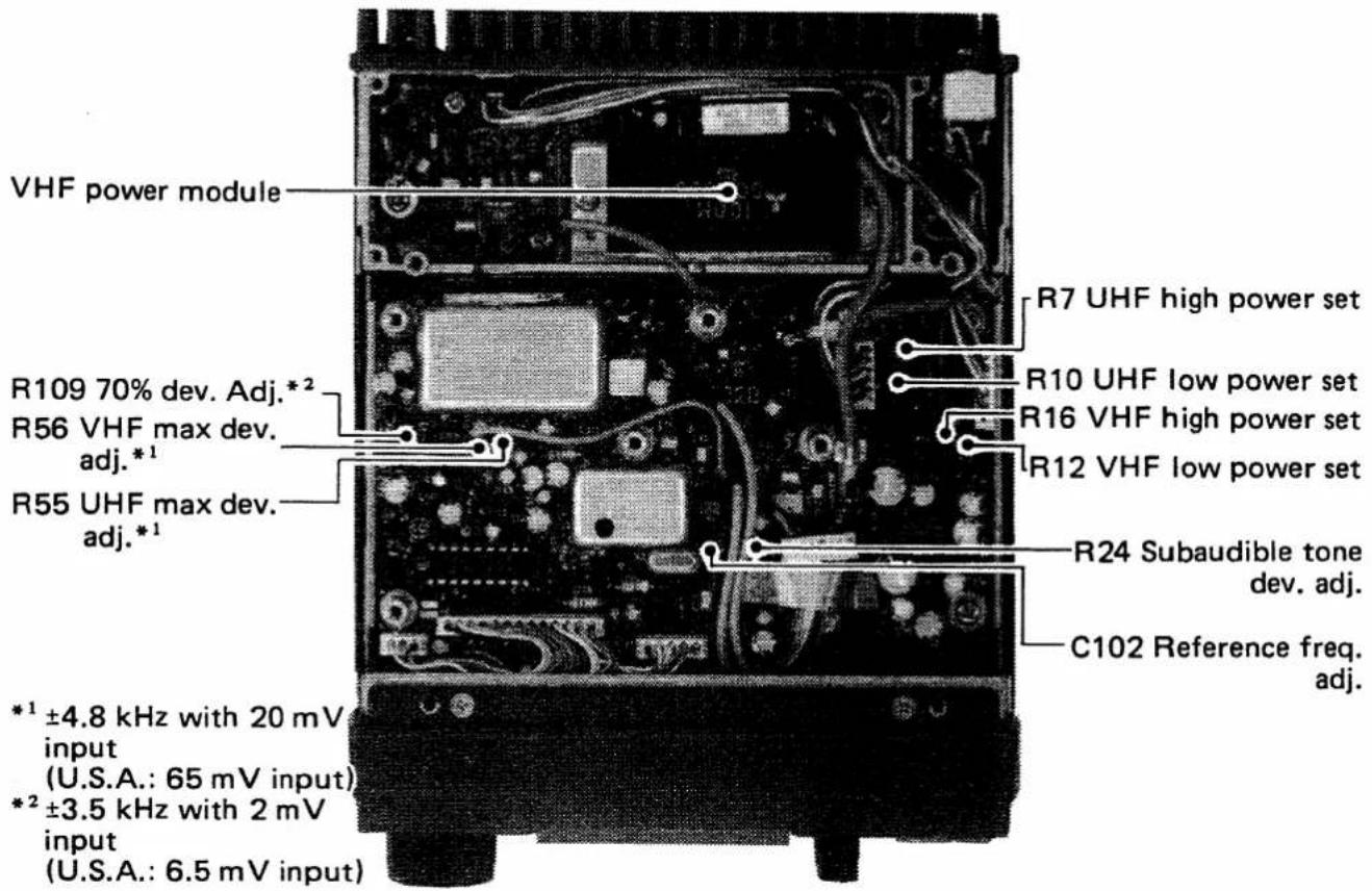
text_image
VHF power module R109 70% dev. Adj.*2 R56 VHF max dev. adj.*1 R55 UHF max dev. adj.*1 *1 ±4.8 kHz with 20 mV input (U.S.A.: 65 mV input) *2 ±3.5 kHz with 2 mV input (U.S.A.: 6.5 mV input) R7 UHF high power set R10 UHF low power set R16 VHF high power set R12 VHF low power set R24 Subaudible tone dev. adj. C102 Reference freq. adj. *1 ±4.8 kHz with 20 mV inputBOTTOM VIEW (RX AND UHF PA UNITS)
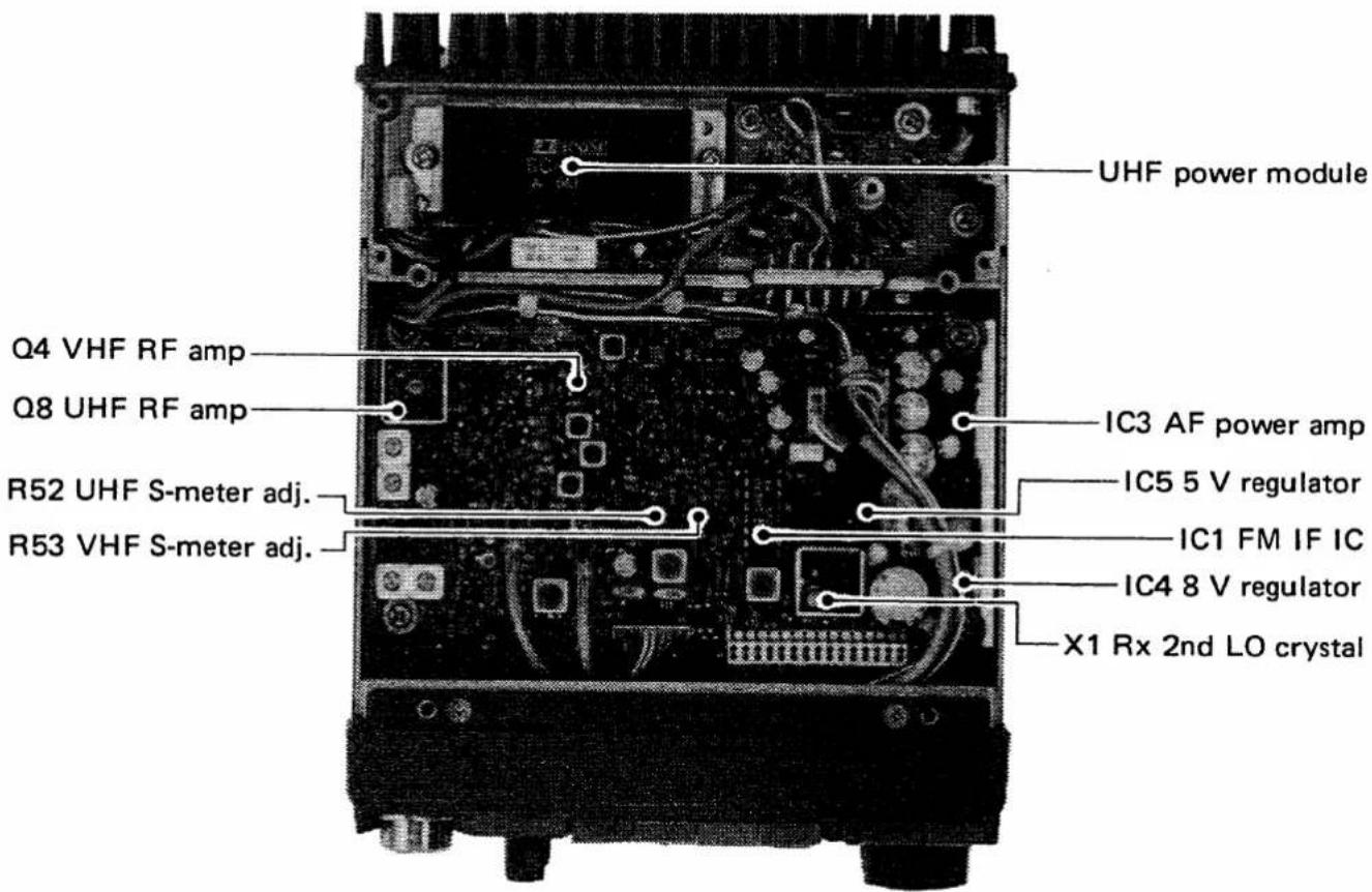
text_image
UHF power module Q4 VHF RF amp Q8 UHF RF amp R52 UHF S-meter adj. R53 VHF S-meter adj. IC3 AF power amp IC5 5 V regulator IC1 FM IF IC IC4 8 V regulator X1 Rx 2nd LO crystal10 SPECIFICATIONS
GENERAL
● Frequency coverage :
| MODEL | VERSION | VHF | UHF |
| IC-3210A | U.S.A. | 138.00 ~ 174.00 MHz* (Rx)140.00 ~ 150.00 MHz* (Tx) | 440.00 ~ 450.00 MHz |
| IC-3210A | Australia | 144.00 ~ 148.00 MHz | 430.00 ~ 440.00 MHz |
| IC-3210E | Europe | 144.00 ~ 146.00 MHz | 430.00 ~ 440.00 MHz |
* Specifications apply to only 144.00 \~ 148.00 MHz.
- Mode : F3 (FM)
- Selectable tuning step : 5, 10, 15, 20 and 25 kHz (IC-3210A)
12.5 and 25 kHz (IC-3210E)
● Memory channels : 20 (double-spaced) memory channels plus two call channels
- Antenna impedance : 50 Ω
● Power supply requirement : 13.8 V DC ± 15 % (negative ground)
- Current drain : Receive standby 550 mA
max. audio 900 mA (except full duplex operation)
Transmit high 7.6 A
low 3.6 A
- Usable temperature range : -10^ +60^ (+14°F \~ +140°F)
- Frequency stability : ± 10 ppm (-10°C \~ +60°C)
- Dimensions : 140 (W) × 50 (H) × 180 (D) mm
5.5 (W) × 2.0 (H) × 7.1 (D) inches
(Projections not included)
● Weight : 1.2 kg (2.6 lbs.)
TRANSMITTER
- Output power : 25 W (high), 5 W (low)
- Modulation system : Variable reactance frequency modulation
● Max. frequency deviation : ± 5 kHz
- Spurious emissions : Less than -60 dB
● Microphone impedance : 600 Ω
RECEIVER
- Receiver system : Double-conversion superheterodyne
- Intermediate frequency : 1st 30.875 MHz
2nd 455 kHz
- Sensitivity : 0.18 μV for 12 dB SINAD
- Selectivity : More than 12.5 kHz/—6 dB
Less than 30.0 kHz/—60 dB
- Audio output power : More than 2.4 W at 10 % distortion with an 8 Ω load.
• Audio output impedance : 8 Ω
All stated specifications are subject to change without notice or obligation.
natural_image
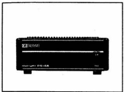
Front view of a black industrial device labeled 'Z-1COX' with no visible text or symbols on its body.PS-45
AC POWER SUPPLY
13.8 V 8 A
An OPC-102 cable must be purchased separately to connect the IC-3210A/E to the PS-45.
natural_image
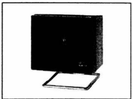
Black-and-white illustration of a desktop computer monitor with a stand (no text or symbols visible)SP-7
EXTERNAL SPEAKER
natural_image
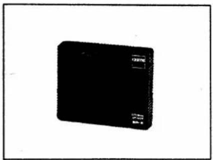
Black rectangular electronic device with a small label on its side (no visible text or symbols on the device itself)SP-8
EXTERNAL SPEAKER
natural_image
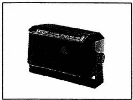
Black rectangular electronic device with a label, no visible text or symbols on the bodySP-10
EXTERNAL SPEAKER
natural_image
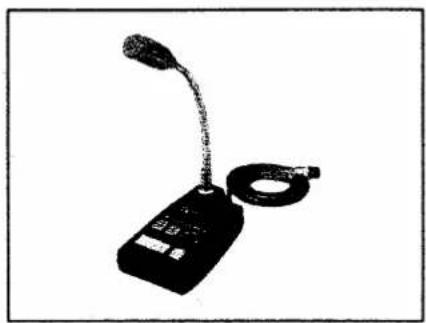
Black-and-white photo of a handheld electronic device with a curved neck and coiled cable (no visible text or symbols)SM-8
DESK MICROPHONE
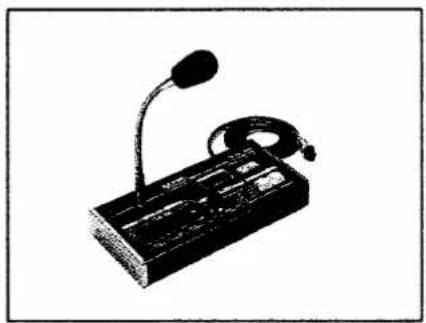
natural_image
Black-and-white illustration of a desktop computer with a microphone and ear (no text or symbols)SM-10
COMPRESSOR/GRAPHIC
EQUALIZER DESK TOP
MICROPHONE
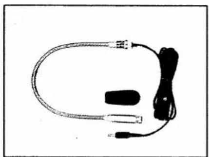
natural_image
Coiled medical device with connectors and a small black connector (no visible text or symbols)HS-15
FLEXIBLE MOBILE
MICROPHONE
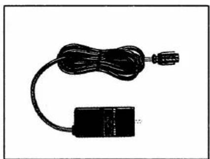
natural_image
Simple black electrical circuit breaker with coiled cable and terminal connector (no text or symbols)HS-15SB
SWITCHBOX FOR
HS-15
natural_image
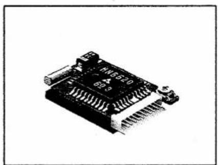
Close-up of an electronic component with visible pins and connectors (no text or symbols)UT-40
TONE SQUELCH UNIT
| AH-32 | 144/430 MHz DUAL BAND MOBILE ANTENNA |
| AHB-32 | TRUNK MOUNT |
Count on us!