
IC-471H - Empfänger ICOM - Kostenlose Bedienungsanleitung
Finden Sie kostenlos die Bedienungsanleitung des Geräts IC-471H ICOM als PDF.


Benutzerfragen zu IC-471H ICOM
0 Frage zu diesem Gerät. Beantworten Sie die, die Sie kennen, oder stellen Sie Ihre eigene.
Eine neue Frage zu diesem Gerät stellen
Laden Sie die Anleitung für Ihr Empfänger kostenlos im PDF-Format! Finden Sie Ihr Handbuch IC-471H - ICOM und nehmen Sie Ihr elektronisches Gerät wieder in die Hand. Auf dieser Seite sind alle Dokumente veröffentlicht, die für die Verwendung Ihres Geräts notwendig sind. IC-471H von der Marke ICOM.
BEDIENUNGSANLEITUNG IC-471H ICOM
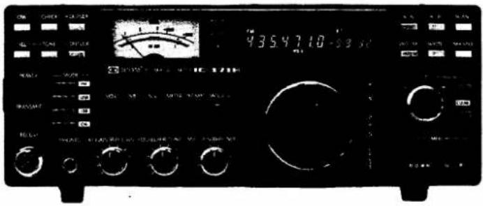
IC-471H
430MHz ALL MODE TRANSEIVER
INSTRUCTION MANUAL
text_image
ON CHECK +0.025 4354710-59.10 RANGE RANGE RANGE RANGE RANGE RANGE RANGE RANGE RANGE RANGE RANGE RANGE RANGE RANGE RANGE RANGE RANGE RANGE RANGE RANGE RANGE RANGE RANGE RANGE RANGE RANGE RANGE RANGE RANGE RANGE RANGE RANGE RANGE RANGETABLE OF CONTENTS
SECTION 1 SPECIFICATIONS.... 1
SECTION 2 FEATURES 2
SECTION 3 INSTALLATION 3
SECTION 4 OPERATING CONTROLS....5
4-1 FRONT PANEL 5
4-2 CONTROLS UNDER THE ACCESS COVER....7
4-3 REAR PANEL CONNECTIONS.... 8
SECTION 5 OPERATING INSTRUCTIONS....9
5-1 HOW TO TUNE 9
5-2 MEMORY CHANNEL OPERATION 14
5-3 TUNING BY UP/DOWN BUTTON ON THE MICROPHONE....15
5-4 SCANNING OPERATION....16
5-5 SSB OPERATION 17
5-6 CW OPERATION....18
5-7 FM OPERATION....19
SECTION 6 INSIDE VIEWS....20
SECTION 7 OPTION INSTALLATION....22
SECTION 8 TROUBLESHOOTING....25
SECTION 9 VOLTAGE CHARTS....26
SECTION 10 BLOCK DIAGRAM....29
SECTION 11 SCHEMATIC DIAGRAM....SEPARATE
SECTION 1 SPECIFICATIONS
GENERAL
Number of Semiconductors:
| Transistors | 126 (European version: 133) |
| (Australian version: 135) |
FET 14
| IC (Includes CPU) | 60 (European version: 57)(Australian version: 59) |
Diodes 196 (European version: 190)
Frequency Coverage:
430MHz \~ 450MHz
(European version 430MHz \~ 440MHz)
Frequency Control:
CPU based 10Hz step PLL synthesizer.
Independent Transmit-Receive Frequency Capability 32
Memory Channels provided
Programmed Scan, Memory Channel Scan and Mode-Selective Scan Capability
Frequency Resolution:
SSB 10Hz steps (Automatic 100Hz steps shift)
FM 5KHz steps
1KHz steps with TUNING RATE switch depressed
Frequency Readout:
7 digit Luminescent display 100Hz readout
Frequency Stability:
Within ±0.001% in the range of -10°C \~ +60°C
RIT Frequency Coverage:
±9.9KHz from displayed receive frequency
Power Supply Requirements:
| DC 13.8V ±15% Negative ground Current drain 20A max. AC power supply is available for AC operation. |
Current Drain (at 13.8V DC):
Transmitting 75 watts output Approx. 19.0A
10 watts output Approx. 8.0A
Receiving At max. audio output 1.4A
Squelched 1.2A
Antenna Impedance:
50 ohms Unbalanced
Weight:
7.1 Kg
Dimensions:
110(125)mm(H) × 285(300)mm(W) × 275(324)mm(D)
( ): Shows the dimensions including projections
TRANSMITTER
RF Output Power:
SSB (A _3 J) 75 Watts PEP
CW (A 1 ), FM (F 3 ) 75 Watts
Continuously Adjustable Output power 10 watts \~ Max.
Emission Mode:
SSB (A3J USB/LSB), CW (A1), FM (F3)
Modulation System:
SSB: Balanced modulation
FM: Variable reactance frequency modulation
Max. Frequency Deviation:
±5KHz
Harmonic Output:
More than 60dB below peak power output
Spurious Output:
More than 60dB below peak power output
Carrier Suppression:
More than 40dB below peak power output
Unwanted Sideband:
More than 40dB down at 1000Hz AF input
Microphone:
600 ohm electret condenser microphone with push-to-talk switch and scanning buttons.
Operating Mode:
Simplex, Duplex (Any in-band 10KHz steps frequency separation programmable)
RECEIVER
Receiving System:
SSB, CW Double conversion superheterodyne
FM Triple conversion superheterodyne
Receiving Mode:
A_1, A_3J (USB, LSB), F_3
IF Frequencies:
SSB, CW 70.4515MHz, 10.75MHz
FM 70.4515MHz, 10.75MHz, 455KHz
Sensitivity:
SSB, CW Less than 0.3 microvolts for 10dB S+N/N
FM Less than 0.3 microvolts for 12dB SINAD
Less than 0.5 microvolts for 20dB noise quieting
Squelch Sensitivity:
SSB, CW Less than 1 microvolt
FM Less than 0.3 microvolts
Spurious response rejection ratio:
More than 60dB
Selectivity:
SSB, CW More than 2.4KHz at -6dB point
Less than 4.8KHz at -60dB point
FM More than 15KHz at -6dB point
Less than 30KHz at -60dB point
Audio Output Power:
More than 2.0 watts (at 8 ohm 10% distortion)
Audio Output Impedance:
8 ohms
Specifications are approximate and are subject to change without notice or obligation.
430MHz ALL-MODE 75 WATTS TRANSCEIVER INCORPORATING A MICROCOMPUTER
CPU control with ICOM's original programs provides various operating capabilities. A no-backlash dial controls by ICOM's unique rotary encoder circuit. The Band-edge detector and the Endless System provides out-of-band protection. Variable capacitors and dial gear are not utilized and therefore provide problem-free use. The IC-471H provides FM, USB, LSB, CW coverage in the 430 \~ 450MHz (European version: 430 \~ 440MHz) frequency range with 75 watts output power. Thus the IC-471H can be used for mobile, DX, local calls, and satellite work.
MULTI-PURPOSE SCANNING
Memory Scan allows you to monitor all different memory channels or only those stored with a particular mode. Program Scan provides scanning between two programmed frequencies. Auto-stop scanning when a signal is received, in any mode.
DUAL VFO'S AND 32 MEMORY CHANNELS
Two separate VFO's can be used either independently or together for simplex operation, and any desired frequency split in duplex operation.
The IC-471H has 32 memory channels and each channel stores the operating frequency as well as the mode, duplex/simplex and subaudible tone frequency (U.S.A. version only).
CONTINUOUS TUNING SYSTEM
ICOM's new continuous tuning system features a luminescent display that follows the tuning knob movement and provides an extremely accurate readout. Frequencies are displayed in 7 digits representing 100MHz to 100Hz digits.
Automatic recycling restarts tuning at the top of the band, i.e., the high edge when the dial goes below the low edge. Recycling changes the high edge to the low edge as well. Quick tuning in 1KHz steps is available, and fine tuning in 10Hz steps in the SSB and CW modes, and 5KHz steps and 1KHz steps in the FM mode, is provided for trouble-free QSO.
EASY-TO-READ DISPLAY
The IC-471H employs an easy-to-read large luminescent display. This displays the operating frequency as well as the VFO in use, operating mode, RIT shift frequency, duplex mode, scan mode, etc.
EASIER OPERATION, LIGHTER WEIGHT AND HIGHER POWER
The IC-471H is the most compact 75 watt, lightest weight all-mode 430MHz transceiver. It is the first to use a pulse power supply (option) in communication equipment, for light weight. A 50mm-diameter large tuning control knob is provided for smooth and easy tuning. Easy to use control knobs are provided for both receiving and transmitting. An LED indicates the transmit or receive mode.
MOST SUITABLE FOR BOTH FIXED AND PORTABLE STATIONS
The transceiver can be operated with a self-contained 117/240V AC (option) or 12V DC power supplies. A convenient Dial Lock switch is included for mobile operation as well as an easy-carry handle. An effective Noise Blanker reduces pulse noise. The IC-SM6, high quality stand microphone (option), is suitable for fixed station operation. A powerful audio output, 2.0 watts at 8 ohm, provides easy listening even in noisy surroundings.
OUTSTANDING PERFORMANCE
The RF amplifier and the first mixer circuit incorporate FET's, and other circuits provide excellent Cross Modulation and Two-Signal Selectivity characteristics. The IC-471H has excellent sensitivity, demanded especially for mobile operation, high stability, and utilizes Crystal Filters having high shape factors and exceptional selectivity.
The transmitter uses a balanced mixer in a double conversion system, a band-pass filter and a high-performance low-pass filter. This system provides distortion-free signals with a minimum spurious radiation level.
BE SURE TO READ THE FOLLOWING INSTRUCTIONS CAREFULLY BEFORE OPERATION
3-1 UNPACKING
Carefully remove your transceiver from the packing carton and examine it for signs of shipping damage. Should any be apparent, notify the delivering carrier or dealer immediately, stating the full extent of the damage. It is recommended you to keep the shipping cartons. In the event storage, moving, or reshipment becomes necessary they will be handy. Accessory cables, plugs, etc., are packed with the transceiver. Make sure you have not overlooked anything.
- Microphone (IC-HM12) 1
- DC Power Cord.... 1
- External Speaker Plug 1
- Key Plug 1
- Spare Fuses (20 Amp) 2
- Wiring Fastener. 3
3 - 2 RECOMMENDATIONS FOR INSTALLATION
- Avoid placing the IC-471H in direct sunlight, high temperature, dusty or humid places.
- The temperature of the set will usually become relatively warm during transmission. Any equipment should be at least 1 inch (3cm) away from the unit so as to provide good ventilation. Be sure that nothing is on or just behind the rear PA heatsink to ensure good ventilation. Also avoid places near outlets of heaters, air conditioners, etc.
- Place the unit so that the controls and switches can easily be handled and the frequency display and meter can easily be read.
- For mobile installation, an optional mounting bracket is available. Select the best location that can stand the weight of the unit and that does not interfere with your driving in any way.
- Use the Ground Lug!
3-3 POWER SUPPLY
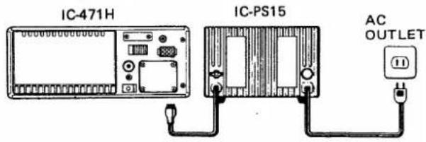
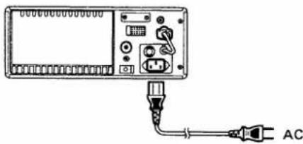
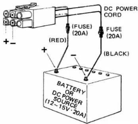
For AC operation, use the special power supply IC-PS15, IC-PS30, or optional built-in power supply IC-PS35. If you would like to use your car battery or any other DC power supply, be sure that its output voltage is 12-15 Volts and the current capacity is at least 20 Amps. The maximum power consumption of the set during transmission runs about 20 Amps, so keep that in mind if the unit is installed in your automobile, and turn it on after you have started the engine. Attention should also be paid to the condition of the battery and electrical system.
The connection of the DC power cord supplied with the IC-471H is done in the following way: First make sure that the power switch of the unit is in the OFF position and the T/R switch is in the receive position. Connect the cord to a DC power supply with the RED lead to the positive terminal and the BLACK lead to the negative terminal. (Reverse connection will cause the protection circuit to operate and blow the fuse.) Connect the DC plug to the socket on the rear panel of the IC-471H. Refer to the drawing below.
For AC operation (with IC-PS15)
text_image
IC-471H IC-PS15 AC OUTLETFor AC operation (when optional IC-PS35 is installed).
natural_image
Diagram of an electronic device with AC power cable and connector, no text or symbols presentFor DC operation
text_image
DC POWER CORD (FUSE) (20A) FUSE (20A) (BLACK) (RED) + - BATTERY OR DC POWER SOURCE (12~15V·20A)3 - 4 ANTENNA
The single most important item that will influence the performance of any communication system is the antenna. For that reason, a good, high-quality, gain antenna of 50 ohms impedance is recommended, for fixed or mobile. In UHF as well as the low bands, every watt of ERP makes some difference. Therefore, 75 watts average output plus 3dB of gain antenna equals 150 watts ERP, presuming low VSWR of course. The few extra dollars invested in a gain type antenna is well worth it. When adjusting your antenna, whether mobile or fixed, by all means follow the manufacturer's instructions.
There are however some pitfalls to be aware of. For example, do not attempt to adjust an antenna for lowest VSWR when using a diode VSWR meter not engineered for UHF applications. Such readings will invariably have an
error of 40% or more. Instead, use an in-line watt meter similar to the Bird model 43 or Sierra model 164B with UHF cartridge. Further, when adjusting a mobile antenna, do so with the engine running preferably above normal idling speed. This will insure proper voltage level to the transceiver.
As the output is quite high, avoid connecting the antenna connector to open lines and do not transmit under mismatched conditions. If SWR is high (more than 3), the output power is reduced to prevent damage to the final transistors.
The RF coaxial connector on the rear chassis mates with a standard N-type (UG-21/U) connector.
3 - 5 MICROPHONE
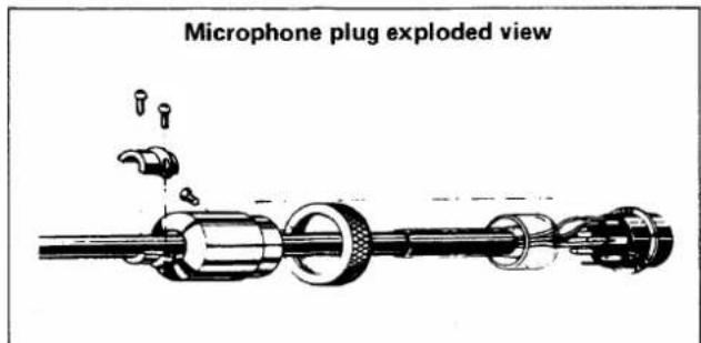
A high quality electret condenser microphone is supplied with your transceiver. Merely plug it into the proper receptacle on the front panel. Should you wish to use a different microphone, make certain it has proper output level. Particular care should be exercised in wiring also, as the internal electrical switching system is dependent upon it. See the schematic for the proper hookup.
text_image
Microphone plug exploded view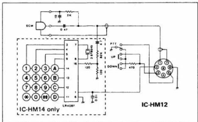
text_image
SCM 2K 0 47 IC-HM14 only LR4087 3 7 4 5 9 8 16 120 BZK 120 PTT UP DOWN 470 IC-HM123-6 CW KEY
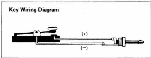
When operating CW, connect a key to the Key Jack with the plug supplied. The connection of the plug is shown below.
If using an electronic keyer, observe proper polarity when installing the key plug. Make sure that the key down voltage across the plug is less than 0.4V DC or improper operation will result.
text_image
Key Wiring Diagram (+) (-)3-7 EXTERNAL SPEAKER
The IC-471H contains an internal speaker, and is also designed so that it can drive an external speaker from the external (EXT) speaker jack on the rear panel. Be sure the impedance of the external speaker is 8 ohms, and remember that with the external speaker connected, the internal speaker is disabled.
3 - 8 HEADPHONES
Any good headphone set, including stereo type, that have 4-16 ohms impedance can be used. With the plug inserted halfway into the PHONES jack, both the headphone and speaker will operate. This is convenient when others wish to listen in on the station, or you wish to record contacts using a tape recorder connected to the headphone jack. With a stereo headphone set inserted this way, however, the headphone will lose the sound on one side. With the plug inserted completely, only the headphone works.
3-9 GROUND
In order to prevent electrical shocks, TVI, BCI and other problems, be sure to connect a heavy wire ground, as short as possible, from a good earth point to the ground terminal on the rear panel.
3 - 10 COOLING FAN
The rear of the PA unit is designed to provide for adequate cooling, but with 200 Watts input the final stage produces quite a bit of heat, and its temperature may rise during prolonged transmissions. The fan is connected to a temperature monitoring circuit which monitors the temperature of the final stage. The fan operates as follows:
- The fan speed is slow in the receive mode and moderate in the transmit mode.
- When the temperature rises to a point (50°C) detected by the temperature monitoring circuit, the fan speed will increase during both transmit and receive modes to provide additional cooling.
- If the temperature rises to a danger limit (90°C) the fan will run much more rapidly. At this time the output power is reduced to a half of the maximum power (about 30 watts) and the RECEIVE INDICATOR will be blinked for a warning until the temperature goes under 90°C. Investigate the cause of overheating i.e. antenna mismatching, etc. and correct the cause of the overheating before starting to transmit again.
4 - 1 FRONT PANEL
text_image
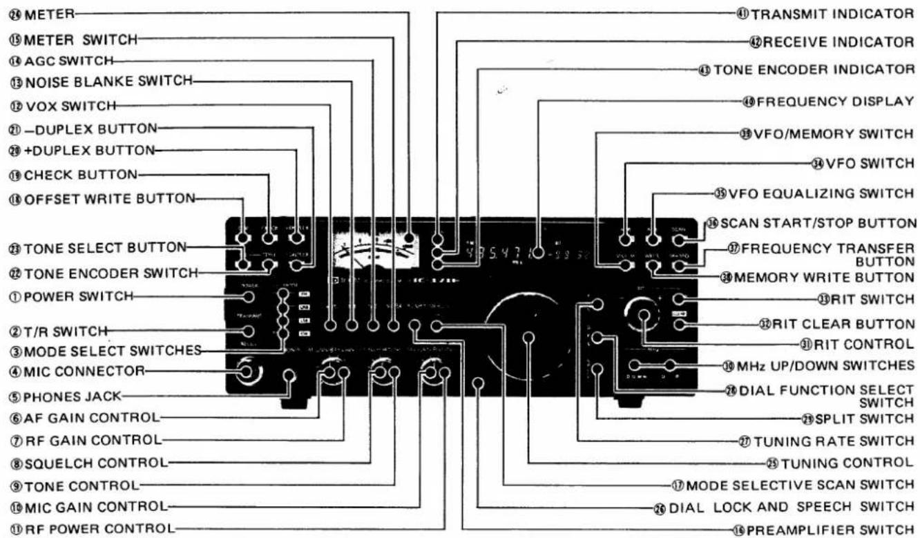
① METER ② METER SWITCH ③ AGC SWITCH ④ NOISE BLANKE SWITCH ⑤ VOX SWITCH ⑥ -DUPLEX BUTTON ⑦ +DUPLEX BUTTON ⑧ CHECK BUTTON ⑨ OFFSET WRITE BUTTON ⑩ TONE SELECT BUTTON ⑪ TONE ENCODER SWITCH ⑫ POWER SWITCH ⑬ T/R SWITCH ⑭ MODE SELECT SWITCHES ⑮ MIC CONNECTOR ⑯ PHONES JACK ⑰ AF GAIN CONTROL ⑱ RF GAIN CONTROL ⑲ SQUELCH CONTROL ⑳ TONE CONTROL ⑴ MIC GAIN CONTROL ⑵ RF POWER CONTROL ⑶ TRANSMIT INDICATOR ⑦ RECEIVE INDICATOR ⑧ TONE ENCODER INDICATOR ⑨ FREQUENCY DISPLAY ⑩ VFO/MEMORY SWITCH ⑪ VFO SWITCH ⑫ VFO EQUALIZING SWITCH ⑬ SCAN START/STOP BUTTON ⑭ FREQUENCY TRANSFER BUTTON ⑮ MEMORY WRITE BUTTON ⑯ RIT SWITCH ⑰ RIT CLEAR BUTTON ⑱ RIT CONTROL ⑲ MHz UP/DOWN SWITCHES ⑳ DIAL FUNCTION SELECT SWITCH ㉑ SPLIT SWITCH ㉒ TUNING RATE SWITCH ㉓ TUNING CONTROL ㉔ MODE SELECTIVE SCAN SWITCH ㉕ DIAL LOCK AND SPEECH SWITCH ㉖ PREAMPLIFIER SWITCH1. POWER SWITCH
The POWER SWITCH is a push-lock type switch which controls the input DC power to the IC-471H. When the external AC power supply (IC-PS15 or IC-PS30) or optional built-in AC power supply (IC-PS35) is used, the switch also acts as the AC power supply switch. When the switch is pushed in and locked, power is supplied to the set. When the switch is pushed again and released, power is cut to all circuits except the PA unit.
2. T/R (TRANSMIT/RECEIVE) SWITCH
This switch is for manually switching from transmit to receive and vice versa. Set the switch to RECEIVE (down) and the IC-471H is in the receive mode. Set the switch to TRANSMIT (up) and it switches to transmit. When switching with the PTT switch on the microphone or with the VOX switch set to ON, the T/R switch must be in the RECEIVE position.
3. MODE SELECT SWITCHES
Selects any one of four operating modes of FM, USB, LSB and CW, by simply pushing the desired switch.
4. MIC CONNECTOR
Connect the supplied microphone or optional microphone to this connector. If you wish to use a different microphone, refer to the drawings on page 4.
5. PHONES JACK
Accepts a standard 1/4 inch headphone plug for headphones of 4 \~ 16 ohms. Stereo phones can be used without modification.
6. AF GAIN CONTROL
Controls the audio output level in the receive mode. Clockwise rotation increases the level.
7. RF GAIN CONTROL
Controls the gain of the RF section in the receiver. Clockwise rotation gives the maximum gain. As the control is rotated counterclockwise, the needle of the METER rises, and only signals stronger than the level indicated by the needle will be heard.
8. SQUELCH CONTROL
Sets the squelch threshold level. To turn OFF the squelch function, rotate this control completely counterclockwise. To set the threshold level higher, rotate the control clockwise.
9. TONE CONTROL
Controls the receiver audio tone. Adjust the control to provide comfortable reception.
10. MIC GAIN CONTROL
Adjusts the level of modulation according to the input of the microphone. As the input will vary with different microphones and different voices, adjust for proper modulation accordingly. Clockwise rotation increases mic gain.
11. RF POWER CONTROL
The IC-471H has an output power of 10\~75 watts which can be varied by the RF POWER control. Turning the control clockwise increases the power, while turning counterclockwise decreases it.
12. VOX SWITCH
This switches the VOX circuit ON and OFF. When it is in the ON (in) position, in SSB, T/R switching is accomplished by means of a voice signal. In CW operation, semi-break-in switching by means of keying is possible.
13. NB (NOISE BLANKER) SWITCH
When pulse type noise such as automobile ignition noise is present, push this switch. The noise will be reduced to provide comfortable reception.
To turn off the noise blanker, push this switch again and release it.
14. AGC (AUTOMATIC GAIN CONTROL) SWITCH
With this switch you can select the time constant of the AGC circuit. With the switch in the out position, the AGC voltage is released slowly, and is suitable for SSB reception. With switch in the locked in position, the AGC voltage is released faster, and the AGC is suitable for stations suffering from fast fading or when operating in the CW mode.
15. METER SWITCH
When this switch is pushed in the FM receive mode, the meter functions as a discriminator meter.
16. PREAMPLIFIER SWITCH
When the optional mast-mounting preamplifier, AG-35, is installed, this switch turns the preamplifier ON/OFF.
17. MODE SELECTIVE SCAN SWITCH
When this switch is pushed, only memory channels stored with the operating mode which is displayed on the frequency display just prior to pushing this switch, are selected by turning the tuning control or scanning.
18. OFFSET WRITE BUTTON
By pushing this button, the offset frequency is displayed on the frequency display. In the FM mode, while this button is depressed, the offset can be reset with 10KHz steps by turning the tuning control.
19. CHECK BUTTON
Depressing this button allows reception on the programmed "TX" frequency and causes the TX frequency to be displayed as long as the button is depressed.
20. +DUPLEX BUTTON
Pushing this button places, the set in the duplex mode with the transmit frequency set 5.0MHz (European version 7.6MHz) (This can be changed to any 10KHz steps in-band frequency.) above the displayed receive frequency. To turn off duplex, push this button again.
21. -DUPLEX BUTTON
Pushing this button places, the set in the duplex mode with the transmit frequency set 5.0MHz (European version 7.6MHz) (This can be changed in 10KHz steps.) below the displayed receive frequency. To turn off duplex, push this button again.
22. TONE ENCODER SWITCH
U.S.A. version: Turns ON/OFF the built-in subaudible tone encoder or the optional encoder/decoder.
European version: Puts the set in the transmit mode and actuates the tone-burst generator.
23. TONE SELECT BUTTON
Selects the frequency of the subaudible tone encoder/decoder. While this button is depressed, a code number is displayed on the frequency display, and this number can be changed by turning the tuning control. (U.S.A. version only)
24. METER
Functions as a relative RF output meter in the transmit mode, and as an S-meter (signal strength meter) in the receive mode. When the meter switch is pushed in, the meter functions as a discriminator meter in the FM receive mode.
25. TUNING CONTROL
Rotating this control clockwise increases the frequency or the memory channel number, while rotating it counterclockwise decreases it. The frequency changes by 10Hz in SSB and CW modes, and 5KHz in FM mode. In the 10Hz step tuning rate, by turning the tuning control faster, the 100Hz step tuning rate is automatically selected. This makes it very convenient to make a QSY over a wide frequency range.
This control is also used to reset the offset frequency and to select the subaudible tone frequency.
26. DIAL LOCK AND SPEECH SWITCH
After the IC-471H is set to a certain frequency for rag chewing, mobile operation, etc., by pushing this switch, the VFO is electronically locked at the displayed frequency, thus inactivating the operation of the tuning control. To change frequency, the dial lock must first be disengaged by pushing and releasing this switch again.
In addition, this switch functions as a switch to turn on the optional speech synthesizer which announces the displayed frequency in English.
27. TUNING RATE SWITCH
By pushing in this switch, the operating frequency is changed to correspond to 1KHz increments in any mode.
At the same time, the 100Hz digit on the display is cleared to show "0". When this switch is pushed again and released, the frequency is changed normally. This switch allows you to quickly QSY over a great frequency range in SSB and CW, and to tune in FM signals which are off from 5KHz-step frequencies.
28. DIAL FUNCTION SELECT SWITCH
In the VFO operation, by pushing in this switch, the operating frequency (displayed VFO frequency) is locked and the memory channel number (displayed on the frequency display) can be changed by turning the tuning control.
In the MEMORY CHANNEL mode, by pushing in this switch, the memory channel is locked and the operating frequency (displayed frequency) can be changed by turning the tuning control.
29. SPLIT SWITCH
Selects the relationship of the two VFO's. In the OFF position, one VFO is for both receive and transmit. By pushing in this switch, one VFO is for receive and the other VFO is for transmit.
30. MHz UP/DOWN SWITCHES
Each push increases or decreases the operating frequency in 1MHz steps. Lower digits do not change.
31. RIT SWITCH
To turn ON the RIT, push this button once. At this time, the letters "RIT" and the shifted frequency are displayed on the frequency display. If you desire to turn OFF the RIT, push the button again. The letters "RIT" and the shifted frequency are no longer displayed, however, the shifted frequency is stored in the memory and if you turn ON the RIT again, the shifted frequency appears in the display again.
32. RIT CLEAR BUTTON
By pushing this button, a frequency shifted by turning the RIT control is cleared to "0.0".
33. RIT CONTROL
Shifts the receive frequency 9.9KHz (maximum) on either side of the received (displayed) frequency. When the RIT is ON, the letters "RIT" and the shifted frequency are displayed on the frequency display.
Rotating this control clockwise raises the receive frequency with 10Hz steps, and 1KHz and 100Hz digits of the frequency shifted are displayed. Rotating this control counterclockwise lowers the receive frequency in like manner.
34. VFO SWITCH
Selects either VFO, "A" or "B", for tuning. Each push of this button selects VFO A and B alternately.
35. VFO EQUALIZING SWITCH
Instantly sets the frequency, mode and the duplex mode of a VFO to the same as that of the other VFO.
36. SCAN START/STOP BUTTON
Starts and stops any of the scan functions. When depressing it again to restart the scan, it will start from the stopped frequency in the programmed scan, or from the highest memory channel in the other memory scans.
37. FREQUENCY TRANSFER BUTTON
In the VFO mode, the frequency, mode and the duplex mode stored in a memory channel (channel number is displayed), are transferred to the selected VFO.
38. MEMORY WRITE BUTTON
By pushing this button, the displayed frequency, mode and the duplex mode are stored into a memory channel indicated on the frequency display.
39. VFO/MEMORY SWITCH
Selects the VFO mode or MEMORY CHANNEL mode.
40. FREQUENCY DISPLAY
Displays the operating frequency, mode, duplex mode, selected VFO or memory channel, RIT function and its shifted frequency, etc.
41. TRANSMIT INDICATOR
Illuminates in the transmit mode.
42. RECEIVE INDICATOR
Illuminates when the squelch is opened in the receive mode.
43. TONE ENCODER INDICATOR
Illuminates when the tone encoder (optional on some versions) is turned ON.
4 - 2 CONTROLS UNDER THE ACCESS COVER
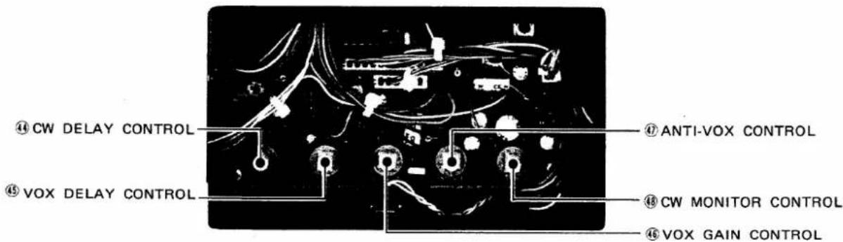
text_image
④ CW DELAY CONTROL ⑤ VOX DELAY CONTROL ⑥ ANTI-VOX CONTROL ⑧ CW MONITOR CONTROL ⑭ VOX GAIN CONTROL44. CW DELAY CONTROL
In semi-break-in operation, this controls the transmit/receive switchover time-delay. Adjust to suit your keying speed.
(Note: If the delay is set to the shortest position, it will reach almost full break-in CW.)
45. VOX DELAY (VOX time constant) CONTROL
This controls the transmit to receive switching time. Adjust it so transmit to receive switching will not occur during short pauses in normal speech.
46. VOX GAIN CONTROL
This control adjusts the input signal level via the microphone to the VOX circuit. For VOX operation in SSB, adjust the control so that the VOX circuit will operate with normal speech.
47. ANTI-VOX CONTROL
In VOX operation, the VOX circuit may be operated by sound from the speaker causing a switch to transmit. This trouble can be prevented by adjusting the input level of the ANTI VOX circuit with this control along with the VOX gain control so that the VOX circuit only operates from the operator's voice, not by sound from the speaker.
48. CW MONITOR (MONI) CONTROL
This control adjusts the audio volume of the side-tone (monitor) audio during CW transmit operation. Adjust it to your desired level for easy listening.
4-3 REAR PANEL CONNECTIONS
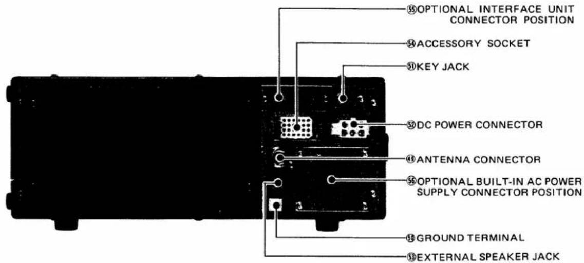
text_image
55 OPTIONAL INTERFACE UNIT CONNECTOR POSITION 54 ACCESSORY SOCKET 50 KEY JACK 52 DC POWER CONNECTOR 49 ANTENNA CONNECTOR 56 OPTIONAL BUILT-IN AC POWER SUPPLY CONNECTOR POSITION 50 GROUND TERMINAL 53 EXTERNAL SPEAKER JACK49. ANTENNA (ANT) CONNECTOR
This is used to connect the antenna to the set. Its impedance is 50 ohms and connects with an N type (UG-21/U) connector.
50. GROUND TERMINAL
To prevent electrical shock, TVI, BCI and other problems, be sure to ground the equipment through the GROUND TERMINAL. For best results use as heavy a gauge wire or strap as possible and make the connection as short as possible, even in mobile installations.
51. KEY JACK
For CW operation, connect a key here. For electronic keying the closed key terminal voltage must be less than 0.4V DC.
52. DC POWER SOCKET
For connection of the IC-PS15's DC power cord, or other suitable power supply.
53. EXTERNAL SPEAKER JACK
When an external speaker is used, connect it to this jack. Use a speaker with an impedance of 8 ohms. When the external speaker is connected, the built-in speaker does not function.
54. ACCESSORY SOCKET
Various functions are available through the accessory socket such as modulation output, receiver output, T/R change-over, and so forth. Refer to the ACCESSORY SOCKET CONNECTION on page 28.
55. OPTIONAL INTERFACE UNIT (IC-EX309) CONNECTOR POSITION
This is provided to install the DP-25 connector of the optional interface unit, IC-EX309.
56. OPTIONAL BUILT-IN AC POWER SUPPLY SOCKET POSITION
This is provided to install AC power socket plate of the optional built-in AC power supply, IC-PS35.
SECTION 5 OPERATING INSTRUCTIONS
5 - 1 HOW TO TUNE
The following instructions are for tuning in any mode. Please read carefully and understand fully before turning ON your unit. Proper tuning is necessary for optimum operation.
5-1-1 PRESET
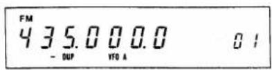
When the power switch is turned ON, the frequency display shows frequency, mode and duplex mode (if stored) stored in the VFO A, letters "VFO A" and "01" representing memory channel 1, and the set initiates with VFO A and displayed mode, even if the previous operating mode was different. In addition, the RIT and SCAN are turned OFF.
FOR EXAMPLE:
5-1-2 FREQUENCY DISPLAYED ON EACH MODE By selecting the various modes, the displayed frequency will be changed as follows.
| On the "FM" mode | 435.000.0 |
| On the "USB" mode | 434.998.5 |
| On the "LSB" mode | 435.001.5 |
| On the "CW" mode | 434.999.3 |
The displayed frequency shows the carrier frequency. To avoid the trouble of recalibrating the dial when you change the operating mode, the displayed frequency is set to shift to the carrier frequency of each mode automatically. For the differences of frequency shifts of the various modes, refer to the following figure.
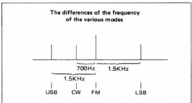
text_image
The differences of the frequency of the various modes 700Hz 1.5KHz USB CW FM LSBWhen pushing one of the MHz UP/DOWN switches to change the operating frequency, 100KHz and lower digits of the frequency display will remain as it had in the previous display.
FOR EXAMPLE:
When the frequency display shows "432.471.5", and if you push the UP switch to 433MHz range, the frequency display will show "433.471.5" representing 433.4715MHz.
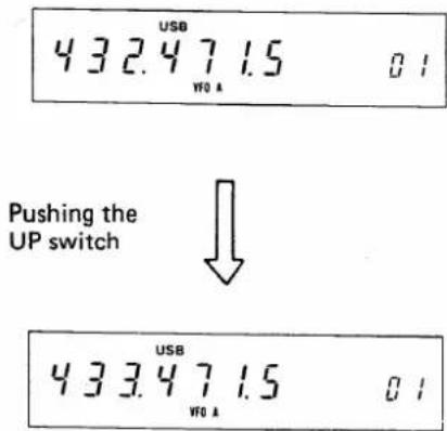
text_image
432.471.5 01 VFO A Pushing the UP switch 433.471.5 01 VFO A5-1-3 TUNING CONTROL
Rotating the TUNING CONTROL clockwise increases the frequency, while turning counterclockwise decreases the frequency in 10Hz steps in the USB, LSB, and CW modes, and in 5KHz steps in the FM mode.
If the 10Hz steps tuning rate is selected, rapid rotation of the tuning control knob will cause the 100Hz step rate to be automatically selected.
When the TUNING RATE switch is pushed in, the 1KHz steps tuning rate is selected in any mode. At this time, the 100Hz digit of the frequency display is cleared to "0".
When you reach 440.000.0 (U.S.A. version: 450.000.0), turning the tuning control clockwise will bring the operating frequency to 430.000.0, the lowest edge, and you can continue increasing the frequency from there by continuing to rotate the control clockwise. The VFO endless system functions in the same way when decreasing the frequency from 430.000.0, and will prevent you from inadvertently operating out of the amateur radio band.
FOR EXAMPLE:
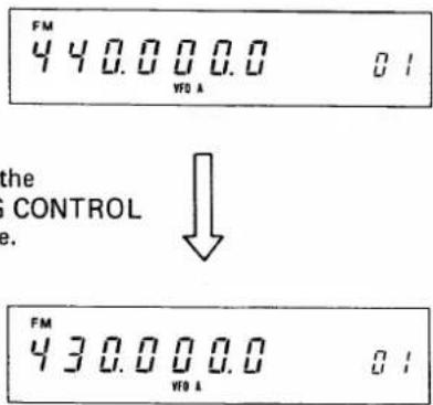
text_image
FM 4 40.0000.0 WTO A the CONTROL e. ↓ FM 430.0000.0 WTO A 01Brake Adjustment
If the control is too loose or too stiff for comfortable use, you can adjust the torque by tightening or loosening the brake adjustment screw accessible from underneath the set.
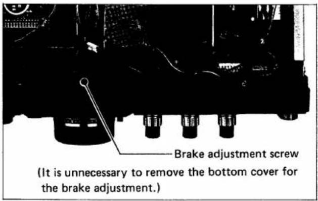
text_image
Brake adjustment screw (It is unnecessary to remove the bottom cover for the brake adjustment.)The following instructions should be used to adjust the tension of the Tuning control.
- The Tuning control tension will become tighter by turning the brake adjustment screw clockwise, and will become looser by turning the screw counterclockwise.
- While performing this adjustment, the Tuning control must be turned continuously as the screw is adjusted in order to set the tension for a comfortable touch.
5-1-4 DIAL LOCK SWITCH
After the IC-471H is set at a certain frequency for rag chewing, mobile operation, etc., by pushing the Dial Lock switch the VFO is locked at the displayed frequency, thus inactivating the operation of the tuning control. To change the frequency, the Dial Lock must first be disengaged by pushing and releasing the Dial Lock switch again.
NOTE: When the letters "VFO A" or "VFO B" are displayed on the frequency display, we call this condition "VFO MODE", when the letters "MEMO" are displayed above the memory channel number, we call "MEMORY CHANNEL MODE".
These can be changed by pushing the VFO/MEMORY switch alternately.
5-1-5 VFO SWITCH
The IC-471H contains two VFO's for both receiving and transmitting. The VFO's are labeled "VFO A" and "VFO B", and are selectable by pushing the VFO switch alternately in the VFO MODE. The dual VFO system gives the IC-471H many very convenient features. Please read this section very carefully and perform the operation several times until you are comfortable with the system. Try the example for practice!
-
"VFO A" is for both receiving and transmitting, and selected by pushing the VFO switch. The receive and transmit frequency will be controlled by "VFO A", displayed on the frequency display, and stored in the "A" memory.
-
"VFO B" is for both receiving and transmitting, and selected by pushing the VFO switch. The receive and transmit frequency will be controlled by the "VFO B", displayed on the frequency display, and stored in the "B" memory.
Switching from one VFO to the other VFO does not clear the first VFO. The frequency and operating mode (and duplex mode if any) are retained in the VFO's memory.
FOR EXAMPLE:
If 432.125MHz and USB are set with "VFO A", then the VFO switch is pushed to select "VFO B", the frequency display will show VFO B's frequency and mode, but 432.125MHz and USB are still stored in VFO A's memory. Pushing the VFO switch again to return to VFO A, "432.125.0" and "USB" will be displayed on the frequency display.
Accordingly, if the VFO switch is pushed again to select VFO B, the frequency and mode that were set with VFO B will appear.
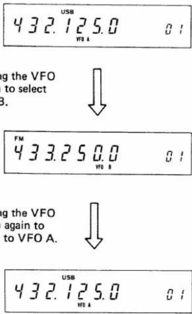
text_image
432.125.0 VFO A g the VFO to select B. ↓ FM 433.250.0 VFO B g the VFO again to to VFO A. ↓ 432.125.0 VFO A 01This allows you to set a certain frequency with one VFO, work up and down the band with the other VFO, and periodically check the set frequency simply by switching between VFO "A" and "B".
It also allows you to search for a clear frequency with one VFO, while keeping your operating frequency on the other VFO. When you have found a clear frequency, switch back to your operating frequency, inform the station you are in contact with of the new frequency, and switch back. It's that simple!
5-1-6 SPLIT SWITCH
The SPLIT switch changes the relationship of the two VFO's. In the OFF (out) position, one VFO is for both
receive and transmit. In the ON (pushed in) position, one VFO is for receive and the other is for transmit, so that this will allow you to operate on split receive/transmit frequencies.
FOR EXAMPLE:
Set VFO A to 432.471.0MHz and VFO B to 432.771.0MHz. Push the VFO switch to return VFO A then push the SPLIT switch to ON. "432.471.0" will be shown on the display during receive (VFO A) and "432.771.0" during transmit (VFO B). You are now receiving on 432.471.0 MHz and transmitting on 432.771.0MHz. Push the VFO switch to reverse the above.
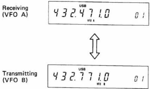
text_image
Receiving (VFO A) 432.471.0 01 Transmitting (VFO B) 432.771.0 01Each VFO stores the operating mode too. If a different mode is stored in each VFO, a crossmode QSO can be possible as well.
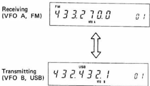
text_image
Receiving (VFO A, FM) FM 4 3 3.2 70.0 VFO A Transmitting (VFO B, USB) USB 4 3 2.4 3 2.1 VFO B 015-1-7 TRANSFERRING VFO FREQUENCY
The VFO EQUALIZING switch allows either VFO to be brought to the exact frequency of the other VFO without turning the tuning control, and the operating mode.
FOR EXAMPLE:
When VFO A is 432.471MHz and USB, and VFO B is 433.770MHz and FM DUPLEX, pushing the VFO switch to select VFO A, then the VFO EQUALIZING switch, VFO B's frequency and operating mode become the same as VFO A's (432.471MHz and USB SIMPLEX). Now VFO A's frequency is memorized in VFO B, and you can operate anywhere with VFO A or B. When you want to return to the previous frequency (432.471MHz), switch back to the other VFO. To reverse this (A the same as B), select VFO B first, then the VFO EQUALIZING switch.
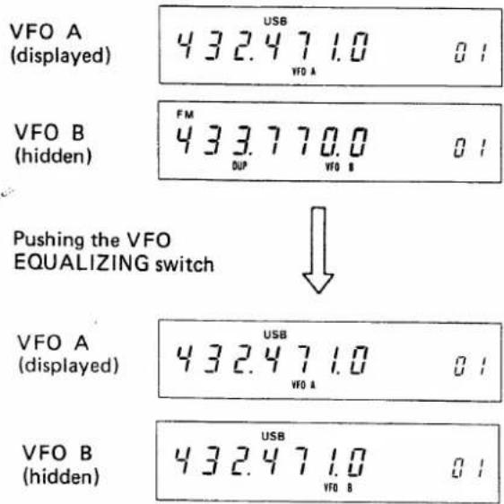
other
| Category | Value | |---|---| | VFO A (displayed) | 432.471.0 | | VFO A (hidden) | 0.1 | | VFO B (hidden) | 433.770.0 | | VFO B (hidden) | 0.1 | Pushing the VFO EQUALIZING switch ↓ VFO A (displayed) | 432.471.0 | | Pushing the VFO EQUALIZING switch ↓ VFO A | 0.1 | | VFO B (hidden) | 432.471.0 | | VFO B (hidden) | 0.1 |5-1-8 RIT (RECEIVE INCREMENTAL TUNING)
By using the RIT circuit, you can shift the receive frequency 9.9KHz (maximum) on either side of the transmit frequency without moving the transmit frequency itself. Therefore, when you get a call slightly off frequency, or when the other station's frequency has drifted, you can tune in the frequency without disturbing the transmit frequency.
By pushing the RIT switch, the RIT circuit is turned ON and the letters "RIT" and the shifted frequency are displayed on the frequency display.
The receive frequency can be shifted in 10Hz steps by turning the RIT CONTROL.

text_image
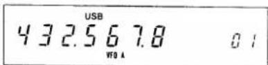
First push the RIT switch to turn ON the RIT. 4 3 2.5 6 7.8 0.0 01 USB VIO A(Receiving and transmitting on 432.5678MHz.)

text_image
Turning the RIT control counter- clockwise. 4 3 2.5 6 7.8 -3.9 01 USB W0 A RIT(Receiving on 432.563.9MHz and transmitting on 432.567.8MHz.)
Rotating the control to the (+) direction raises the receiving frequency, and to the (−) direction lowers one.
To turn OFF the RIT function, push the RIT switch again and the letters "RIT" and the shifted frequency displayed on the frequency display will go OFF. When the RIT circuit is OFF, the transmit and receive frequencies are the same regardless of the shifted frequency. However, the shifted frequency is stored in the memory and it will reappear when the RIT switch is pushed again.
Push the RIT switch to turn OFF the RIT.
Push the RIT switch again to turn ON the RIT. 432.567.8-3.901
To clear the shifted frequency, push the RIT CLEAR button and the shifted frequency becomes "0.0" (The receive and transmit frequencies become the same.), regardless the RIT circuit is turned ON or OFF.
Push the RIT CLEAR button. 432.567.8 RIT WO A 0.001
NOTE: The RIT circuit is operational when the frequency has been locked with the DIAL LOCK button as well as in the MEMORY CHANNEL MODE.
When the transmitting and receiving frequencies differ by more than 10KHz, use VFO A and B in the SPLIT mode.
5-1-9 +DUPLEX AND -DUPLEX BUTTONS (DUPLEX OPERATION)
These buttons allow DUPLEX (repeater) operation. The offset frequency is preset for the standard separation, 7.6MHz (U.S.A. version: 5.0MHz), but this frequency can be reset for any 10KHz steps in-band frequency. So you can access any repeater.
- When the set is in SIMPLEX mode (a duplex button has not been pushed and the letters "DUP" or"—DUP" are not displayed.); the receive frequency and transmit frequency are controlled with the displayed frequency which is set by a VFO or MEMORY CHANNEL.
- When the +DUPLEX button is pushed, the set is in DUPLEX mode and the transmit frequency is set 7.6MHz (U.S.A. version: 5.0MHz) (or reset offset frequency) above the receive frequency. At the same time, the letters "DUP" are displayed on the frequency display. To turn off the DUPLEX mode (to set into the SIMPLEX mode), push the +DUPLEX button or -DUPLEX button once.
- When the -DUPLEX button is pushed, the set is in the DUPLEX mode and the transmit frequency is set 7.6MHz (U.S.A. version: 5.0MHz) (or reset offset frequency) below the receive frequency, and the letters “-DUP” are displayed. To turn off the DUPLEX mode, push the +DUPLEX or -DUPLEX button once.
- When the set is in the DUPLEX mode, while the CHECK button is pushed, the receive frequency becomes the expecting transmit frequency, so you can receive a repeater's input frequency.
Pushing the "+DUPLEX" or -DUPLEX" button will allow you to access a repeater that has a 7.6MHz (U.S.A. version: 5.0MHz) input/output frequency separation.
FOR EXAMPLE: (Different for U.S.A. version)
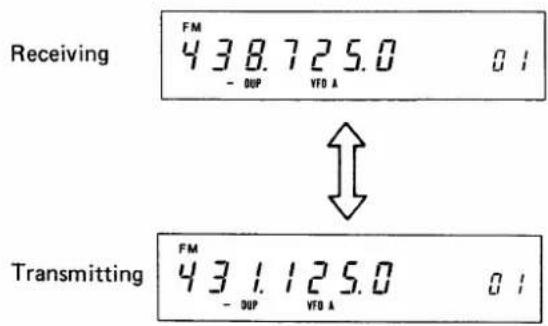
Set the displayed frequency to 438.725MHz. Then push the “-DUPLEX” button. “438.725.0” and the letters “-DUP” will be shown on the display during receive and “431.125.0” during transmit. You are now receiving on 438.725MHz and transmitting on 431.125MHz, so you can access a 431.125/438.725 repeater.
text_image
Receiving FM 438.725.0 - DUP VTO A 01 Transmitting FM 431.125.0 - DUP VTO A 01If you push the CHECK button, "431.125.0" will be shown on the display and you can receive on 431.125MHz, i.e., repeater input frequency, while the button is pushed.
The CHECK button is depressed (both in receive and transmit modes.)
If you change the receive frequency from 438.725MHz to 438.675MHz, the transmit frequency will change from 431.125MHz to 431.075MHz, so now you can access a 431.075/438.675 repeater.
Pushing the "+DUPLEX" button twice changes the transmitting frequency to 7.6MHz above the receive frequency.
If you set the receive frequency to 431.120MHz, the transmitting frequency will be 438.720MHz.
These functions will be available with any VFO's and MEMORY CHANNELS.
5-1-10 RESETTING THE OFFSET FREQUENCY
The offset frequency can be reset to any 10KHz steps in-band frequency other than 7.6MHz (U.S.A. version: 5.0MHz) for each VFO.
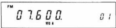
In the FM mode, by pushing the OFFSET WRITE button, the FREQUENCY DISPLAY shows 10MHz to 1KHz digits of the offset frequency instead of the operating frequency. If no offset frequency has been reset since turning the power of the set ON, "07.600" (U.S.A. version: "05.000") will be shown on the display.
Select a VFO. While the OFFSET WRITE button is pushed, rotating the tuning control clockwise increases the offset frequency; turning it counterclockwise decreases the frequency in 10KHz steps. Turn the tuning control to obtain the desired offset frequency, then release the OFFSET WRITE button, and the desired offset frequency is
written into the CPU and maintained until a new offset frequency is reset.
NOTE: OFFSET WRITE can be reset on FM mode only in 10KHz steps, however if the TUNING RATE SWITCH has been pushed ON, OFFSET WRITE can be reset on any mode with 1KHz steps.
What to do if you want to operate repeaters that have a frequency separation other than 7.6MHz (U.S.A. version: 5.0MHz) (for example; 4.6MHz).
FOR EXAMPLE:
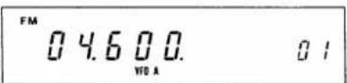
Select VFO A and FM mode, then push the OFFSET WRITE button, and the FREQUENCY DISPLAY shows "07.600". While pushing the OFFSET WRITE button, turn the tuning control counterclockwise to show "04.600" on the display, then release the OFFSET WRITE button.
Displayed while push- ing the OFFSET WRITE button.
Displayed by turning the TUNING CONTROL while the OFFSET WRITE button is pushed.
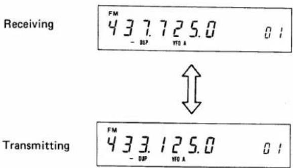
Push the -DUPLEX button to show “-DUP” on the display and tune to 437.725MHz. “437.725.0” will be shown on the display during receive and “433.125.0” during transmit.
You are now receiving on 437.725MHz and transmitting on 433.125MHz, so you can access a 433.125/437.725 repeater.
other
| Signal | Value | | :--- | :--- | | Receiving | 437.725.0 | | Transmitting | 433.125.0 |If you change the receiving frequency from 437.725MHz to 437.675MHz, the transmitting frequency will change from 433.125MHz to 433.075MHz, so now you can access a 433.075/437.675 repeater.
5-1-11 DIAL FUNCTION SELECT SWITCH (IN VFO MODE)
In the VFO mode, by pushing the DFS (DIAL FUNCTION SELECT) switch in, the operating frequency is locked on the displayed frequency and by turning the TUNING CONTROL, the MEMORY CHANNEL NUMBER displayed on
the frequency display can be changed. This is very convenient to memorize the operating frequency and modes into a memory channel, or to change the operating frequency and modes to ones in a memory channel.
FOR EXAMPLE:
Now you are operating on 432.471MHz and USB, and memory channel number "07" is displayed. If you want to memorize these into memory channel 27, push the DFS switch in and you can change the displayed memory channel number by turning the tuning control.
Turn the tuning control to obtain the desired memory channel number (at this time "27"), then push the MEMORY WRITE button, and the operating frequency "432.471MHz" and mode "USB" are memorized into memory channel 27. To change the operating frequency again, push and release the DFS switch.

text_image
On the display 432.471.0 87 Pushing the DFS switch and turning the TUNING CONTROL. 432.471.0 27By pushing the MEMORY WRITE button, the frequency and mode are memorized into the MEMORY CHANNEL 27.
FOR EXAMPLE:
Now you are operating on 432.471MHz USB and memory channel 7 memorizes "438.725MHz", "FM" and"—DUP". If you wish to operate with the frequency and modes which are memorized in the memory channel 7, push the DFS switch in and turn the tuning control to display memory channel number "07". Then push the FREQUENCY TRANSFER button, and "438.725.0", "FM" and"—DUP" appeare on the frequency display. Now you can operate on this frequency and modes, and by pushing and releasing the DFS switch, the displayed frequency can be changed by turning the tuning control.
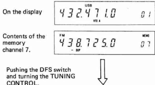
text_image
On the display 432.471.0 VFD A Contents of the memory channel 7. FM 438.725.0 - DUP MEMO 07 Pushing the DFS switch and turning the TUNING CONTROL.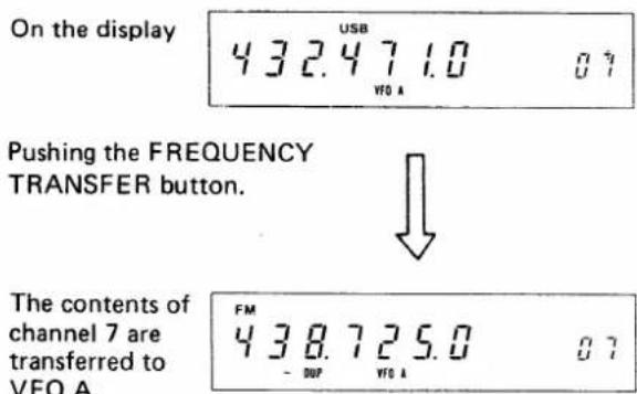
text_image
On the display 432.471.0 USB VFO A Pushing the FREQUENCY TRANSFER button. The contents of channel 7 are transferred to VFO A. FM 438.725.0 - DUP VFO A 075-2 MEMORY CHANNEL OPERATION
5-2-1 MEMORY CHANNEL SELECTION
When the power switch is turned ON, the set initially operates with VFO A, and memory channel number "01" is displayed. By pushing the VFO/MEMORY switch, the set is switched into the MEMORY CHANNEL MODE and frequency, mode and duplex mode (if memorized) which have been stored in the "MEMORY CHANNEL 1" are displayed on the frequency display. In addition, the letters "MEMO" are also displayed above the memory channel number to indicate the set is in the MEMORY CHANNEL MODE.
FOR EXAMPLE:
When "432.471MHz" and USB are memorized in VFO A, and "438.725MHz", "FM" and "-DUP" are in MEMORY CHANNEL 1, pushing the power switch ON, the frequency display shows "432.471.0", "USB", "VFO A" and memory channel number "01".
By pushing the VFO/MEMORY switch, the display will show "438.725.0", "FM", "-DUP", memory channel number "01", and the letters "MEMO" above the channel number.
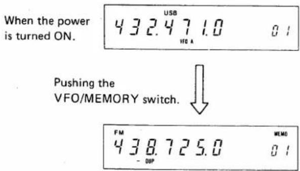
text_image
When the power is turned ON. 432.471.0 01 VFO A Pushing the VFO/MEMORY switch. FM MEMD 438.725.0 01 - DUPBy turning the TUNING CONTROL, memory channels can be selected. Turning clockwise increases the channel number and counterclockwise decreases the number, and the respective frequency, mode and duplex mode (if memorized), are displayed on the display.
When you select a memory channel that has never been programmed, the frequency display does not show any frequency, but MHz and KHz decimals. However, the set works with the frequency and mode of the memory channel (or VFO), which was previously displayed.
FOR EXAMPLE:
When "432.172MHz" and "CW" are memorized in memory channel 2, and no frequency is in the channel 3, by turning the TUNING CONTROL clockwise, the frequency display will show "432.172.0", "MEMO" and memory channel number "02".
By turning the TUNING CONTROL clockwise furthermore, the memory channel number will change to "03", but the channel has never memorized any frequency, thus the display shows "CW" and only the MHz and KHz decimals. However, the set works with the frequency and mode of channel 2, i.e., "432.172MHz" and "CW".
When memory channel limits are reached (i.e., "01" or "32"), the next memory channel entered will be the opposite limit (i.e., "32" or "01").
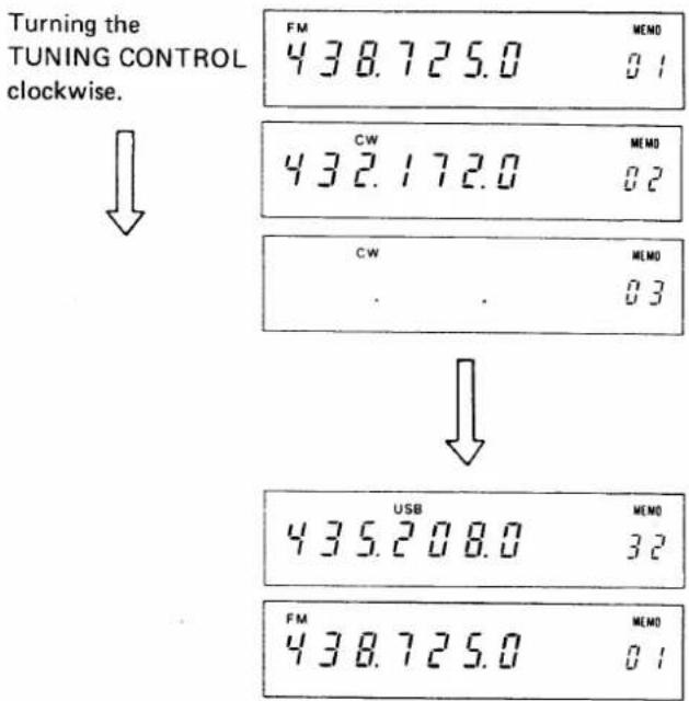
text_image
Turning the TUNING CONTROL clockwise. ↓ FM 438.725.0 MEMO 01 CW 432.172.0 MEMO 02 CW MEMO . . 03 ↓ USB MEMO 435.208.0 32 FM 438.725.0 MEMO 015-2-2 DIAL FUNCTION SELECT SWITCH (IN MEMORY CHANNEL MODE)
In the MEMORY CHANNEL MODE, by pushing the DFS (DIAL FUNCTION SELECT) switch in, the operating memory channel is locked on the displayed one and by turning the TUNING CONTROL, the OPERATING FREQUENCY displayed on the frequency display can be changed. This is very convenient for tuning slightly off frequency, or changing the operating frequency, or rewriting the memorized frequency in the selected memory channel.
FOR EXAMPLE:
Now you are operating on 432.471MHz and USB with memory channel 7. If you want to change this frequency, push the DFS switch in and adjust the TUNING CONTROL. Turning the TUNING CONTROL clockwise increases the frequency and counterclockwise decreases it, the same as a VFO.
To tune to "432.495MHz", turn the TUNING CONTROL clockwise to obtain the desired frequency "432.495.0" on the display.
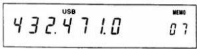
Pushing the DFS switch in, and turning the TUNING CONTROL.

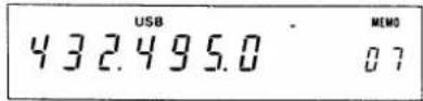
If you wish to transfer this operating frequency (432.495 MHz) and mode (USB) into a VFO, push the FREQUENCY TRANSFER button, and the operating frequency "432.495 MHz" and mode "USB" are transferred into a VFO previously selected.
NOTE: Don't push the VFO/MEMORY switch before pushing the FREQUENCY TRANSFER button to transfer the operating frequency (at this time, 432.495MHz), or the operating frequency is erased and the original memorized frequency (432.471MHz) will be transferred into a VFO.
If you wish to rewrite the memorized frequency in the selected channel (at this time, "07") to this frequency ("432.495.0"), push the MEMORY WRITE button, and the operating frequency "432.495MHz" and mode "USB" are memorized into the memory channel 7.
To change the operating memory channel again, push and release the DFS switch, then turn the TUNING CONTROL.
5-2-3 MEMORY-WRITE (PROGRAMMING THE MEMORY CHANNELS)
Any operating frequency, mode, duplex mode, offset frequency, and tone encoder/decoder tone number (if installed) can be memorized into a memory channel.
-
Set the desired operating frequency, mode and duplex mode (if desired). For example, set them for "438.725 MHz", "FM" and -DUP with 7.6MHz offset by using VFO B.
-
Push the DFS switch in, then select a memory channel to be memorized by turning the TUNING CONTROL. For example, select it at memory channel 10.
-
To check the contents in the memory channel, push the VFO/MEMORY switch, and the contents are displayed on the frequency display. If you don't want to erase these contents, select another memory channel which has contents erasable or no memorized frequency. (When no frequency has been memorized, only the MHz and KHz decimals are displayed at the frequency position.) After checking, push the VFO/MEMORY switch again to return to the VFO.
-
One push of the MEMORY WRITE button erases the previous memorized contents (if any) and memorizes the displayed frequency, mode, duplex mode (including offset frequency) and so on into the selected memory channel (at this time channel 10).
- Memorize other desired frequencies, etc into other memory channels in the same manner. Memory channel 1 and 2 are used also for the PROGRAMMED SCAN. For PROGRAMMED SCAN operation, refer to "SCANNING OPERATION on page 16.
Frequency, mode and duplex mode to be memorized.
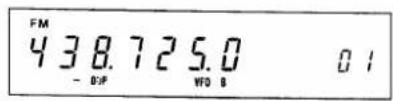
Pushing the DFS switch in, and turning the TUNING CONTROL.

Pushing the VFO/MEMORY switch to check contents of the channel.
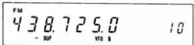
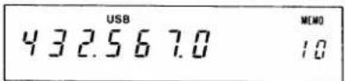
Pushing the VFO/MEMORY switch to return to the VFO, then pushing the MEMORY WRITE button.

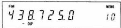
(This is displayed after pushing the VFO/MEMORY switch.)
5-3 TUNING BY UP/DOWN BUTTONS ON THE MICROPHONE
5-3-1 FREQUENCY CONTROL
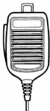
With each push of the UP or DN (down) button on the supplied microphone, the operating frequency is changed one increment up or down respectively. In the same way, by depressing the button continuously, the operating frequency is changed up or down the same as turning the TUNING CONTROL. The tuning rate is according to the operating mode and setting of the TUNING RATE switch.
natural_image
Line drawing of a handheld electronic device with ventilation slots and a coiled cable (no text or symbols)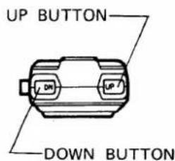
text_image
UP BUTTON DOWN BUTTONThis function is effective in the VFO mode and when the DFS switch is pushed in to change the operating frequency in the MEMORY CHANNEL mode.
5-3-2 MEMORY CHANNEL SELECTING
When in the MEMORY CHANNEL mode or when the DFS and VFO/MEMORY switches are pushed in, the displayed memory channel number changes by depressing the UP or DN (down) button on the microphone continuously. The operating MEMORY CHANNEL or displayed channel number is changed up or down respectively every two seconds.
5-4 SCANNING OPERATION
The IC-471H provides various scanning operations. Please read the following instructions carefully to fully enjoy the IC-471H's many capabilities.
5-4-1 MEMORY SCAN
This is used to scan all programmed memory channels continuously.
- Program your desired frequencies into memory channels.
- Select a memory channel programmed with a frequency. (The scan cannot start from a blank channel.)
- Depress the SCAN START/STOP button, and the frequency starts scanning the programmed frequencies in the memory channels from the highest channel to lowest. At this time, the scan skips blank channels, if any.
- If the SQUELCH is engaged, the scan stops when the squelch is opened and a signal is received. The scan restarts after a specified delay time.
To stop scanning without opening the squelch, depress the SCAN START/STOP button. Depress it again to restart the scanning.
5-4-2 MODE SELECTIVE SCAN
In the memory scan mode, by pushing the MODE SELECTIVE SCAN switch in, the scan scans only on channels having the desired operating mode.
To be in this scan mode, first, select a channel that has your desired mode, second, push the MODE SELECTIVE switch in, then the SCAN START/STOP button.
When the set is scanning in the normal memory scan mode, push the MODE SELECTIVE switch in at the moment that your desired mode is displayed on the display.
5-4-3 PROGRAMMED SCAN
This is to scan between two desired frequencies, which are memorized in the memory channels "1" and "2".
- Memorize the frequencies of the high and low edges of the desired scanning range into the memory channels 1
and 2. Regardless of which channel the higher frequency is memorized in, the scan starts from the high edge of the range.
For example, 432.200MHz is in the memory channel 1 and 432.800MHz in the channel 2.
-
Place the set in the VFO MODE and select a VFO you desire. Pushing the SCAN START/STOP button starts the scan from the high edge (432.800MHz) to the low edge (432.200MHz). The scanning frequency increments depend on the operating mode selected and the TUNING RATE SELECT switch setting.
-
When the scanning frequency reaches the low edge (432.200MHz), it automatically returns to the high edge (432.800MHz) and continues scanning down to provide endless scanning operation.
-
While the SQUELCH is engaged, the squelch opens when a signal is received and will stop the scanning automatically on the frequency, and the signal can be monitored. After approximately 10 seconds, the scan restarts from the frequency the scan stopped at, continuing to the low edge. If the RECEIVE indicator is lit because the SQUELCH is not engaged, the scan does not stop at any signals.
-
Depressing the SCAN START/STOP button while the scan is operating or during the 10 seconds of monitoring, clears the scanning operation and the VFO goes back to normal operation.
-
By turning the set into the transmit mode, or rotating the TUNING CONTROL, or pushing the VFO switch, RIT switch, VFO/MEMORY switch, CHECK button or one of the MODE SELECT switches the scan stops and clears.
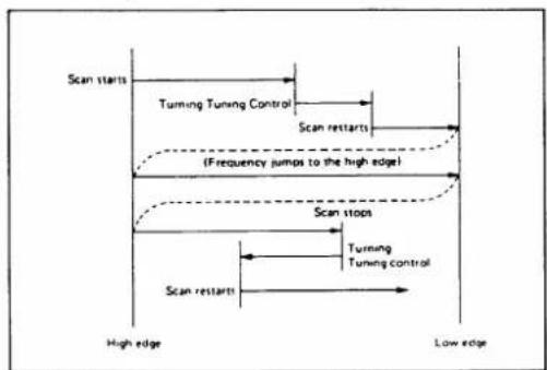
flowchart
graph TD
    A["Scan starts"] --> B["Turning Tuning Control"]
    B --> C["Scan restarts"]
    C --> D["(Frequency jumps to the high edge)"]
    D --> E["Scan stops"]
    E --> F["Turning Tuning control"]
    F --> G["Scan restarts"]
    G --> H["High edge"]
    G --> I["Low edge"]
- When the operating frequency is higher than the high edge (432.800MHz) and the SCAN START/STOP button is pushed, the scan starts from the operating frequency and scan down to the low edge, but it will return to the memorized high edge frequency (432.800 MHz) and continue the scanning to the low edge. If the operating frequency is below the low edge frequency (432.200MHz), the scan frequency jumps to the high edge frequency (432.800MHz) and starts from the high edge.
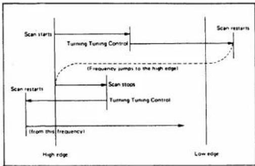
flowchart
graph TD
    A["Scan starts"] --> B["Turning Tuning Control"]
    B --> C["(Frequency jumps to the high edge)"]
    C --> D["Scan stops"]
    D --> E["Turning Tuning Control"]
    E --> F["(from this frequency)"]
    F --> G["High edge"]
    G --> H["Low edge"]
    H --> I["Scan restarts"]
NOTE: The auto-stop functions with SSB or CW signals, but the scan does not always stop at the exact carrier frequency. When the scan stops on a signal, tune into the signal for better reception by pushing a MODE switch for the proper mode (if different) and by rotating the TUNING CONTROL.
5-4-4 RESUMING SCAN
All scan modes are provided with the resume scan function. When the scan has been stopped by the auto-stop function, the scan will restart after a specified delay time (about 10 seconds).
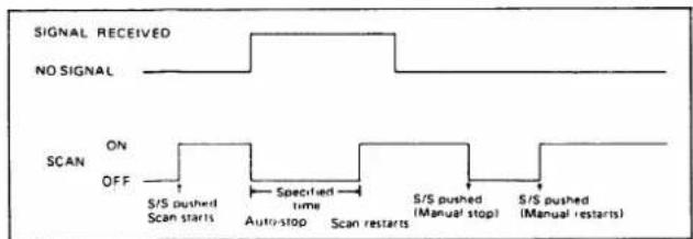
text_image
SIGNAL RECEIVED NO SIGNAL SCAN ON OFF S/S pushed Scan starts Specified time Auto-stop Scan restarts S/S pushed (Manual stop) S/S pushed (Manual restarts)5 - 5 SSB OPERATION
5-5-1 RECEIVING
After connecting an antenna, microphone, etc., set knobs and switches as follows.
| POWER SWITCH | OFF (OUT) |
| T/R SWITCH | RECEIVE (DOWN) |
| VOX SWITCH | OFF (OUT) |
| NOISE BLANKER SWITCH | OFF (OUT) |
| AGC SWITCH | SLOW (OUT) |
| METER SWITCH | OFF (OUT) |
| PREAMP SWITCH | OFF (OUT) |
| AF GAIN CONTROL | Completely Counterclockwise |
| RF GAIN CONTROL | Completely Clockwise |
| SQUELCH CONTROL | Completely Counterclockwise |
| TONE CONTROL | Center (12 o'clock) position |
| TUNING RATE SWITCH | OFF (OUT) |
| DFS SWITCH | OFF (OUT) |
| SPLIT SWITCH | OFF (OUT) |
| DIAL LOCK SWITCH | OFF (OUT) |
Now push the POWER switch in. The meter lamp will be
illuminated, after a few seconds, a frequency and mode memorized in the VFO A, and memory channel number "01" will be shown on the frequency display.
Push the desired mode switch (USB or LSB), if the displayed mode is different than the desired one.
In-SSB operation there are both USB (upper side band) and LSB (lower side band). USB is usually used on the band, while LSB is usually used for satellite communications. Select the mode according to your use.
Slowly turn the AF GAIN control clockwise to a comfortable level. Rotate the tuning knob until a signal is received. The meter needle will move according to the signal strength, so tune for the highest possible meter reading and the clearest audio. If you cannot get a clear signal, you may be receiving in the opposite sideband. If so, change the mode to the proper sideband.
Adjust the RF GAIN control and TONE control for comfortable reception.
If squelch operation is required to cut out noise when no signal is received, turn the SQUELCH control clockwise until the noise from the speaker stops and leave it just below this threshold.
For tuning, memory channel operation and scanning operation, please refer to 5 - 1 HOW TO TUNE on page 9, 5 - 2 MEMORY CHANNEL OPERATION on page 14 and 5 - 4 SCANNING OPERATION on page 16.
5-5-2 NOISE BLANKER
Push the NB (NOISE BLANKER) switch in when there is pulse type noise, such as ignition noise from automobile motors. The noise will be suppressed and even weak signals will be received comfortably. The noise blanker may not work as effectively when there is a strong signal on a nearby frequency or when there is continuous (not pulse type) noise.
5-5-3 AGC (AUTOMATIC GAIN CONTROL)
The IC-471H has a fast attack/slow release AGC system which holds the peak voltage of rectified IF signals from the IF amplifier circuit for a certain period, facilitating reading of the S-meter function.
For normal SSB reception, set the AGC switch in the OUT (slow) position. When tuning or receiving signals with short interval fading, set the AGC switch in the FAST (pushed IN) position. At this time, the time constant of the circuit is shortened.
5 - 5 - 4 PREAMP SWITCH (When external preamp unit is installed)
Push the PREAMP switch in when receiving weak signals. In the pushed-in position, an RF preamplifier is inserted
into the receiving antenna circuit, increasing sensitivity and giving easy reception.
5-5-5 TRANSMITTING
Before transmitting, listen in the receive mode to make sure your transmission will not interfere with other communications. If possible, use a dummy load for adjustment instead of an antenna. Set the MIC GAIN and RF POWER controls as follows.
MIC GAIN CONTROL CENTER (12 o'clock) position RF POWER CONTROL Completely counterclockwise
Other knobs and switches are set as the same for receiving. When the T/R switch is turned to transmit, or when the PTT (push-to-talk) switch on the microphone is depressed, the TRANSMIT indicator is illuminated.
By speaking into the microphone, the meter needle will move according to the strength of your voice and SSB signals will be transmitted.
Hold the microphone about three inches from your mouth and speak in a normal voice. The supplied microphone is of an electret condenser type and provides good pickup for all voice levels. Speaking too loudly into the microphone does not increase the RF output power, but causes some distortion in the SSB signals or spurious radiation.
If you wish to increase the output power, turn the RF POWER control clockwise and adjust to obtain the desired RF output power of between 10 watts and 75 watts (approximately).
To return to the receive mode, turn the T/R switch to receive, or release the microphone PTT switch.
5-5-6 VOX OPERATION
The IC-471H has a built-in VOX (voice operated relay) which allows automatic T/R switching by voice signals into the microphone. For VOX use, set the knobs inside the top access cover as follows:
VOX GAIN CONTROL Fully counterclockwise VOX DELAY CONTROL Fully clockwise ANTI VOX CONTROL Fully counterclockwise
Push the VOX switch on the front panel IN. Leaving the T/R switch in the receive position and without pushing the PTT switch, turn the VOX GAIN control clockwise while speaking into the microphone. At a certain point, the T/R switching circuit will be activated by your voice. This is the proper position for the VOX GAIN control. Set the VOX GAIN control at a level which provides for T/R switching at your normal voice level.
Transmit-release time (the time delay before the set automatically returns to receive when you stop talking) is controlled by the VOX DELAY control. Turning the control counterclockwise makes the time shorter. Set it at a position which is comfortable and which allows for short pauses in normal speech.
Adjust the ANTI VOX control so that the VOX circuit is not activated by sounds from the speaker by turning the control clockwise while receiving a signal.
5 - 6 CW OPERATION
5-6-1 RECEIVING
For CW reception, push the CW mode switch. The letters "CW" should be displayed on the frequency display. Set other switches and knobs the same as for SSB reception.
Rotate the TUNING CONTROL until a CW signal is heard with an 800Hz beat tone from the speaker or headphones. Set the noise blanker switch, AGC switch, RF GAIN control and/or TONE control for clear reception, the same as for SSB reception.
For tuning, memory channel operation and scanning operation, please refer to 5 - 1 HOW TO TUNE on page 9, 5 - 2 MEMORY CHANNEL OPERATION on page 14 and 5 - 4 SCANNING OPERATION on page 16.
5-6-2 TRANSMITTING
Insert the keyer plug into the KEY jack on the rear panel of the unit, and set knobs and switches the same as for CW reception.
By setting the T/R switch to TRANSMIT, the TRANSMIT indicator is lit and shows that you are ready for CW transmission. When you key the keyer, the meter needle moves and your CW signals are transmitted. To receive again, place the T/R switch in the RECEIVE position.
5-6-3 CW MONITOR
When keying, the side-tone oscillator circuit is activated and an 800Hz tone is heard from the speaker (or headphones). The loudness of this tone is adjusted by turning the CW MONITOR control located under the access cover. Turning the control clockwise makes the tone louder. In the receive mode, this side-tone is audible when keying the keyer and can therefore be used for morse code practice, adjustment of the keyer, etc. Observe that the meter needle does not deflect when keying in the receive mode.
5-6-4 SEMI-BREAK-IN OPERATION
The IC-471H has semi-break-in CW capability when using the VOX function. By keying, the unit is automatically set in the transmit mode. After keying, it is returned to the receive mode, also automatically after a given transmit-release delay time constant. Leave the T/R switch in the RECEIVE position and push the VOX switch in.
The transmit release delay time constant is set by adjusting the CW DELAY control located under the access cover. Turning the CW DELAY control clockwise makes the transmit release time longer. Set for your keying speed.
5 - 7 FM OPERATION
5-7-1 RECEIVING
For FM reception, push the FM mode switch. Set other switches and knobs the same as for SSB reception.
Turn the AF GAIN control clockwise to a comfortable audio level.
If no signal can be heard but only noise, turn the SQUELCH control clockwise until the noise from the speaker stops and set it just beyond this threshold. When adjusting the SQUELCH control setting, if some communication signals can be heard, turn the tuning control either direction and set it where only noise can be heard. Your transceiver will now remain silent until an incoming signal is received, which opens squelch and lights the RECEIVE indicator.
If the squelch is unstable due to the reception of weak signals or mobile stations, adjust the SQUELCH control further until the proper threshold is obtained.
When the METER switch is in OUT position, the METER functions as an S-meter, indicates signal strength of incoming signals, and is calibrated in S units and dB over S9.
When the METER switch is pushed in, the METER functions as a discriminator meter and indicates offset frequency of an incoming signal.
The NOISE BLANKER and AGC circuits do not function in this mode.
For tuning, memory channel operation and scanning operation, please refer to 5 - 1 HOW TO TUNE on page 9, 5 - 2 MEMORY CHANNEL OPERATION on page 14 and 5 - 4 SCANNING OPERATION on page 16.
5-7-2 TRANSMITTING
Set the MIC GAIN and RF POWER controls as follows.
MIC GAIN CONTROL CENTER (12 o'clock) position RF POWER CONTROL Completely counterclockwise
Set other knobs and switches the same as for receiving.
Turn the T/R switch to TRANSMIT or push the PTT (Push-To-Talk) switch on the microphone and the transceiver will transmit. At the same time the TRANSMIT indicator will be illuminated and the meter will indicate relative power output of the transmitter.
Turn the RF POWER control while watching the meter needle and set for desired output power. The output power is adjustable between 10 watts and 75 watts in this mode.
Now speak into the microphone the same as SSB transmitting. The VOX circuit does not function in this mode.
For DUPLEX (repeater) operation, push the “-DUP” or “+DUP” button according to repeater's input/output
frequencies. When the IC-471H is first turned ON, the OFFSET frequency will be preset 7.6MHz (U.S.A. version: 5.0MHz). This is the normal repeater input/output frequency separation. For more detail, refer to 5 - 1 - 9 + DUPLEX AND -DUPLEX BUTTONS (DUPLEX OPERATION) on page 12.
If you desire to operate a repeater that has a frequency difference other than 7.6MHz (U.S.A. version: 5.0MHz), reset the OFFSET frequency to desired one. Refer to 5 - 1- 10 RESETTING THE OFFSET FREQUENCY on page 12.
If you need a tone-burst for initial access of the repeater, depress the TONE ENCODER switch on the front panel for the required period. (Tone-burst periods vary individually between 100 milliseconds and 2 seconds.) (European version only)
5-7-3 SUBAUDIBLE TONE ENCODER/DECODER
An optional subaudible tone encoder/decoder can be installed into the set (U.S.A. version is equipped with a subaudible tone encoder.)
When the encoder/decoder has been installed, by pushing the TONE ENCODER switch, the TONE ENCODER INDICATOR is illuminated and the encoder/decoder is activated. By depressing the TONE SELECT button, the tone number is displayed on the frequency display and it (tone frequency) can be selected by turning the TUNING CONTROL.
When the tone number is between 1 and 31, the encoder/decoder functions as a CTCSS (Coded Tone Control Squelch System), and between 32 and 63, it functions as a subaudible tone encoder. Their frequencies are as follows:
| TONE NO. | FREQUENCY (Hz) | TONE NO. | FREQUENCY (Hz) | TONE NO. | FREQUENCY (Hz) | |||
| original | OPTIONAL UNIT | original | OPTIONAL UNIT | original | OPTIONAL UNIT | |||
| 1 | 67.0 | 192.8 * | 22 | 141.3 | 94.8 * | 43 | 900.0 | 136.5 |
| 2 | 71.9 | 186.2 * | 23 | 146.2 | 91.5 * | 44 | 1000.0 | 131.8 |
| 3 | 74.4 | 179.9 * | 24 | 151.4 | 88.5 * | 45 | 1600.0 | 127.3 |
| 4 | 77.0 | 173.8 * | 25 | 156.7 | 85.4 * | 46 | 1700.0 | 123.0 |
| 5 | 79.7 | 167.9 * | 26 | 162.2 | 82.5 * | 47 | 1750.0 | 118.8 |
| 6 | 82.5 | 162.2 * | 27 | 167.9 | 79.7 * | 48 | 1800.0 | 114.8 |
| 7 | 85.4 | 156.7 * | 28 | 173.8 | 77.0 * | 49 | 1300.0 | 110.9 |
| 8 | 88.5 | 151.4 * | 29 | 179.9 | 74.4 * | 50 | 2000.0 | 107.2 |
| 9 | 91.5 | 146.2 * | 30 | 186.2 | 71.9 * | 51 | 2200.0 | 103.5 |
| 10 | 94.8 | 141.3 * | 31 | 192.8 | 67.0 * | 52 | 2975.0 | 100.0 |
| 11 | 97.4 | 136.5 * | 32 | 203.5 | 203.5 * | 53 | 2550.0 | 97.4 |
| 12 | 100.0 | 131.8 * | 33 | 210.7 | 192.8 * | 54 | 2295.0 | 94.8 |
| 13 | 103.5 | 127.3 * | 34 | 218.1 | 186.2 | 55 | 2125.0 | 91.5 |
| 14 | 107.2 | 123.0 * | 35 | 225.7 | 179.9 | 56 | ...... | 88.5 |
| 15 | 110.9 | 118.8 * | 36 | 233.6 | 173.8 | 57 | ...... | 85.4 |
| 16 | 114.8 | 114.8 * | 37 | 241.8 | 167.9 | 58 | ...... | 82.5 |
| 17 | 118.8 | 110.9 * | 38 | 250.3 | 162.2 | 59 | ...... | 79.7 |
| 18 | 123.0 | 107.2 * | 39 | 500.0 | 156.7 | 60 | ...... | 77.0 |
| 19 | 127.3 | 103.5 * | 40 | 600.0 | 151.4 | 61 | ...... | 74.4 |
| 20 | 131.8 | 100.0 * | 41 | 700.0 | 146.2 | 62 | ...... | 71.9 |
| 21 | 136.5 | 97.4 * | 42 | 800.0 | 141.3 | 63 | ...... | 67.0 |
*CTCSS
NOTE: The original subaudible tone encoder of the U.S.A. version has frequencies as shown. When the optional encoder/decoder is installed into the set, the original encoder is disconnected from the circuit and only the encoder/decoder newly installed is activated.
6 - 1 TOP VIEW
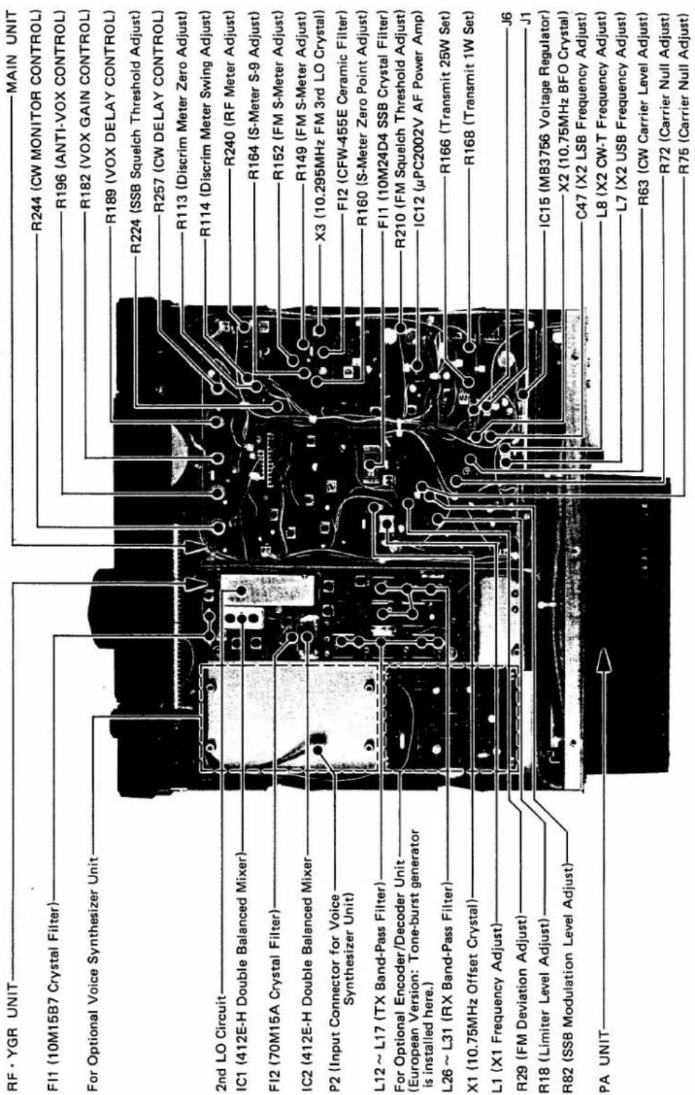
text_image
RF · YGR UNIT FI1 (10M15B7 Crystal Filter) For Optional Voice Synthesizer Unit 2nd LO Circuit IC1 (412E-H Double Balanced Mixer) FI2 (70M15A Crystal Filter) IC2 (412E-H Double Balanced Mixer) P2 (Input Connector for Voice Synthesizer Unit) L12 ~ L17 (TX Band-Pass Filter) For Optional Encoder/Decoder Unit (European Version: Tone-burst generator is installed here.) L26 ~ L31 (RX Band-Pass Filter) X1 (10.75MHz Offset Crystal) L1 (X1 Frequency Adjust) R29 (FM Deviation Adjust) R18 (Limiter Level Adjust) R82 (SSB Modulation Level Adjust) PA UNIT MAIN UNIT R244 (CW MONITOR CONTROL) R196 (ANTI-VOX CONTROL) R182 (VOX GAIN CONTROL) R189 (VOX DELAY CONTROL) R224 (SSB Squelch Threshold Adjust) R257 (CW DELAY CONTROL) R113 (Discrim Meter Zero Adjust) R114 (Discrim Meter Swing Adjust) R240 (RF Meter Adjust) R164 (S-Meter S-9 Adjust) R152 (FM S-Meter Adjust) R149 (FM S-Meter Adjust) X3 (10.295MHz FM 3rd LO Crystal) FI2 (CFW-455E Ceramic Filter) R160 (S-Meter Zero Point Adjust) FI1 (10M24D4 SSB Crystal Filter) R210 (FM Squelch Threshold Adjust) IC12 (μPC2002V AF Power Amp) R166 (Transmit 25W Set) R168 (Transmit 1W Set) J6 J1 IC15 (MB3756 Voltage Regulator) X2 (10.75MHz BFO Crystal) C47 (X2 LSB Frequency Adjust) L8 (X2 CW-T Frequency Adjust) L7 (X2 USB Frequency Adjust) R63 (CW Carrier Level Adjust) R72 (Carrier Null Adjust) R75 (Carrier Null Adjust)6 - 2 BOTTOM VIEW
text_image
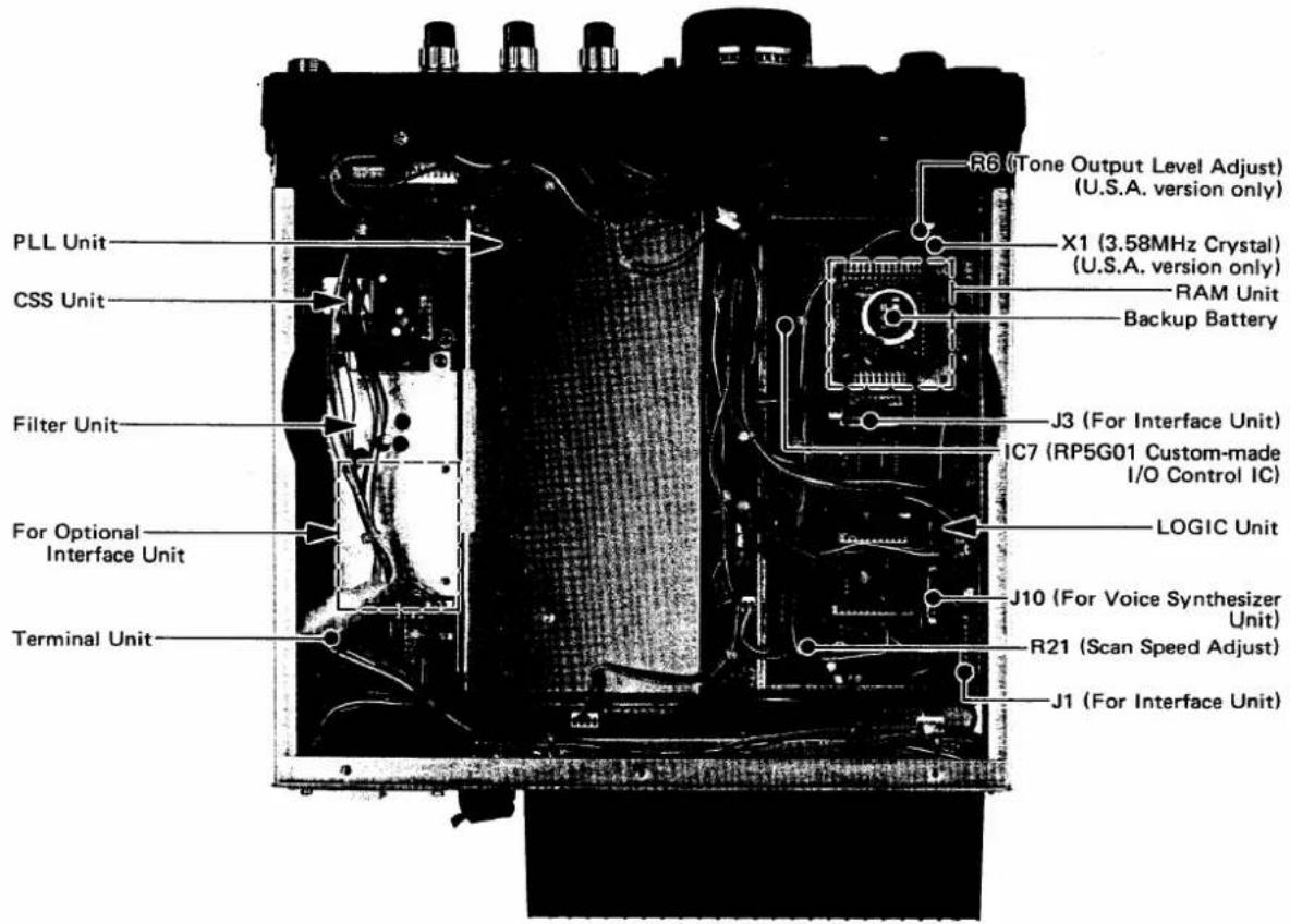
PLL Unit CSS Unit Filter Unit For Optional Interface Unit Terminal Unit R6 (Tone Output Level Adjust) (U.S.A. version only) X1 (3.58MHz Crystal) (U.S.A. version only) RAM Unit Backup Battery J3 (For Interface Unit) IC7 (RP5G01 Custom-made I/O Control IC) LOGIC Unit J10 (For Voice Synthesizer Unit) R21 (Scan Speed Adjust) J1 (For Interface Unit)6 - 3 PLL (HPL) UNIT (located under the LOGIC Unit)
text_image
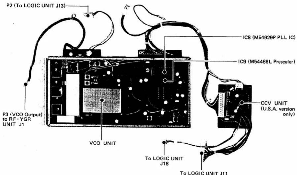
P2 (To LOGIC UNIT J13) IC8 (M54929P PLL IC) IC9 (M54466L Prescaler) CCV UNIT (U.S.A. version only) P3 (VCO Output) to RF·YGR UNIT J1 VCO UNIT To LOGIC UNIT J18 To LOGIC UNIT J11Before performing any work on the set, make sure that the power cord is detached from the transceiver.
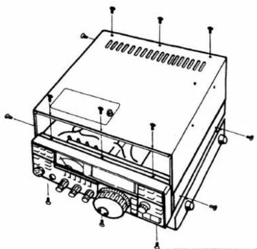
Remove the top and bottom covers by unscrewing the six screws each on the top and bottom, and the two screws on each side, while taking care not to damage the internal speaker, and unplug its connector.
natural_image
Technical line drawing of an electronic device with labeled components (no text or symbols present)7 - 1 BULIT-IN POWER SUPPLY UNIT IC-PS35
7-1-1 SPECIFICATIONS
| Number of Semiconductors | Transistor | 5 |
| IC | 2 | |
| Diode | 4 | |
| Input Voltage Allowable Voltage Fluctuation | 110/220V AC (50/60Hz) | |
| ±10% of input voltage (suitable line voltage) | ||
| Input Capacity Output Voltage Max. Load Current Dimentions Weight Kit Included | 550VA (at 20A load) | |
| 13.8V DC Negative ground | ||
| 20A (10 mins ON/10 mins OFF) | ||
| 194(W) x 56(H) x 186(D) mm | ||
| Approx. 2.3kg | ||
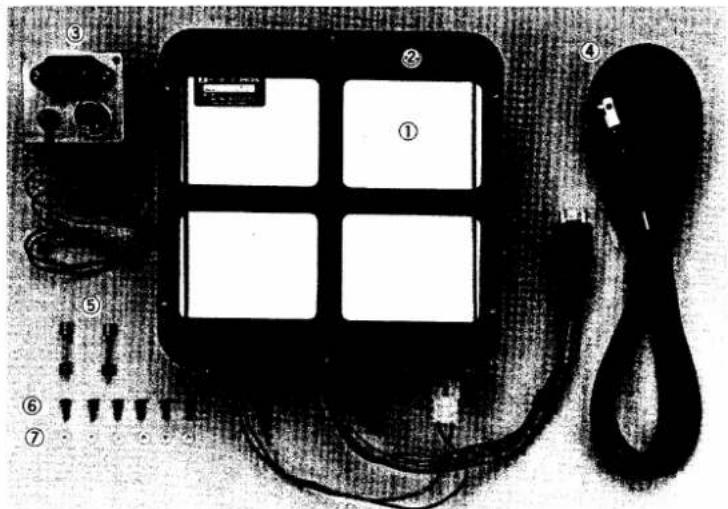
| 1 Main Unit | 1 | |
| 2 Insulation Spacer | 1 | |
| 3 Power Socket Unit | 1 | |
| 4 AC Power Cord | 1 | |
| 5 Spare Fuses | 2 | |
| 6 Installation Screws | 6 | |
| 7 Insulation Washers | 6 | |
text_image
Diagram of a telephone receiver with labeled components including buttons, cables, and connectors7-1-2 ASSEMBLY PROCEDURE
- Turn the transceiver upside down. Remove the "PLATE (A)" attached to the rear panel by unscrewing four screws. These screws will be used later.
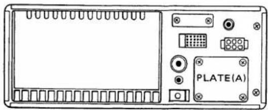
text_image
PLATE(A)- Attach the main unit (power supply) to the bottom cover with supplied screws and insulation washers. At
this time, insert the insulation spacer between the main unit and the bottom cover.
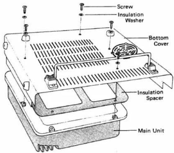
text_image
Screw Insulation Washer Bottom Cover Insulation Spacer Main Unit- Pass the DC power cable attached to P1 through the hole of the AC power socket plate as shown in the illustration, then insert the bushing into the hole.
Attach the AC power socket plate to the position which was attached the PLATE (A) before, by using the screws described in 1, so that the AC power socket is toward the bottom of the set.
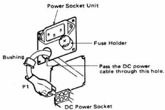
text_image
Power Socket Unit Fuse Holder Bushing Pass the DC power cable through this hole. P1 DC Power Socket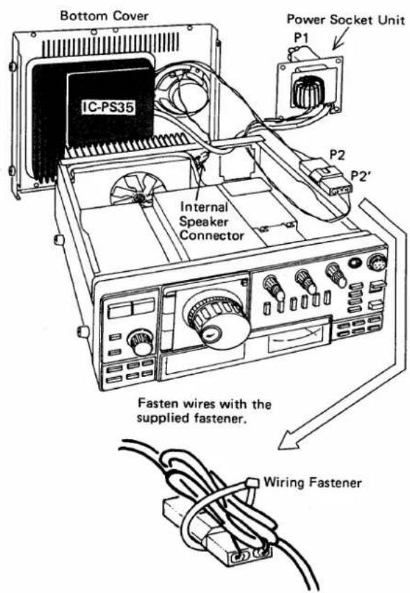
text_image
Bottom Cover IC-PS35 Power Socket Unit P1 P2 P2' Internal Speaker Connector Fasten wires with the supplied fastener. Wiring Fastener-
Pass the connector, P2', from the power socket unit to the inner chassis through the hole of the rear chassis. Then connect it with the connector, P2, from the main unit of the power supply.
-
Connect the internal speaker connector and replace the bottom and top covers of the set.
Plug P1 of the power supply unit to the DC Power Socket of the set.
7-1-3 OPERATION
- Connect the DC output plug, P1, of this unit into the transceiver DC power Socket securely. At this time, make sure that:
A. The power switch on the transceiver is OFF.
B. The T/R switch is in the RECEIVE position.
C. The PTT switch on the microphone is not depressed.
D. The VOX switch is in the OFF position.
- Connect the supplied AC power cord into the AC power socket (newly installed) on the rear panel of the transceiver.
Then connect the AC power plug into an AC power outlet.
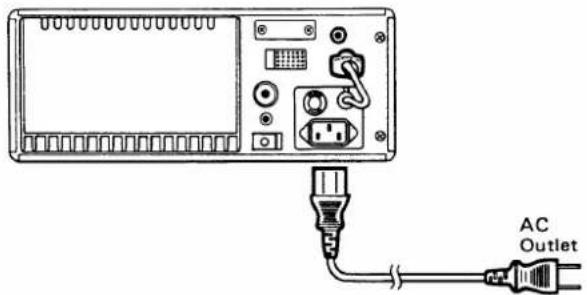
text_image
AC Outlet- By turning the transceiver power switch ON, this unit will be turned ON and supply a DC 13.8V to the transceiver.
7 - 1 - 4 CAUTION
- Ground the GROUND TERMINAL of the set with as short a wire as possible to prevent electrical shock, TVI, BCI and other problems.
- The power supply will shutdown when output voltage is shorted or consumed load current exceeds 25A. When the out voltage is stopped, turn the power switch of the transceiver OFF and remove the caused of the problem.
- If the fuse blows, replace it with a 10A (at 117V) or 5A (at 240V) fuse after checking the cause of the problem. Use a Philips (+) screwdriver to open the holder. The outside ring of the holder cannot be rotated.
7 - 2 VOICE SYNTHESIZER UNIT IC-EX310
7-2-1 ASSEMBLY PROCEDURE
- Insert 2-pin plug as shown in the photo into J2 of this unit, then install the unit with the supplied four screws as shown in the photo.
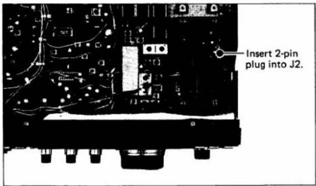
text_image
Insert 2-pin plug into J2.- Run the cord with 8-pin connector from the unit along the front panel, then pass it through the slot between the front panel and chassis located around the meter hood, to the bottom side.

text_image
Pass the cord to bottom side.- Turn the set upside down. Then insert the 8-pin connector into J10 of the LOGIC unit.
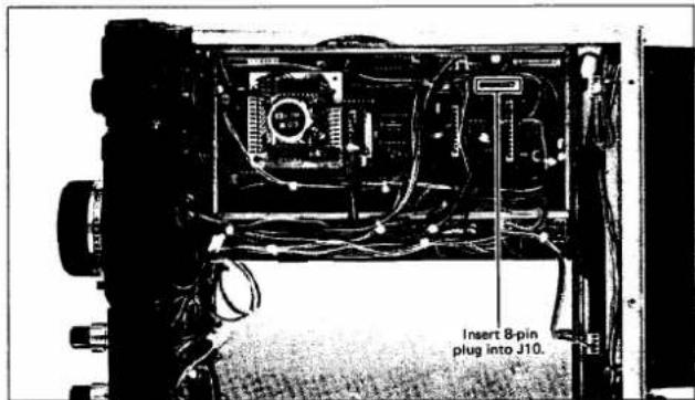
text_image
Insert 8-pin plug into J10.-
Adjust its volume and speaking speed if necessary. (Described later.)
-
Connect internal speaker connector, then replace the top and bottom covers of the set.
7-2-2 ADJUSTMENT
-
Adjust the volume of the speech and speaking speed before the top and bottom covers are replaced, if necessary.
-
Connect a power source and turn on the power switch.
-
By pushing the DIAL LOCK AND SPEECH switch, the unit is actuated and announces the displayed frequency in English.
-
The volume of the announcement is adjustable with R16 in the unit. Adjust it for a comfortable level.
-
By cutting W1 jumper wire, the speaking speed becomes faster.
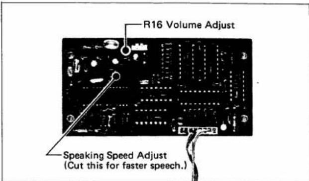
text_image
R16 Volume Adjust Speaking Speed Adjust (Cut this for faster speech.)- When finished with the adjustment, replace the top and bottom covers of the set.
7-2-3 HOW THE VOICE SYNTHSIZER UNIT WORKS
- When "435.280.0MHz" is displayed;
"FOUR THREE FIVE POINT TWO EIGHT ZERO ZERO MHz" will be heard.
- When a blanked memory channel is selected;
"POINT MHz" will be heard.
- When the TONE SELECT button is pushed and TONE NUMBER "16" is displayed;
"POINT ONE SIX MHz" will be heard.
- When the OFFSET WRITE button is pushed and offset frequency "05.000" is displayed;
"ZERO FIVE POINT ZERO ZERO ZERO MHz" will be heard.
SECTION 8 TROUBLESHOOTING
Your IC-471H has been carefully adjusted at the factory prior to shipping. The chart below has been provided to help you correct problems which are not equipment malfunctions. If you are unable to locate the trouble, or correct the fault, please contact your dealer or the nearest ICOM Service Center.
| Problem | Possible Cause | Solution |
| 1. Power does not come on when the switch is pushed. | Power cable is improperly connected.Power cord is connected with the polarity reversed.Blown fuse. | Carefully reconnect power cable.Disconnect the power cord, replace the blown fuse, then reconnect the power cord observing proper polarity.Check for the cause, then replace the fuse with a spare one.If using an IC-PS15 or IC-PS30, also check its fuse. |
| 2. No sound comes from the speaker. | AF GAIN control knob is completely counterclockwise.The unit is in the transmit mode, either by the T/R switch or the PTT switch on the microphone.The external speaker cable is connected to the unit but not to the external speaker.The internal speaker cable is not connected.A headphone is connected to the PHONES jack.The squelch is closed. | Turn the knob clockwise to a suitable level.Put the unit in the receive mode.Connect the cable to the speaker jack on the external speaker.Connect the speaker connection.Unplug the headphone.Adjust the squelch control. |
| 3. Sensitivity is low and only strong signals are audible. | RF GAIN control knob is turned counterclockwise.The antenna feed line is cut or shorted. | Turn the RF Gain control knob fully clockwise.Check the feed line and correct any improper condition. |
| 4. During receive, the "S" meter is higher than the "0" position even when there is no signal. | RF GAIN control knob is turned counterclockwise.The METER switch is pushed in (in FM mode). | Turn the knob fully clockwise.Push the METER switch and release it. |
| 5. Only incomprehensible voices are heard during SSB reception. | Receiving the wrong sideband.Receiving FM signals. | Set the sideband opposite the one you are using, either USB or LSB.Push the FM mode switch. |
| 6. No output power or low output power. | MIC GAIN setting is too low.When SSB is desired, but the MODE is in CW.PTT switch is not functioning due to improper connection of the mic connector.The antenna feed line is cut or shorted. | Turn the MIC GAIN control clockwise to the center (12 o'clock) position, or more.Set the MODE to SSB (USB or LSB).Check the connection of the MIC connector and correct any problems.Check the antenna feed line and correct any improper connection. |
| 7. The receive mode functions properly and your signals are transmitted, but you are unable to make contact with another station.(When desiring SIMPLEX mode.) (When desiring DUPLEX mode.) | The SPLIT switch is pushed in.The receive frequency is offset from the transmit frequency by the RIT control.The set is in the DUPLEX mode.The set is not in the DUPLEX mode.Improper offset frequency for the repeater. | Set the SPLIT switch to the out position.Turn OFF the RIT, or set the offset frequency to "0.0".Push the -DUP or +DUP button to clear the DUPLEX mode.Push the -DUP or +DUP button according to repeater input/output frequencies.Set the proper offset frequency according to the repeater input/output frequencies. |
| 8. The rear panel becomes hot. | The rear panel is for the heatsink of the PA module and may become as hot as 40°C (104°F) above room temperature. | Make sure the area around the unit has as much ventilation as possible. |
| 9. The frequency does not change by rotating the Tuning control. | DIAL LOCK is engaged.Improper setting of the DFS switch. | Disengage the DIAL LOCK by pressing and releasing the DIAL LOCK switch.Check the DFS switch whether pushed in or not and set it for proper operation. |
| 10. An abnormal out of band frequency is displayed on the frequency display. | The memory backup battery (graphite-lithium battery) on the RAM board is exhausted. | Contact with your dealer or ICOM service center. |
IC's IN TRANSMIT MODE
| UNIT | IC NO. | TRANSMIT | REMARKS | |||||||||||||||
| PIN NO. | ||||||||||||||||||
| 1 | 2 | 3 | 4 | 5 | 6 | 7 | 8 | 9 | 10 | 11 | 12 | 13 | 14 | 15 | 16 | |||
| MAIN | 1 | 4.0 | 4.0 | 4.0 | GND | 3.2 | 3.4 | 3.8 | 7.5 | ALL MODE | ||||||||
| MAIN | 2 | 1.4 | 1.4 | GND | 5.0 | 5.0 | FM | |||||||||||
| MAIN | 3 | 6.2 | 5.5 | 4.8 | GND | 2.7 | 2.7 | 2.7 | SSB | |||||||||
| MAIN | 4 | 0 | 0 | 0 | GND | 0.01 | 0 | 0.01 | NB ON SSB | |||||||||
| MAIN | 5 | 4.2 | 4.2 | 4.2 | GND | 2.8 | 2.9 | 7.0 | 7.8 | ALL MODE | ||||||||
| MAIN | 6 | 0 | 0 | 0 | 0 | 0 | 0 | 0 | GND | 0 | 0 | 0 | 0 | 0 | 0 | 0 | 0 | ALL MODE |
| MAIN | 7 | 0 | GND | 0 | ALL MODE | |||||||||||||
| MAIN | 8 | 0.1 | 0 | 0 | GND | 0.6 | 0 | 0.6 | FM | |||||||||
| MAIN | 9 | 0 | 0 | 0 | -9.5 | 0 | 0 | 0 | -0.1 | SSB | ||||||||
| MAIN | 10 | 7.4 | 0 | 0 | -9.5 | 4.0 | 4.0 | -2.3 | 8.0 | ALL MODE | ||||||||
| MAIN | 11 | 4.8 | 3.8 | 3.5 | GND | 3.5 | 3.4 | 5.6 | 6.2 | USB LSB | ||||||||
| MAIN | 12 | 0.3 | 0.7 | GND | 6.0 | 13.0 | ALL MODE | |||||||||||
| MAIN | 13 | 1.1 | 5.2 | 4.6 | GND | 8.6 | 2.6 | 0 | 1.1 | 5.2 | 4.2 | 0 | 8.6 | 0.6 | 0 | ALL MODE | ||
| MAIN | 14 | 0.3 | 0 | 0.6 | 0.6 | 0 | 0 | 0 | 0.6 | 1.7 | 0 | 0 | 0 | 0 | 0 | GND | 0.2 | FM |
| MAIN | 15 | 8.0 | 13.0 | 8.0 | GND | 1.2 | 0.6 | 0 | 8.0 | ALL MODE | ||||||||
| CSS | 1 | 2.9 | 2.7 | 2.4 | GND | 2.7 | 3.0 | 7.1 | 7.8 | SSB SQL OPEN | ||||||||
| PA | 1 | 0.01 | 9.0 | 13.8 | 13.8 | 3.4 | GND | SSB | ||||||||||
| DC-DC | 1 | 13.0 | GND | -9.5 | ||||||||||||||
IC's IN RECEIVE MODE
| UNIT | IC NO. | RECEIVE | REMARKS | |||||||||||||||
| PIN NO. | ||||||||||||||||||
| 1 | 2 | 3 | 4 | 5 | 6 | 7 | 8 | 9 | 10 | 11 | 12 | 13 | 14 | 15 | 16 | |||
| MAIN | 1 | 4.0 | 4.0 | 4.0 | GND | 3.2 | 3.4 | 3.8 | 7.4 | ALL MODE | ||||||||
| MAIN | 2 | 0.7 | 0.7 | GND | 0.7 | 0.7 | FM | |||||||||||
| MAIN | 3 | 6.2 | 5.5 | 4.8 | GND | 2.7 | 2.7 | 2.7 | SSB | |||||||||
| MAIN | 4 | 5.0 | 1.7 | 1.9 | GND | 6.7 | 2.9 | 6.7 | NB ON SSB | |||||||||
| MAIN | 5 | 4.2 | 4.2 | 4.2 | GND | 2.8 | 3.0 | 4.6 | 7.8 | ALL MODE | ||||||||
| MAIN | 6 | 4.6 | 4.8 | 4.8 | 3.5 | 3.4 | 1.7 | 0.6 | GND | 1.6 | 1.1 | 1.7 | 0.1 | 0.1 | 1.7 | 1.4 | 4.8 | ALL MODE |
| MAIN | 7 | 7.0 | GND | 4.8 | ALL MODE | |||||||||||||
| MAIN | 8 | 3.0 | 1.0 | 1.0 | GND | 3.8 | 1.5 | 3.8 | FM | |||||||||
| MAIN | 9 | 0.9 | 0.4 | 0.4 | -9.5 | 0.6 | 0.6 | 0.4 | 6.5 | SSB | ||||||||
| MAIN | 10 | 7.4 | 0 | 0 | -9.5 | 4.0 | 4.0 | -2.3 | 8.0 | ALL MODE | ||||||||
| MAIN | 11 | 4.8 | 3.8 | 3.5 | GND | 3.5 | 3.4 | 5.6 | 6.2 | USB LSB | ||||||||
| MAIN | 12 | 0.3 | 0.7 | GND | 6.0 | 13.0 | ALL MODE | |||||||||||
| MAIN | 13 | 1.1 | 5.2 | 4.6 | GND | 8.5 | 2.6 | 0 | 1.1 | 5.2 | 4.2 | 0 | 8.5 | 1.1 | 0 | FM | ||
| MAIN | 14 | 5.5 | 5.2 | 4.9 | 5.7 | 0.7 | 0.9 | 1.0 | 5.7 | 3.1 | 2.0 | 2.0 | 0 | 5.2 | 0 | GND | 2.0 | FM |
| MAIN | 15 | 8.0 | 13.0 | 8.0 | GND | 1.7 | 8.0 | 0 | 0.7 | ALL MODE | ||||||||
| CSS | 1 | 2.9 | 2.7 | 2.4 | GND | 2.7 | 3.0 | 7.1 | 7.8 | SSB SQL OPEN | ||||||||
| DC-DC | 1 | 13.0 | GND | -9.5 | ||||||||||||||
| PA | 1 | 0 | 0.13 | 13.8 | 13.8 | 0.08 | GND | |||||||||||
TRANSISTORS
| UNIT | TRANSMIT | RECEIVE | REMARKS | |||||||
| Q NO. | BASE OR GATE1 | GATE2 | COLLECTOR OR DRAIN | EMITTER OR SOURCE | BASE OR GATE1 | GATE2 | COLLECTOR OR DRAIN | EMITTER OR SOURCE | ||
| MAIN | 1 | 4.3 | 7.0 | 3.9 | 0.025 | 0.115 | 0 | ALL MODE | ||
| MAIN | 2 | 7.6 | 7.9 | 7.0 | 1.33 | 0.66 | 0.66 | FM | ||
| MAIN | 3 | 3.6 | 7.0 | 3.0 | 0.17 | 0.66 | 0 | FM | ||
| MAIN | 4 | -0.45 | 3.2 | 7.0 | 0.35 | -0.45 | 0 | 0.06 | 0.05 | FM |
| MAIN | 5 | 0.01 | 5.2 | GND | 0.68 | 0.04 | GND | CW | ||
| MAIN | 6 | 3.2 | 6.6 | 3.0 | 3.2 | 6.6 | 3.0 | SSB | ||
| MAIN | 7 | 3.0 | 6.6 | 3.0 | 3.0 | 6.6 | 3.0 | SSB | ||
| MAIN | 8 | 0 | 3.7 | GND | 0.7 | 0 | GND | USB | ||
| MAIN | 9 | 3.7 | 6.8 | 3.1 | 0 | 0 | 0 | USB | ||
| MAIN | 10 | 2.4 | 6.2 | 1.7 | 0 | 0.05 | 0 | USB | ||
| MAIN | 11 | 0 | 0 | 0 | 5.0 | 0 | 4.8 | SSB | ||
| MAIN | 12 | 0 | 2.4 | 0 | GND | 0 | 2.6 | 5.2 | GND | ALL MODE |
| MAIN | 13 | 0.6 | 0 | GND | 0.6 | 0 | GND | FM METER SW OFF | ||
| MAIN | 14 | 4.0 | 4.0 | 3.7 | 4.3 | 4.3 | 4.0 | FM | ||
| MAIN | 15 | 4.0 | 3.7 | 3.7 | 4.3 | 4.1 | 4.1 | FM | ||
| MAIN | 16 | -8.1 | 1.0 | -8.8 | -8.2 | 1.1 | -8.8 | FM | ||
| MAIN | 17 | 0 | -0.08 | 0 | 0.92 | 6.4 | 1.5 | SSB | ||
| MAIN | 18 | 0 | 2.6 | 0 | 0 | 0 | 2.8 | 6.3 | 0.66 | SSB |
| MAIN | 19 | 0 | 2.6 | 0 | GND | 0 | 2.8 | 6.0 | GND | SSB |
| MAIN | 20 | 0 | 0 | GND | 0 | 4.0 | GND | SSB | ||
| MAIN | 21 | 0 | 0 | GND | 0.03 | 1.85 | GND | SSB NB ON | ||
| MAIN | 22 | 1.35 | 0.63 | 0.63 | 6.4 | 8.0 | 5.8 | FM | ||
| MAIN | 23 | 0.6 | 0 | GND | 0.6 | 0 | GND | FM METER SW ON | ||
| MAIN | 24 | 0 | 0 | GND | 0 | 1.0 | GND | FM | ||
| MAIN | 25 | 0 | 7.0 | 0 | 7.2 | 7.0 | 6.5 | SSB | ||
| MAIN | 26 | 0.6 | 0 | GND | 0.6 | 0 | GND | FM METER SW OFF | ||
| MAIN | 27 | 6.5 | 0 | 7.0 | 6.5 | 0 | 7.0 | USB LSB VOX ON | ||
| MAIN | 28 | 6.5 | 0 | 7.0 | 6.5 | 0 | 7.0 | USB LSB VOX ON | ||
| MAIN | 29 | 0 | 0 | GND | 0 | 0 | GND | USB LSB VOX ON | ||
| MAIN | 30 | 1.3 | 4.8 | 0.95 | 1.3 | 4.8 | 0.95 | ALL MODE | ||
| MAIN | 31 | 0.65 | 0 | GND | 0.07 | 5.2 | GND | FM SQL OPEN | ||
| MAIN | 32 | 0.6 | 0.05 | GND | 0.6 | 0 | GND | CW | ||
| MAIN | 33 | 0.6 | 0 | 0 | 4.6 | 4.1 | 13.8 | ALL MODE | ||
| MAIN | 34 | 1.2 | 5.3 | 0.65 | 1.2 | 5.3 | 0.65 | CW KEY DOWN | ||
| MAIN | 35 | 0 | 0 | GND | 0 | 0 | GND | CW KEY DOWN | ||
| MAIN | 36 | 7.1 | 7.9 | 7.9 | 7.1 | 7.9 | 7.9 | CW KEY DOWN | ||
| MAIN | 37 | 0.65 | 0 | 0 | 0.65 | 0 | 0 | CW KEY DOWN | ||
| MAIN | 38 | 0 | 0 | 0 | 0 | 0 | 0 | USB LSB VOX ON | ||
| MAIN | 39 | 0 | 0 | GND | 0 | 13.0 | GND | USB LSB VOX ON | ||
| MAIN | 40 | 0 | 0 | 0 | 0 | 0 | 0 | USB LSB VOX ON | ||
| MAIN | 41 | 0 | 0 | GND | 0 | 0 | GND | USB LSB VOX ON | ||
| MAIN | 42 | 0.65 | 0 | GND | 0.01 | 5.4 | GND | SSB SQL OPEN | ||
| RF-YGR | 1 | GND | 0.07 | 0.05 | GND | 6.7 | 1.25 | FM | ||
| RF-YGR | 2 | 2.65 | 7.4 | 2.15 | 2.65 | 7.4 | 2.15 | FM | ||
| RF-YGR | 3 | 1.05 | 7.0 | 0.65 | 1.05 | 7.0 | 0.65 | FM | ||
| RF-YGR | 4 | 0.75 | 5.8 | GND | 0.03 | 0.14 | GND | FM | ||
| RF-YGR | 5 | 0.75 | 5.6 | GND | 0.03 | 0.13 | GND | FM | ||
| RF-YGR | 6 | 0 | 3.5 | 7.8 | GND | 0 | 0.01 | 0.11 | GND | FM |
| RF-YGR | 7 | 0.75 | 5.4 | GND | 0.03 | 0.15 | GND | FM | ||
| RF-YGR | 8 | 0.75 | 5.8 | GND | 0.03 | 0.15 | GND | FM | ||
| RF-YGR | 9 | 0.75 | 6.0 | GND | 0.03 | 0.15 | GND | FM | ||
| RF-YGR | 10 | 0 | 2.6 | 0.08 | GND | 0 | 2.6 | 7.7 | GND | FM |
| RF-YGR | 11 | GND | 0.07 | 0.05 | GND | 6.7 | 1.25 | FM | ||
| RF-YGR | 12 | 0 | 0 | 0.1 | GND | 0 | 0 | 7.9 | GND | FM |
| UNIT | Q NO. | TRANSMIT | RECEIVE | EMITTER OR SOURCE | REMARKS | |||||
| BASE OR GATE1 | GATE2 | COLLECTOR OR DRAIN | EMITTER OR SOURCE | BASE OR GATE1 | GATE2 | COLLECTOR OR DRAIN | ||||
| PA | 1 | 0.7 | 13.8 | GND | 0 | 13.8 | GND | SSB | ||
| PA | 2 | 0.7 | 13.8 | GND | 0 | 13.8 | GND | SSB | ||
| PA | 3 | 1.3 | 13.8 | 0.7 | 0 | 13.8 | 0 | SSB | ||
| PA | 4 | 9.7 | 13.5 | 9.0 | 0 | 13.8 | 0 | SSB | ||
| PA | 5 | 0.15 | 9.7 | GND | 0.8 | 0 | GND | SSB | ||
| PA | 6 | 8.2 | 0.15 | GND | 0 | 0.8 | GND | SSB | ||
ACCESSORY (ACC) SOCKET CONNECTION
Various functions are available through the accessory socket such as modulation output, receiver output, T/R change-over, and so forth. The table below shows those terminals.
ACC SOCKET CONNECTIONS
Outside view
| PIN No. | FUNCTION |
| 1. | Output from the squelch control stage. (+8V when the squelch is ON) |
| 2. | 13.8 Volts DC in conjunction with the power switch operation. |
| 3. | Connected to Push-to-talk, T/R change-over switch. When grounded, the set operates in the transmit mode. |
| 4. | Output from the receive detector stage. Fixed output regardless of AF output or AF gain. |
| 5. | Output from Transmitter MIC amplifier stage. (Input for MIC gain control stage.) |
| 6. | 8 Volts DC available when transmitting. (relay can not be directly actuated. Max. 5mA). |
| 7. | Input for external ALC voltage. |
| 8. | Ground |
| 9. | NC (No Connection) |
| 10. | Output of a voltage applied to the meter. |
| 11. | NC |
| 12. | Input for external Noise Blanker control voltage. |
| 13. | Input for external FM squelch control voltage. |
| 14. | Input for external SSB squelch control voltage. |
| 15.~24. | NC |
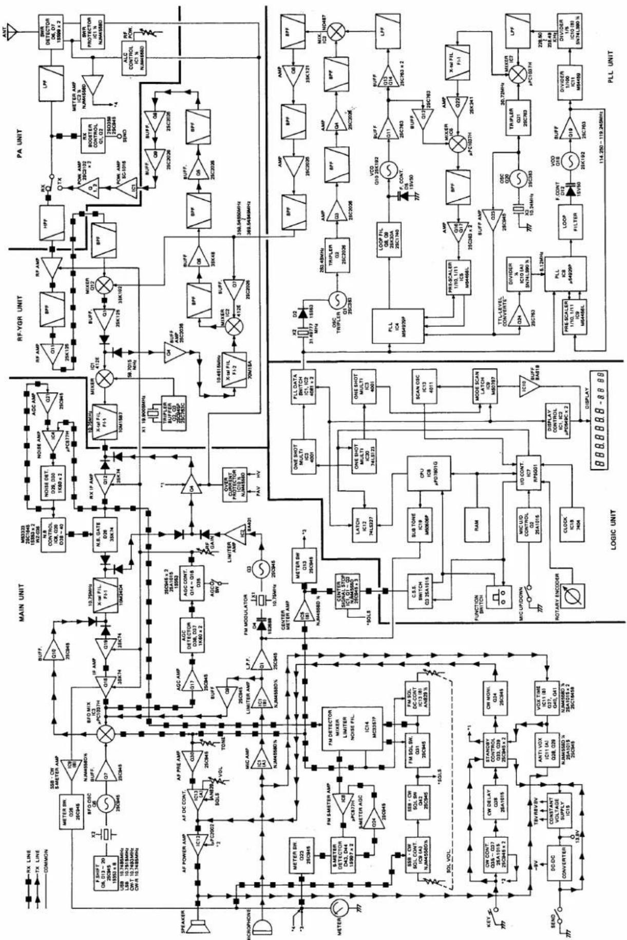
flowchart
graph TD
    subgraph Speaker
        A["Speaker"] --> B["Microphone"]
        C["Microcontroller"] --> D["METER"]
        D --> E["KEY"]
        E --> F["SAND"]
        F --> G["CONVERTER"]
        G --> H["SWR CONT"]
        H --> I["STANDARD CONTROL"]
        I --> J["ON MOHL"]
        J --> K["VOX TIME"]
        K --> L["CLOCK IC18 7404"]
        L --> M["FUNCTION SWITCH"]
        M --> N["MIC UP/DOWN"]
        N --> O["ROTARY ENCODER"]
        O --> P["LOGIC UNIT"]
        Q["RF-YGR UNIT"] --> R["PA UNIT"]
        S["MINI"] --> T["SWR PROTECTOR"]
    end

    subgraph Microcontroller
        U["Speaker"] --> V["METER SW"]
        V --> W["SAND"]
        W --> X["SWR CONT"]
        X --> Y["STANDARD CONTROL"]
        Y --> Z["ON MOHL"]
        Z --> AA["CLOCK IC18 7404"]
        AA --> AB["FUNCTION SWITCH"]
        AB --> AC["MIC UP/DOWN"]
        AC --> AD["ROTARY ENCODER"]
        AD --> AE["CLOCK IC18 7404"]
        AE --> AF["LOGIC UNIT"]
        AG["RF-YGR UNIT"] --> AH["PA UNIT"]
        AI["MINI"] --> AJ["SAND"]
        AJ --> AK["SWR PROTECTOR"]

    subgraph Logic Unit
        AL["LOGIC UNIT"] --> AM["PLL UNIT"]

    subgraph PLL Unit
        AN["MINI"] --> AO["SAND"]
        AP["SWR CONT"] --> AQ["SAND"]
    end

    style Speaker fill:#f9f,stroke:#333
    style Microcontroller fill:#ccf,stroke:#333
    style Logic Unit fill:#cfc,stroke:#333
    style PLL Unit fill:#fcc,stroke:#333
text_image
ICOMICOM INCORPORATED
1-6-19, KAMI KURATSUKURI, HIRANO-KU, OSAKA JAPAN