
MP9500 - Tastatur KAWAI - Kostenlose Bedienungsanleitung
Finden Sie kostenlos die Bedienungsanleitung des Geräts MP9500 KAWAI als PDF.


| Marke | Kawai |
| Modell | MP9500 |
| Kategorie | Stage Piano / Tastatur |
| Anzahl der Tasten | 88 (Holztastatur mit Hammermechanik) |
| Polyphonie | Maximal 64 Stimmen |
| Interne Klänge | 64 hochwertige Klänge |
| Effekte | 7 Hallarten, 21 Effekte, 4-Band-Equalizer |
| Anzahl der Zonen | 4 (einstellbar als Int, Ext oder Both) |
| Speicher | 64 MULTI- und 64 SINGLE-Programme |
| Display | 16 x 2 LCD mit Hintergrundbeleuchtung |
| Anschlüsse | 1/4" Out (L/MONO, R), XLR Out (L, R), Kopfhörer, MIDI In/Out/Thru, Damper/Soft Pedal, FSW, EXP, AC Inlet |
| MIDI | In/Out/Thru, 16 Kanäle, CC- und SysEx-Unterstützung |
| Regler | 4 Multifunktions-Drehregler, 4 Fader, Pitch- und Modulationsrad |
| Pedale | Damper/Soft-Pedal (Kawai F-2r) im Lieferumfang, optionaler Fußschalter, Expression-Pedal |
| Abmessungen (B x T x H) | 1466 x 442 x 189 mm |
| Gewicht | 32 kg |
| Stromversorgung | Netzkabel (im Lieferumfang), geerdeter Stecker |
| Leistungsaufnahme | Nicht angegeben, jedoch Standard für Stage Pianos (ca. 30-50 W) |
| Lieferumfang | Notenständer, Netzkabel, Damper/Soft-Pedal (F-2r), Bedienungsanleitung |
| Zubehör (optional) | Fußschalter (Kawai F-1), Expression-Pedal |
| Reinigung | Mit einem weichen, leicht feuchten Tuch abwischen; keine Lösungsmittel |
| Betriebstemperatur | Nicht angegeben, jedoch Vermeidung von extremen Temperaturen und Feuchtigkeit empfohlen |
Häufig gestellte Fragen - MP9500 KAWAI
Benutzerfragen zu MP9500 KAWAI
0 Frage zu diesem Gerät. Beantworten Sie die, die Sie kennen, oder stellen Sie Ihre eigene.
Eine neue Frage zu diesem Gerät stellen
Laden Sie die Anleitung für Ihr Tastatur kostenlos im PDF-Format! Finden Sie Ihr Handbuch MP9500 - KAWAI und nehmen Sie Ihr elektronisches Gerät wieder in die Hand. Auf dieser Seite sind alle Dokumente veröffentlicht, die für die Verwendung Ihres Geräts notwendig sind. MP9500 von der Marke KAWAI.
BEDIENUNGSANLEITUNG MP9500 KAWAI
KAWAI
Professional Stage Piano
MP9500
Owner's Manual
Important Safety Instructions
SAVE THESE INSTRUCTIONS
INSTRUCTIONS PERTAINING TO A RISK OF FIRE, ELECTRIC SHOCK, OR INJURY TO PERSONS

CAUTION
RISK OF ELECTRIC SHOCK DO NOT OPEN

WARNING
TO REDUCE THE RISK OF FIRE OR ELECTRIC SHOCK, DO NOT EXPOSE THIS PRODUCT TO RAIN OR MOISTURE.
AVIS : RISQUE DE CHOC ELECTRIQUE - NE PAS OUVRIR.
TO REDUCE THE RISK OF ELECTRIC SHOCK, DO NOT REMOVE COVER (OR BACK). NO USER-SERVICEABLE PARTS INSIDE. REFER SERVICING TO QUALIFIED SERVICE PERSONNEL.

The lighting flash with arrowhead symbol, within an equilateral triangle, is intended to alert the user to the presence of uninsulated "dangerous voltage" within the product's enclosure that may be of sufficient magnitude to constitute a risk of electric shock to persons.

The exclamation point within an equilateral triangle is intended to alert the user to the presence of important operating and maintenance (servicing) instructions in the literature accompanying the product.
WARNING - When using electric products, basic precautions should always be followed, including the following:
Read all the instructions before using the product.
To reduce the risk of injury, close supervision is necessary when a product is used near children.
Do not use this product near water - for example, near a bathtub, washbowl, kitchen sink, in a wet basement, or near a swimming pool, or the like.
Do not touch the power plug with wet hands. There is a risk of electrical shock. Treat the power cord with care as well. Stepping on or tripping over it can break or short-circuit the wire inside.

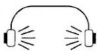
This product in combination with an amplifier and headphones or speakers, may be capable or producing sound level that could cause permanent hearing loss. Do not operate for a long period of time at a high volume level or at a level that is uncomfortable. If you experience any hearing loss or ringing in the ear, you should consult an audiologist.
The product should be located so that its location or position does not interfere with its proper ventilation.
The product should be located away from heat sources such as radiators, heat registers, or other products that produce heat.
Keep the instrument away from electrical motors, neon signs, fluorescent light fixture, and other sources of electrical noises.

The product should be connected to a power supply only of the type described in the operating instructions or as marked on the product.


Always turn the power off when the instrument is not in use. The power supply cord of the product should be unplugged from the outlet when left unused for a long period of time.

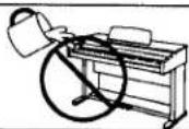
Care should be taken so that objects do not fall and liquids are not spilled into the enclosure through openings.
The product should be serviced by qualified service personnel when:
● The power supply cord or the plug has been damaged.
- Objects have fallen, or liquid has been spilled into the product.
● The product has been exposed to rain.
● The product does not appear to operate normally or exhibits a marked change in performance.
● The product has been dropped, or the enclosure damaged.
Do not attempt to service the product beyond that described in the user-maintenance instructions. All other servicing should be referred to qualified service personnel.

When disconnecting the AC power cord's plug, always hold the plug and pull it to remove it.


Pulling the AC power cord itself may damage the cord, causing a fire, electric shock or short-circuit.
Do not use the product in the following areas.
● Areas, such as those near windows, where the product is exposed to direct sunlight
● Extremely cold areas, such as outside
● Extremely humid areas
● Areas where a large amount of sand or dust is present
● Areas where the product is exposed to excessive vibrations
Using the product in such areas may result in product breakdown.
Do not wipe the product with benzene or thinner.

Doing so may result in discoloration or deformation of the product.
When cleaning the product, put a soft cloth in lukewarm water, squeeze it well, then wipe the product.
Do not stand on the product or exert excessive force.

Doing so may cause the product to become deformed or fall over, resulting in breakdown or injury.
Take care not to drop the product.
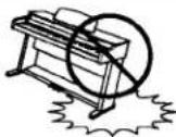
Please note that the product is heavy and must be carried by more than two persons. Dropping the product may result in breakdown.
Do not lean against the keyboard.
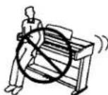
Doing so may cause the product to fall over, resulting in injury.
When connecting the AC power cord and other cords, take care not to get them tangled.

Failure to do so may damage them, resulting in fire, electric shock or short-circuit.
Before connecting cords, make sure that the power to this product and other devices is turned OFF.
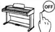
Failure to do so may cause breakdown of this product and other devices.
GROUNDING INSTRUCTIONS
This product must be grounded. If it should malfunction or breakdown, grounding provides a path of least resistance for electric current to reduce the risk of electric shock. This product is equipped with a cord having an equipment-grounding conductor and a grounding plug. The plug must be plugged into an appropriate outlet that is properly installed and grounded in accordance with all local codes and ordinances.
DANGER - Improper connection of the equipment-grounding conductor can result in a risk of electric shock. Check with a qualified electrician or serviceman if you are in doubt as to whether the product is properly grounded. Do not modify the plug provided with the product - if it will not fit the outlet, have a proper outlet installed by a qualified electrician.
Notes on Repair
Should an abnormality occur in the product, immediately turn the power OFF, disconnect the power cord plug, and then contact the shop from which the product was purchased.
FCC Information
This equipment has been tested and found to comply with the limits for a Class B digital device, pursuant to Part 15 of the FCC Rules. These limits are designed to provide reasonable protection against harmful interference in a residential installation. This equipment generates, uses and can radiate radio frequency energy and, if not installed and used in accordance with the instructions, may cause harmful interference to radio communications. If this equipment does cause harmful interference to radio or television reception, which can be determined by turning the equipment off and on, the user is encouraged to try to correct the interference by one or more of the following measures:
-Reorient or relocate the receiving antenna.
-Increase the separation between the equipment and receiver.
-Connect the equipment into an outlet on a different electrical circuit from the receiver.
-Consult the dealer or an experienced radio/TV technician for help.
Canadian Radio Interference Regulations
This instrument complies with the limits for a class B digital apparatus, pursuant to the Radio Interference Regulations, C.R.C., c. 1374.
TABLE OF CONTENTS
WELCOME TO THE MP9500....6
-
NAMES AND FUNCTIONS....8
-
SINGLE mode....12
1) Getting Ready....12
2) Playing the MP9500 as a stand anole Digital Piano....12
3) Using the MP9500 as a MIDI controller.....13
4) SINGLE Edit....14
Voicing....15
Tx/Rx Ch (Transmit/Receive Channel).....15
FootSW (Foot Switch).....15
ExpPdl (Expression Pedal).....15
5) TRANSPOSE.....16
6) EFX/REVERB....16
EFX....16
EFX ON/OFF.....16
EFX type.....17
REVERB....18
REVERB ON/OFF....18
REV type.....18
Adjusting the EFX/REVERB value using the CONTROL KNOBS.....19
7) EQ (EQUALIZER)....20
8) TONE MODIFY.....21
9) Transmitting MIDI Control Changes using the CONTROL KNOBS.....22
- MULTI mode.....23
1) MULTI Recall.....23
2) MULTI Edit....24
Edit Common....25
Edit Zone....25
How to change the MULTI Edit parameters.....24
Zone Mode....25
Zone Mode (Edit)....25
Sound
TX Prg #
Prg #
TX Bank
Bank MSB/LSB
TX Ch
K.Range Hi/Lo
Vel SW (Velocity Switch)
Vel SW Val (Velocity Switch Value)
Vel Sense (Velocity Sense)
Transpose
TX Volume (Transmitting Volume)
Volume
Damper
FootSW
ExpPedal
Modulation
Bender
TXBendrRng (Transmitting Bender Range)
Bender Range
TX Pan (Transmitting Pan)
Pan
TX Fine Tune (Transmitting Fine Tune)
Fine Tune
TX Knob [A-D]
Knob [A-D] CC# (Knob A-D/Control Change No.)
TX Cutoff (Transmitting Cutoff)
TX Attack (Transmitting Attack)
TX Decay (Transmitting Decay)
TX Release (Transmitting Release)
Voicing
Solo
Solo Mode
- STORE.....33
1) Store SINGLE.....33
2) Store MULTI.....34
3) Dump All.....36
4) Dump Current....37
5) Reset Current.....38
6) Reset All.....39
- LINK.....40
1) LINK setting.....40
2) Store LINK....41
- SYSTEM mode.....42
1) System Menu.....42
How to change the SYSTEM Edit parameters....42
System Ch (System Channel)....43
Touch ....43
Temperament....44
Key of Temperament....44
Tuning C \~ B.....45
SysTune (System Tuning)....45
FootSW CC# (Footswitch Control Change),....45
ExpPdl CC# (Expression Pedal Control Change)....45
Local Control....45
RX Ch [1-16] (Receive Channel)....46
LCD Contrast....46
- OTHERS.....47
MIDI IN....47
MULTI Program Number Table.....47
SINGLE Program Number List.....48
Specifications....49
MP9500 MIDI Implementation.....50
Thank you for purchasing the KAWAI MP9500. The MP9500 Professional Stage Piano features 64 Internal Sounds of the highest quality. The MP9500 can also be used as a MIDI master controller. On stage, at home, or in the studio, the MP9500 has been designed to offer quick and easy access to many sophisticated features.
BASIC FEATURES of the MP9500
SINGLE mode & MULTI mode & SYSTEM mode

The MP9500 operates in three modes: the SINGLE mode, the MULTI mode and the SYSTEM mode. The SINGLE mode provides instant access to the Internal Sounds, Reverb, EFX, and other Real Time Controls. The MULTI mode is used to both program and recall any of the 64 User settings such as Layer and Split. The SYSTEM mode is used to access global settings of the MP9500.
4 ASSIGNABLE ZONES
The MP9500 has 4 zones which can be set to INT, EXT or BOTH individually. INT (Internal) is to play any of the 64 internal sounds. EXT (External) is to play external MIDI devices. BOTH is to play internal sound and external MIDI devices at the same time. Each zone can be played individually, or multiple zones can be freely split, layered and velocity switched to create stunning and personalized performances.
ACOUSTIC TOUCH KEYBOARD
The MP9500 has a wood constructed keyboard with an advanced hammer action.
REVERB AND EFFECTS
The MP9500 offers 7 high quality REVERB types, and 21 different effect types.
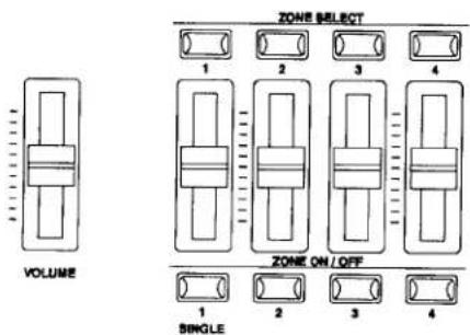
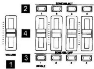
ZONE SELECT buttons
The button for the selected zone will be lit. Only one zone can be edited at a time.
Fader
Use these faders to adjust the volume level for each zone.
ON/OFF buttons
Use these buttons to turn each zone On or Off.
MULTI & LINK
The MP9500 has memory for 64 MULTI settings for various performance situations. In addition, up to 32 SINGLE or MULTI patches can be chained together in any order for instant access using the LINK Mode.
![graph TD A["MULTI 5-6"] --> B["MULTI 1-3"] B --> C["MULTI 1-2"] C --> D["MULTI 1-1"] D --> E["TRANSPOSE"] E --> F["FADERS"] F --> G["SELECT"] F --> H["ON/OFF"] D --> I["CONTROL KNOBS"] I --> J["EFFECT"] I --> K["EQ"] I --> L["TONE MODIFY"] I --> M["MIDI"] D --> N["MENU"] N --> O["Edit Program"] N --…](/content/2026/05/777432/images/af188d99edbc4bbe10f0c81d04b62e346b60ed30279b2285780252796c750fb6.jpg)
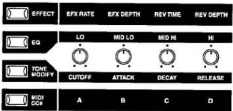
CONTROL KNOBS
The MP9500 has 4 multi-function CONTROL KNOBS, which offer real time control of the EFFECTS, EQ. TONE MODIFY and MIDI CONTROL. CHANGE messages.
1. NAMES AND FUNCTIONS
FRONT PANEL
[FADER SECTION]
- VOLUME Fader
The VOLUME fader controls the master volume level of the MP9500. (Note: The VOLUME fader does not affect the Fixed Outputs on the rear panel.)
- ZONE SELECT buttons
The ZONE SELECT buttons are used to select one of the four zones for editing. Only one zone can be selected at a time. The front panel setting represents the current zone status.
- ON/OFF buttons
The ON/OFF buttons are used to turn zones ON/OFF. When the button is lit, the zone is active.
- FADERS (zone volume level control)
Each fader controls the volume level of a designated zone. When multiple zones are active, these faders can be used as an audio mixer.
[CONTROL KNOBS SECTION]
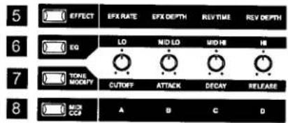
The four CONTROL KNOBS are multi-function real time controllers. The different functions can be selected using the four buttons to the left side of the CONTROL KNOBS. When a function button is lit, that function is active. Touching any of these knobs will instantly change the Display to the current knob function and value.
- EFFECT button
When this button is lit, the CONTROL KNOBS will adjust the REVERB time, REVERB depth, EFX rate and EFX depth.
- EQ button
When this button is lit, the CONTROL KNOBS will adjust the 4 band graphic equalizer.
- TONE MODIFY button
When this button is lit, the CONTROL KNOBS will adjust the CUTOFF, ATTACK, DECAY and RELEASE Levels for the selected zone.
- MIDI CC# button
When this button is lit, MIDI control changes are sent from the MP9500 to the MIDI device specified by the selected zone.
[WHEEL CONTROLLERS]
- PITCH BEND
This control wheel smoothly bends the pitch Up or Down from its current value.
- MODULATION
This control wheel controls the modulation (vibrato) depth. Moving the wheel forward increases the vibrato depth.
![KAWAI MP9500 - [WHEEL CONTROLLERS] - 1](/content/2026/05/777432/images/397746a14d342bb95366dc0b43956dbaa7173f16069153d4b7f6a0945f79df84.jpg)
[EFFECT BUTTONS]
11. EFX button
This button turns the EFX ON or OFF for the selected zone. Each internal sound has a preset effect assigned to it. To change the EFX type, press and hold the EFX button to display the currently selected effect, then use the value buttons to change the effect type.
12. REVERB button
This button turns the REVERB ON or OFF for the selected zone. Each internal sound has a preset reverb setting assigned to it. To change the REVERB type, press and hold the REVERB button to display the currently selected REVERB type, then use the value buttons to change the REVERB type.
[MENU BUTTONS]
13. MENU buttons
The MENU buttons are used to scroll through all the various parameters of the MP9500. Each of the three MP9500 modes, SINGLE, MULTI, and SYSTEM has its own set of MENU parameters. To change a parameter value, use the VALUE buttons. Pressing both MENU buttons simultaneously will activate the LINK mode.
[DISPLAY]
14. DISPLAY

[VALUE BUTTONS]
15. VALUE buttons
The VALUE buttons are used to change the value of the current parameter as indicated on the DISPLAY.
[SINGLE SELECTION & MULTI SELECTION]
16. SINGLE button
The SINGLE button switches the MP9500 to the SINGLE mode. The PATCH buttons below this button will now select any of the 64 internal sounds.
17. MULTI button
The MULTI button switches the MP9500 to the MULTI mode. The PATCH buttons below this button will now select any of the 64 MULTIs.
18. PATCH buttons
The PATCH buttons are organized in two rows of eight buttons. In SINGLE mode the upper row of buttons is used to select a sound category and the lower row of buttons is used to select the different internal sounds within each category. In MULTI mode the upper row of buttons is used to select a bank and the lower row of buttons is used to select the different multi patches within each bank.
[OTHERS]
19. STORE button
The STORE button is used to access the STORE, RESET and DUMP functions of the MP9500.
20. TRANSPOSE button
The TRANSPOSE button is used to turn the TRANSPOSE function ON/OFF.
MP9500 REAR PANEL
1. OUTPUTS
FIXED OUTPUTS
The XLR outputs are used to connect the MP9500 to professional audio equipment. These jacks eliminate the need for direct boxes when connecting the MP9500 to a PA system or recording console. The (Master) VOLUME fader and the EQ settings DO NOT affect these outputs.
NORMAL OUTPUTS
The NORMAL outputs are used to connect the MP9500 to a musical instrument amplifier using standard 1/4 inch phone jacks. The NORMAL outputs can also be used to connect the MP9500 to a PA system or recording console. The (Master) VOLUME fader and the EQ settings DO affect these outputs.
2. PHONES
The PHONE output is used to connect a set of headphones to the MP9500, using a standard stereo 1/4 inch phone jack.
3. FOOT CONTROLLERS
EXP JACK
An expression pedal can be connected to this jack.
The expression pedal can be assigned to different MIDI control numbers in the system menu.
FSW JACK
A momentary footswitch can be connected to this jack. (EX: Kawai F-1) The FootSwitch can be assigned to different MIDI control numbers in the system menu.
4. DAMPER / SOFT JACK
This jack is used to connect the Foot Pedal included with the MP9500. (Kawai F-2r)
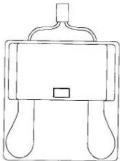
The Soft pedal is located on the left side, and the Damper pedal is on the right side.
Note:
When the Rotary EFX is in use, the Soft pedal changes function to a Fast/Slow Rotor switch.
5. MIDI JACKS
These jacks are used to connect the MP9500 with external MIDI devices such as a MIDI sound module or a MIDI sequencer.
6. POWER SWITCH
Turns the MP9500 ON or OFF.
7. POWER RECEPTACLE
Connect the power cable, which is included in the MP9500 package, to this receptacle.
![graph TD A["PA equipments (Ex. Mixer, Multi-track recorder)"] --> B["FUZO"] B --> C["OUTPUT"] C --> D["1"] D --> E["NORMAL L/MONO"] E --> F["2"] F --> G["3"] G --> H["EXP FOOT CONTROLLER"] G --> I["4"] I --> J["KAWAI Footswitch (optional)"] J --> K["5"] K --> L["6"] L --> M["7"] M --> N["MIDI device…](/content/2026/05/777432/images/6aa7db1e255592b6c3b2a568fdc624e1ad0caeb11c8af08ec33becf3ca5b481d.jpg)
2. SINGLE mode
In this mode, the MP9500 functions as a stand alone digital piano or basic MIDI controller transmitting on one (selectable) MIDI channel.
1) Getting Ready
Turn the MP9500 ON, using the POWER SWITCH on the rear panel. It is recommended to turn the MP9500 on before turning on any amplifiers in order to avoid switching noise.
2) Playing the MP9500 as a stand alone Digital Piano
OPERATION
The MP9500 always starts up in SINGLE mode when the power is turned ON. The SINGLE button will be lit to indicate SINGLE mode is active.
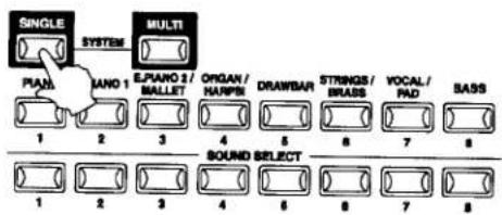
STEP 1
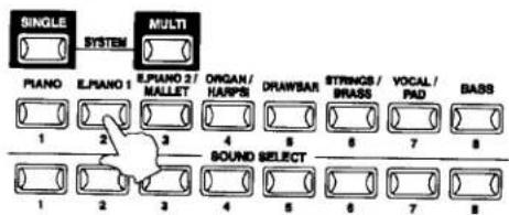
Press any of the PATCH buttons in the upper row to choose a sound category.
STEP 2
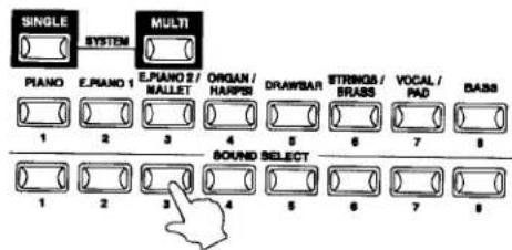
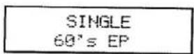
Use any of the PATCH buttons in the lower row to select one of the internal sounds for the category.
Note:
Internal sounds can also be selected using the VALUE buttons.
3) Using the MP9500 as a MIDI controller
The MP9500 transmits MIDI data on one channel when in SINGLE mode.
MIDI Connection
OPERATION
STEP 1
Connect the MIDI OUT on the MP9500 to the MIDI IN on an external MIDI device with a MIDI cable.
Selecting the MIDI Channel
The MIDI Transmit Channel of the MP9500 must be matched with the Receive Channel of any MIDI devices connected to the MP9500.
STEP 2
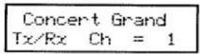
Press the MENU-UP button until "Tx/Rx Ch" (Transmit/Receive Channel) appears on the display.

STEP 3
Use the VALUE buttons to choose a MIDI Transmit/Receive Channel from 1 to 16.
Any notes played on the keyboard or any movements of the Knobs, sliders, etc. will be transmitted to any external MIDI devices connected to the MIDI out of the MP9500 on the selected MIDI channel.
In the MULTI mode, the MP9500 can transmit MIDI data on multiple MIDI channels.
(see p.23 for details)
4) SINGLE Edit
Use the MENU buttons to scroll through the parameters which can be edited in SINGLE mode.
SINGLE Edit Menu list:
Voicing
Tx/Rx Ch
Volume Asgn
FootSW Asgn
ExpPdl Asgn
The Voicing can be set separately for each of the 64 internal sounds. The other parameters in the SINGLE menu are Global.
Caution:
The changes made in the SINGLE Edit Menu will not be stored when the power is turned off. To Save these settings, use the Store SINGLE procedure. (see p.33)
How to change the SINGLE Edit parameters
OPERATION
Make sure that the SINGLE button is lit.
STEP 1
Use the MENU buttons to scroll to the parameter you want to edit.
STEP 2

Use the VALUE buttons to change the value of the parameter. (see p.15 for details)
STEP 3

Save these settings using the STORE button. (see p.33 for details)
Voicing
[Available Voicing types: Normal/Mellow/Dynami/Bright]
Concert Grand Voicing = Normal
Voicing is a technique used by traditional piano technicians to mold the character of an acoustic piano's sound by physically adjusting the action, hammers and strings. The MP9500 voicing parameter simulates this technique electronically.
This function is a very powerful way to enhance and customize each sound in the MP9500.
The effect is most useful on the Piano sounds, but is available for all of the Internal Sounds.
Normal: Produces the normal tone of an acoustic piano throughout the entire dynamic range.
Mellow: Produces a mellower tone throughout the entire dynamic range.
Dynami: This setting is not possible with an acoustic piano. Softly played notes will have the tone of a mellow voicing and notes played harder will have the tone of a bright voicing. This setting produces a dramatic change from mellow to bright throughout the entire dynamic range.
Bright: Produces a brighter tone throughout the entire dynamic range.
Tx/Rx Ch (Transmit/Receive Channel)
[Value Range: 1 - 16]
Concert Grand Tx/Rx Ch = 1
This parameter selects the MIDI channel that will be used for transmitting and receiving MIDI data in SINGLE mode. This MIDI channel must be matched to an external MIDI device. (see p.13)
Volume
[Available types: Int/Ext/Both]
Concert Grand Volume Asgn=Int
This parameter selects the assignment of Fader 1. This fader can be assigned to control the volume (CC#7) of internal sounds only, external MIDI devices only, or both simultaneously.
Int: Assigns Fader 1 to Internal sounds only.
Ext: Assigns Fader 1 to external MIDI devices only.
Both: Assigns Fader 1 to both internal sounds and external MIDI devices.
FootSW (Foot Switch)
[Available types: Int/Ext/Both]
Concert Grand FootSW Asgn=Int
This parameter selects the assignment of the FootSwitch. The FootSwitch can be assigned to control internal sounds only, external MIDI devices only, or both simultaneously.
Int: Assigns the FootSwitch to Internal sounds only.
Ext: Assigns the FootSwitch to External MIDI devices only.
Both: Assigns the FootSwitch to both internal sounds and external MIDI devices.
ExpPdl (Expression Pedal)
[Available types: Int/Ext/Both]
Concert Grand ExpPd1 Asgn=Int
This parameter selects the assignment of the Expression Pedal. The Expression Pedal can be assigned to control internal sounds only, external MIDI devices only, or both simultaneously.
Int: Assigns the Expression Pedal to Internal sounds only.
Ext: Assigns the Expression Pedal to External MIDI devices only.
Both: Assigns the Expression Pedal to both internal sounds and external MIDI devices.
5) TRANSPOSE
When the Transpose function is "ON" the MP9500's key can be raised or lowered in half steps. The available range of transposition is 24 semitones, either up or down.
OPERATION
Method 1
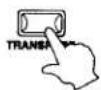
While holding down the TRANSPOSE button, press any key on the MP9500 keyboard to select a new transposed key. Pressing the F key above middle C for example will transpose the MP9500 UP to the key of F (+5 half steps).

Method 2
The transpose amount can also be set using the VALUE buttons. While holding the TRANSPOSE button down, press the VALUE buttons to change the transpose amount.
The display shows the current TRANSPOSE amount when the TRANSPOSE button is held down. A value of "0" indicates no transposition.
Transpose +10
6) EFX/REVERB
The internal sounds of the MP9500 can be enhanced using the built in REVERB and EFX generators.
There are 7 REVERB types and 21 different EFX types to choose from.
EFX
The MP9500 contains 21 high quality EFX types, designed to complement the internal sounds.
EFX ON/OFF
Each internal sound has a preset effect assigned as the default. The EFX button turns the EFX generator ON or OFF for the selected sound.
OPERATION
STEP 1
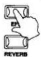
To turn the EFX "ON" for the current sound, press the EFX button and the button will light up. EFX will be added to the current sound.
To turn the EFX "OFF" again, press the EFX button again (The light on the button will be turned OFF).
EFX type
[Available EFXtypes: Chorus 1,2,3/Flangr 1,2/Ensemble/Celeste/Delay 1,2/AutoPan/Tremolo/Phaser 1,2/Rotary 1,2/Autwah/Exciter/Enhancr/Overdrv/Distrtn/SympRes]
OPERATION
STEP 1
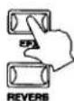
Press and hold the EFX button until the display shows EFX Type.
EFX Type 14:Rotary1
STEP 2
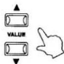
Use the VALUE buttons to change the effect type. Each EFX type has a default value for RATE and DEPTH, so when changing the EFX type, the values are changed automatically.
EFX type list;
Chorus 1/2/3: Chorus is a slight detuning of the sound, which adds depth and richness to the sound.
Flangr 1/2: Flanger introduces a shifting comb-filter, which adds motion and a "hollow" tone to the sound.
Ensemble: Ensemble is a three phase chorus, with each of the three chorus units at a different phase and frequency. This gives a slightly richer sound than the Celeste effect, below.
Celeste: Celeste is a three phase chorus, with each of the three chorus units at different phase.
Delay 1/2: Delay adds echoes to the sound.
AutoPan: AutoPan alternates the sound left and right across the stereo field at a variable rate.
Tremolo: Tremolo changes the volume of the sound, making it louder and softer at a variable rate.
Phaser 1/2: Phaser creates a cyclic phase change, adding motion to the sound.
Rotary 1/2: The Rotary effect simulates the sound of the rotary speaker cabinet commonly used with electronic organs. Rotary 2 adds distortion.
Auto Wah: Auto Wah creates an automatic filter sweep at the attack of each note.
Exciter: Exciter emphasizes certain high frequencies to make a sound more easily discernible.
Enhancer: Enhancer produces a crisper tone, so the sound is more easily discernible.
Overdrv: Overdrive effect adds pre-amp style distortion.
Distirtn: Distortion effect adds a harder, fuzzier distortion than the overdrive.
SympRes: This effect simulates the sympathetic resonance occurring in the undamped strings of an acoustic piano.
REVERB
The MP9500 contains 7 high quality REVERB types, designed to complement the internal sounds.
REVERB ON/OFF
Each internal sound has a preset REVERB type assigned as the default. The REVERB button turns the REVERB generator ON or OFF for the selected sound.
OPERATION
STEP 1

To turn the REVERB "ON" for the current sound, press the REVERB button and the button will light up. REVERB will be added to the current sound.
To turn the REVERB "OFF" again, press the REVERB button again (The light on the button will be turned OFF).
REV type
[Available REVERB types: Hall 1/Hall 2/Stage 1/Stage 2/Room 1/Room 2/Plate]
OPERATION
STEP 1
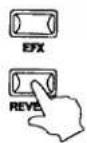
Press and hold the REVERB button until the display shows REVERB Type.
REVERB Type 1:HALL1
STEP 2

Use the VALUE buttons to change the REVERB type. Each REVERB type has a default value for RATE and DEPTH, so when changing the REVERB type, the values are changed automatically.
REVERB type list;
Hall 1 : Simulates the reverb in a standard hall
Hall 2 : Simulates the reverb in a small hall
Stage 1 : Simulates the reverb on a standard stage
Stage 2 : Simulates the reverb on a small stage
Room 1 : Simulates the reverb in a standard room
Room 2 : Simulates the reverb in a small room
Plate : Simulates the reverb of a metallic plate
Adjusting the EFX/REVERB value using the CONTROL KNOBS
OPERATION
STEP 1
Make sure that the EFFECT button in the CONTROL KNOBS section is lit. If the EFFECT button is turned off, press it to turn it ON.

STEP 2
The CONTROL KNOBS are now active and assigned to the EFX/REVERB parameters. Use the CONTROL KNOBS to change the current settings.
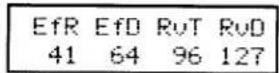
EfR (EFX Rate) adjusts the value of the preset parameter for each EFX. EfD (EFX Depth) adjusts the depth of the EFX added to the sound. RvT (REVERB Time) adjusts the reverb time. RvD (REVERB Depth) adjusts the depth of the reverb added to the sound.
EFX parameter list
| EFX Rate | EFX Depth | |||
| 1. | CHORUS 1 | rate | 0 -12.7Hz | send level |
| 2. | CHORUS 2 | rate | 0 -12.7Hz | send level |
| 3. | CHORUS 3 | rate | 0 -12.7Hz | send level |
| 4. | FLANGER 1 | rate | 0 -12.7Hz | send level |
| 5. | FLANGER 2 | rate | 0 -12.7Hz | send level |
| 6. | ENSEMBLE | rate | 0 -12.7Hz | send level |
| 7. | CELESTE | rate | 0 -12.7Hz | send level |
| 8. | DELAY 1 | delay time | 0 -100 (%) | send level |
| 9. | DELAY 2 | delay time | 0 -100 (%) | send level |
| 10. | AUTO PAN | rate | 0 -12.7Hz | wet balance |
| 11. | TREMOLO | rate | 0-12.7Hz | wet balance |
| 12. | PHASER 1 | rate | 0-12.7Hz | wet balance |
| 13. | PHASER 2 | rate | 0-12.7Hz | wet balance |
| 14. | ROTARY 1 | rate | slow/fast | wet balance |
| 15. | ROTARY 2 | rate | slow/fast | wet balance |
| 16. | AUTO WAH | sense | 0 -100 (%) | wet balance |
| 17. | EXCITER | intensity | 0 -100 (%) | send level |
| 18. | ENHANCER | intensity | 0 -100 (%) | send level |
| 19. | OVERDRIVE | drive | 0 -100 (%) | wet balance |
| 20. | DISTORTION | drive | 0 -100 (%) | wet balance |
| 21. | SYMPRES | early ref level | 0 -100 (%) | send level |
REVERB parameter list
| REVERB Time | REVERB Depth | ||
| 1. REV HALL 1 | rev.time | 0.3 - 5.0S | send level |
| 2. REV HALL 2 | rev.time | 0.3 - 5.0S | send level |
| 3. REV STAGE 1 | rev.time | 0.3 - 5.0S | send level |
| 4. REV STAGE 2 | rev.time | 0.3 - 5.0S | send level |
| 5. REV ROOM 1 | rev.time | 0.3 - 5.0S | send level |
| 6. REV ROOM 2 | rev.time | 0.3 - 5.0S | send level |
| 7. REV PLATE | rev.time | 0.3 - 5.0S | send level |
Note:
When EFX/REVERB depth is set to 0 while the EFX/REVERB button is active, the EFX/REVERB button will blink to indicate that the EFX/ REVERB is turned ON but the depth is set to 0.
7) EQ (EQUALIZER)
The MP9500 contains a four-band graphic equalizer to shape the overall tone of the sound. The EQ is global, and will affect the internal sounds only.
OPERATION
STEP 1
Be sure that the EQ button in the CONTROL KNOBS section is lit. If the EQ button is turned off, press it to turn it ON.

STEP 2
The CONTROL KNOBS are now active and assigned to the EQ parameters. Use the CONTROL KNOBS to change the current settings. Each parameter of the EQ has an adjustable range from -6 to +6. A positive (+) value indicates amplification, or a boost of that frequency range. A negative (-) value indicates attenuation, or a cut of that frequency range.
| Lo | Mlo | Mhi | Hi |
| +3 | -2 | +1 | +2 |
Note:
The EQ function has no effect on the FIXED Outputs of the MP9500.
8) TONE MODIFY
The MP9500 allows certain characteristics of the internal sounds to be custom tailored to suit a particular musical or playing style, or to create many variations and different types of sounds.
The following parameters are provided:
CUTOFF, ATTACK, DECAY and RELEASE.
OPERATION
STEP 1
Make sure that the TONE MODIFY button in the CONTROL KNOBS section is lit.
If the TONE MODIFY button is turned off, press it to turn it ON.

STEP 2
The CONTROL KNOBS are now active and assigned to the Tone Modify parameters for the current sound.
Use the CONTROL KNOBS to change the current settings.
Each parameter of the TONE MODIFY function has an adjustable range from -50 to +50.
CUT amp; ATK amp; DCY amp; RLS + 5 0 amp; - 2 0 amp; + 4 0 amp; + 1 0
TONE MODIFY parameter list
CUTOFF: Raising the CUTOFF level makes the sound brighter, lowering the level makes the sound duller.
ATTACK: As the value increases, the attack time becomes longer, which means a slower attack is produced.
DECAY: This parameter controls the amount of time from the peak level to the sustain level of the sound.
RELEASE: This parameter controls the amount of time needed for the sound to fade out after the key is released.

9) Transmitting MIDI Control Changes using the CONTROL KNOBS
The MP9500 can send any MIDI Continuous Controller information to any MIDI Instrument or Device.
This powerful feature allows for editing the sounds of an external sound module in Real Time during performance, or for recording Real Time performance edits to a MIDI sequencer. Obviously, the MIDI Control Change function is available for the external MIDI devices only.
OPERATION
STEP 1
Make sure that the MIDI CC# button in the CONTROL KNOBS section is lit. If the MIDI CC# button is turned off, press it to turn it ON.

STEP 2
The CONTROL KNOBS are now active and assigned to the MIDI CC parameters. Use the CONTROL KNOBS to send the MIDI continuous controller information assigned to each knob as described below. Each parameter of the Control Change has an adjustable range from 0 to 127.
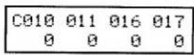
Control Change parameter list;
A: #10 PAN
B: #11 EXPRESSION
C: #16 GENERAL PURPOSE#1
D: #17 GENERAL PURPOSE#2
Note:
Control Change Numbers are fixed in the SINGLE mode.
In the MULTI mode, different Control Numbers can be assigned to each knob individually for each zone. (see p.30)
3. MULTI mode
This mode allows access to all of the available parameters in the MP9500. This collection of settings is called a MULTI. The MP9500 provides 64 MULTIs, and all are user programmable.
The following groups of parameters are stored in a MULTI.
TRANSPOSE (see p.16)
CONTROL KNOBS (see p.19)
EFX/REVERB (see p.16)
EDIT Int/Ext (see p.25)
1) MULTI Recall
Each MULTI is designated by both a name and by a two-digit number, for quick access.
OPERATION
STEP 1
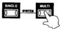
To enter the MULTI mode, press the MULTI button and the MULTI button will light up.
When entering the MULTI mode, the MP9500 returns to the most recently used MULTI.
MULTI PNO+STR
STEP 2
Choose a MULTI using the PATCH buttons. First press any PATCH button in the upper row to select a MULTI bank, then press any PATCH button in the lower row to select a MULTI patch from that bank. For example, to recall 6-4 MULTI, press the PATCH buttons "6" in the top row, and "4" in the bottom row.

The display will confirm the current MULTI.
MULTI MULTI6-4
2) MULTI Edit
A MULTI consists of four zones. Each zone can be set as Internal, External or Both individually. Inside each of the four zones, a multitude of features and effects can be programmed and combined together into one exciting MULTI.
A total of 64 MULTIs may be programmed in this way.
The menu consists of two categories: Internal Edit and External Edit. If a zone is set as Both, both the Internal Edit menu and External Edit menu are available for the zone.
Use the MENU buttons to scroll through all the different parameters.
Internal Edit
| Sound | Pan | Prg#, Bank | Bender |
| K. Range Lo/Hi | Fine Tune | Tx Channel | Pan |
| Vel SW | Voicing | K. Range Lo/Hi | Fine Tune |
| Vel sens | Vel SW | Knob A/B/C/D | |
| Transpose | Vel sens | Tx Cutoff | |
| Volume | Transpose | Tx Attack | |
| Damper | Volume | Tx Decay | |
| Foot sw | Damper | Tx Release | |
| Exp Pedal | Foot sw | Solo | |
| Modulation | Exp Pedal | Solo Mode | |
| Bender | Modulation |
External Edit
Caution:
The settings in the MULTI Menu will not be stored when the power is turned off, unless they are saved. To save these settings, use the Store MULTI procedure. (see p.34)
How to change the MULTI Edit parameters
OPERATION
Make sure that the MULTI button is lit.
STEP 1
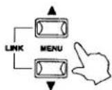
First, press the ZONE SELECT button for the zone to be edited.
Next, press the MENU buttons until the parameter you want to edit appears in the DISPLAY. When a zone is set as Both, pressing the ZONE SELECT button again will switch the menu list from Internal to External or vice versa.
STEP 2

Set the value of the parameter using the VALUE buttons.
Since each parameter has a different value range, consult the following pages for the details. Repeat this procedure for any other parameters in any of the zones that need to be modified.
STEP 3

Save these settings using the STORE button.
(see p.34 for detail)
Edit Common
Each zone can be set as Int, Ext or Both. This is called Zone mode. The first page of MULTI Edit menu shows the Zone mode status for all zones.
Zone Mode
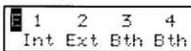
This page shows the Zone Mode for all four zones. The reversed letter in the left upper corner shows the status of the selected zone mode. To change the Zone mode, go to the next page.
Zone Mode (Edit)
[Value Range: Int/Ext/Bth]
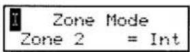
This parameter sets the Zone mode. The example shows that the Zone 2 is set to Internal.
Edit Zone
Zone No. Zone Mode
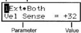
There are two parameter groups. Internal parameter group and External parameter group. If a zone is set to Int, only Internal parameters are available for editing. If a zone is set to Ext, only External parameters are available for editing. If a zone is set to Bth, both Internal and External parameters are available for editing.
Sound
[Value Range: 64 internal sounds]

This parameter determines which internal sound is assigned for the selected zone.
TX Prg #
[Value Range: On/Off]

This parameter determines if a Program Change Number will be transmitted (On) or not (Off) when a MULTI is recalled.
Prg #
[Value Range: 1 \~ 128]
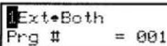
This parameter determines which Program Change Number will be transmitted when a MULTI is recalled. When the TX Prg # is set to Off, this page won't be displayed.
TX Bank
[Value Range: On/Off]

This parameter determines if Program Bank Numbers (MSB, LSB) will be transmitted (On) or not (Off) when a MULTI is recalled.
Bank MSB/LSB
[Value Range: 0 \~ 127]

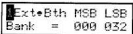
This parameter determines which MSB and LSB Number will be transmitted when this MULTI is recalled. When the TX Bank is set to Off, this page won't be displayed.
In the MIDI standard, there are 128 storage spaces. The number of storage spaces can be expanded using an MSB and an LSB.
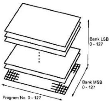
This is a 3D image of the expanded program change system with the MSB and LSB. To use these efficiently and correctly, refer to the operation manual of any external MIDI sound modules that are connected to the MP9500.
TX Ch
[Value Range: 1 \~ 16]
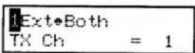
This parameter sets the MIDI transmit channel for the selected zone. All MIDI data for the selected zone will be transmitted on this channel. Make sure that the receiving channel for any external MIDI devices to be controlled from this zone are set to the same channel as the zone.
K.Range Hi/Lo
[Value Range: C-2 \~ G8]

These two parameters define the playable key range on the keyboard for the selected zone. First, while K.Range Hi appears in the display, press the key on the keyboard that will be the highest note that the selected zone can play. Next, while K.Range Lo appears in the display, press the key on the keyboard that will be the lowest note that the selected zone can play.
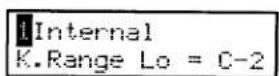


Note:
For convenience, the keyboard is used to set the values for K.Range Hi and K.Range Lo. Be careful not to leave the K.Range Hi or K.Range Lo parameters active in the display after these values have been set!
Note:
The K.Range Hi and K.Range Lo can be also set using the VALUE buttons.
TIPS
An effective use of the K.Range Hi and Lo
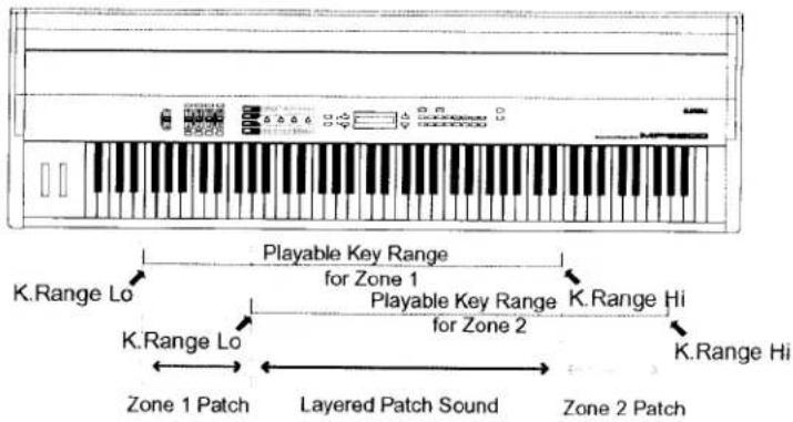
(1) Assign a patch to the Zone 1 and a different patch to the Zone 2 using the regular method.
(2) For the Zone 1, set K.Range Lo to "F0" and K.Range Hi to "E5".
(3) For the Zone 2, set K.Range Lo to "A1" and K.Range Hi to "G6".
F0 - G1 : These keys will play the Zone 1 only.
A1 - E5 : These keys will play the Zone 1 and 2 as a layer.
F5 - G6 : These keys will play the Zone 2 only.
Vel SW (Velocity Switch)
[Value Range: Off/Loud/Soft]
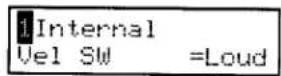
Velocity switching is an extremely useful and creative tool for customizing a performance. Using Velocity Switching, it is possible to have either one sound switch to another sound at a set velocity, or even for a second sound to be added in once a certain velocity has been reached, or to have a sound drop out above or below a set velocity level.
This parameter sets the velocity switch type.
Off : No effect. The PATCH plays normally.
Loud : The selected sound plays only when the key is struck harder than the Vel SW Val. (See next parameter)
Soft : The selected sound plays only when the key is struck softer than the Vel SW Val. (See next parameter)
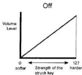
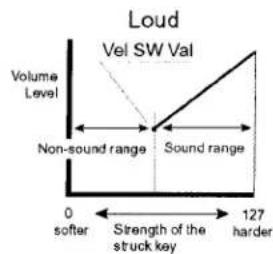
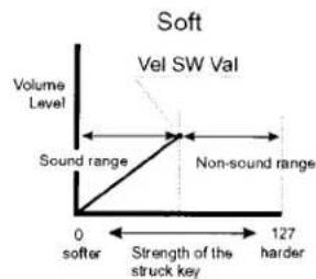
Vel SW Val (Velocity Switch Value)
[Value Range: 0 \~ 127]
Internal Vel SW Val = 80
This parameter determines switching level of the key velocity.
For the Loud Vel SW : determines the lowest key velocity to sound.
For the Soft Vel SW : determines the highest key velocity to sound.
Note:
Each zone can have a separate Velocity Switch Value. By setting the Soft Zone Velocity Switch Value higher than that of the Loud Zone, a dynamic area where both sounds play can be created. It is also possible to switch Internal Zones with External Zones for even more possibilities.
Vel Sense (Velocity Sense)
[Value Range: -64 \~ 0 \~ +63]
Internal Vel Sense = +32
This parameter adjusts the keyboard response.
If a positive value is set, the velocity level increases when keys are struck harder.
On the contrary, if a negative value is set, the velocity level decreases when keys are struck harder.

Vertical Line: Volume level
Horizontal Axis: Strength of the struck key
Transpose
[Value Range: -36 \~ 0 \~ +36]
- Internal Transpose = 0
This parameter sets the amount of transposition. The available range is three octaves above or below middle C (C3).
This parameter can be set for each zone separately in the MULTI Edit menu.
(To set the master transpose, press the TRANSPOSE button and set the value.)
TX Volume (Transmitting Volume)
[Value range: On/Off]

This parameter determines if an initial MIDI Volume message will be transmitted (On) or not (Off) when a MULTI is recalled.
Note:
In a zone set to External or Both moving the faders will still transmit volume messages even if TX Volume is set to Off.
Volume
[Value range: 0 \~ 127]
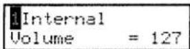
This parameter sets the volume level for the selected zone. The value can be changed by using the FADER or VALUE buttons.
For External zones, when the TX Volume is "Off", this page won't be displayed.
Damper
[Value Range: On/Off]
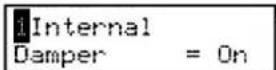
This parameter determines if the damper pedal is active (On) or not (Off) for the selected zone.
FootSW
[Value Range: On/Off]

This parameter determines if a Foot Switch connected to the FSW jack is active (On) or not (Off) for the selected zone.
ExpPedal
[Value Range: On/Off]
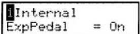
This parameter determines if an Expression Pedal connected to the EXP jack is active (On) or not (Off) for the selected zone.
Modulation
[Value Range: On/Off]

This parameter determines if the Modulation Wheel is active (On) or not (Off) for the selected zone.
Bender
[Value Range: On/Off]

This parameter determines if the Bender Wheel is active (On) or not (Off) for the selected zone.
TxBnderRng (Transmitting Bender Range)
[Value Range: On/Off]

This parameter decides if a Bender Range should be transmitted (On) or not (Off) when a MULTI is recalled.
Bender Range
[Value Range: (Int) 0 \~ 7 / (Ext) 0 \~ 12]
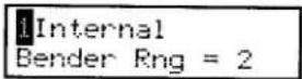
Int: This sets the Bender Range in semitone steps.
Ext: This is used to transmit Bender Range information to external sound modules. If the TX Bender Range is "On", the value is transmitted when a MULTI is recalled. When the TXBendrRng is "Off", this page won't be displayed.
TX Pan (Transmitting Pan)
[Value Range: On/Off]
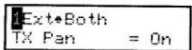
This parameter determines if a Pan setting will be transmitted (On) or not (Off) when a MULTI is recalled.
Pan
[Value Range: L63 \~ 0 \~ R63]

Int: This sets the pan-pot: (the L. R. balance)
Ext: This sets the pan-pot value that will be transmitted to external sound modules. If the TX Pan is "On", the value is transmitted when a MULTI is recalled. When the TX Pan is "Off", this page won't be displayed.
TxFineTune (Transmitting Fine Tune)
[Value Range: On/Off]
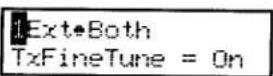
This parameter determines if Fine Tuning settings will be transmitted (On) or not (Off) when a MULTI is recalled.
Fine Tune
[Value Range: -63 \~ 0 \~ +63]

Int: This is a fine tuning function for values smaller than a semi-tone.
Ext: This is used to transmit fine tuning settings to external sound modules. If the TxFineTune is "On", the value is transmitted when a MULTI is recalled. When the TxFineTune is "Off", this page won't be displayed.
Knob [A-D] CC# (Knob A-D/Control Change No.)
[Value Range: 0-114]
![KAWAI MP9500 - Knob [A-D] CC# (Knob A-D/Control Change No.) - 1](/content/2026/05/777432/images/30a09282e5946614e1ae37f7184ea298b81635bb941616bee276ce18c08d02fc.jpg)
This parameter specifies the Control Change Number for the four Control Knobs.
See p.61 for the available Control Change Numbers.
Note:
The assigned Control Changes are transmitted whenever the Control Knobs are moved, even when the "TX Knob [A-D]" are "Off".
TX Knob [A-D]
[Value Range: On/Off]
![KAWAI MP9500 - TX Knob [A-D] - 1](/content/2026/05/777432/images/307e17d16078e60606b54ac8154e50bc0f5ca690ed853d82990701b103c23720.jpg)
This parameter determines if an initial Control Change message for each of the four Control Knobs will be transmitted (On) or not (Off) when a MULTI is recalled.
TX Cutoff (Transmitting Cutoff)
[Value Range: On/Off]

This parameter determines if a Cutoff setting will be transmitted (On) or not (Off) when a MULTI is recalled.
Note:
Cutoff setting is transmitted whenever the Control Knob is moved, even when the "TX Cutoff" is "Off".
TX Attack (Transmitting Attack)
[Value Range: On/Off]
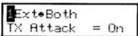
This parameter determines if an Attack setting will be transmitted (On) or not (Off) when a MULTI is recalled.
Note:
Attack setting is transmitted whenever the Control Knob is moved, even when the "TX Attack" is "Off".
TX Decay (Transmitting Decay)
[Value Range: On/Off]
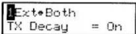
This parameter determines if a Decay setting will be transmitted (On) or not (Off) when a MULTI is recalled.
Note:
Decay setting is transmitted whenever the Control Knob is moved, even when the "TX Decay" is "Off".
TX Release (Transmitting Release)
[Value Range: On/Off]

This parameter determines if a Release setting will be transmitted (On) or not (Off) when a MULTI is recalled.
Note:
Release setting is transmitted whenever the Control Knob is moved, even when the "TX Release" is "Off".
Voicing
[Available types: Normal/Mellow/Dynami/Bright]

This parameter re-creates electronically the voicing technique of adjusting the action, hammers and strings on an acoustic piano to change the tone character. This function is a very powerful way to enhance and customize the piano response for each player and each sound.
The effect is most useful on the Piano sounds, but is available for all of the internal sounds.
Voicing type list;
Normal: Produces the normal tone of an acoustic piano throughout the entire dynamic range.
Mellow: Reproduces the effect of a softer hammer surface. Produces a mellower tone throughout the entire dynamic range.
Dynami: This setting is not possible with an acoustic piano. Softly played notes will have the tone of a mellow voicing and notes played harder will have the tone of a bright voicing. This setting produces a dramatic change from mellow to bright throughout the entire dynamic range.
Bright: Produces a brighter tone throughout the entire dynamic range.
Solo
[Value Range : On/Off]
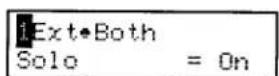
This parameter turns the Solo Mode On/Off.
When Solo is turned "On" only one note will be transmitted via MIDI for the selected zone even if more than one note is being played simultaneously. This can be used to effectively simulate the performance characteristics of a monophonic synthesizer or as a special performance tool for playing solo parts. Solo mode can also be used while playing a polyphonic part from another zone.
Solo Mode
[Available types: Last/Hi/Low]
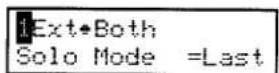
This parameter determines which note will be played when Solo is ON and more than one note is being played simultaneously. There are three choices for Solo note priority.
Last: The most recently played note within a group of notes will be transmitted when Solo is ON
Hi: The highest note played within a group of notes will be transmitted when Solo is ON.
Low: The lowest note played within a group of notes will be transmitted when Solo is ON.
4. STORE
1) Store SINGLE
The Store SINGLE procedure is executed in the SINGLE mode. The Control Knob values and the SINGLE Menu settings are stored. The settings in the SINGLE mode won't be stored after the power is turned off, unless they are saved.
OPERATION
STEP 1

To begin, press the STORE button.
Store SINGLE Press VALUE UP
STEP 2

Press the VALUE-UP button. The display will change.
Store SINGLE sure?
The display will ask for confirmation. To cancel Store SINGLE at this point, press the VALUE-DOWN button. Otherwise, go on to the STEP 3.
STEP 3
To execute Store SINGLE, press the VALUE-UP button again. The SINGLE mode settings are now stored. The display will change.
Store SINGLE Completed!
By using the Store SINGLE function, the settings are saved even when the power is turned off. To reset the patch settings to the factory preset, see p.38-39 "Reset Current" or "Reset All" for detail.
Note: In the Store SINGLE, the VALUE-UP button represents "YES", the VALUE-DOWN button represents "NO".
2) Store MULTI
The MP9500 is capable of storing 64 MULTIs. In the Store MULTI procedure, the Control Knob values, TRANSPOSE and all of the MULTI Menu parameters for each zone are stored.
The settings in the MULTI mode will not be stored if another MULTI is recalled, or if the power is turned off unless they are saved.
OPERATION
STEP 1
Press the STORE button.

Store MULTI Rename?
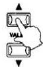
MULTIs can be named with a maximum of 8 letters.
Press the MENU-UP button in order to go ahead without renaming the MULTI.
To rename the MULTI, press the VALUE-UP button.
Rename MULTI Name = MULTI6-4
![graph LR A["LINK"] --> B["MENU"] B --> C["VALUE"] C --> D["Hand gestures"]](/content/2026/05/777432/images/9a2268839c7f387a55e33e7242008682c819b8b81c604292e8f79e42aa60ccda.jpg)
Use the MENU-UP/DOWN buttons to move the cursor, use the VALUE UP/DOWN buttons to select the character.
Available characters:
(SPACE)!" # % \ amp;^ () * +, -. / 0 - 9:; lt; = gt;? @ A - Z [] _ - a - z | | →
STEP 2
Select a MULTI location to save to, using a two-digit MULTI number. Select the first digit from the top row of patch buttons. Select the second digit from the bottom row of patch buttons.
For example, in order to store the MULTI setting to 6-4 MULTI, press the PATCH buttons "6" from the top row of patch buttons and "4" from the bottom row of patch buttons.

Store MULTI to 6-4 MULTI6-4
STEP 3
Press the VALUE-UP button.
The display will change.

Store MLTI Sure? to 6-4 MULTI6-4
The display will ask confirmation.
To cancel Store MULTI at this point, press the VALUE-DOWN button.
Otherwise, go on to the STEP 4.
STEP 4
Press the VALUE-UP button again.
The MULTI has been stored to the designated MULTI location.
Store MULTI Completed!
Note:
In the Store MULTI, the VALUE-UP button represents "YES", the VALUE-DOWN button represents "NO".
3) Block Dump
This function transmits the MULTI settings of the MP9500 as System Exclusive Messages via the MIDI OUT in two bulk messages. The Block Damp 1 transmits the first 32 MULTI settings (1-1 - 4-8) and the Block Damp 2 transmits the last 32 MULTI settings (5-1 - 8-8).
OPERATION
STEP 1

Press the STORE button.

And then press the MENU-UP button until "Block Dump" appears on the display.
Block Dump 1 Press VALUE UP
STEP 2
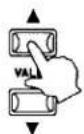
Press the VALUE-UP button.
Block Dump 1 Sure?
The display will ask for confirmation.
To cancel Dump All at this point, press the VALUE-DOWN button. Otherwise, go on to the STEP 3.
STEP 3

Press the VALUE-UP button again. When the data is done transmitting, the display will change to read "Completed!!" Dump All is complete.
Block Dump 1 Completed!!
Note: In the Block Dump, the VALUE-UP button represents "YES", the VALUE-DOWN button represents "NO".
4) Dump Current
This function transmits the current and active settings of the MP9500 as a System Exclusive Message via the MIDI OUT.
(In the SINGLE mode, only SINGLE mode data is sent. In the MULTI mode, the current values for all MULTI parameters are transmitted.)
OPERATION
STEP 1
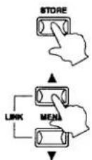
Press the STORE button.
And then press the MENU-UP button until "Dump Current" appears on the display.
Dump Current Press VALUE UP
STEP 2
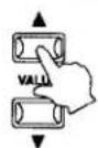
Press the VALUE-UP button.
Dump Current Sure?
The display will ask for confirmation.
To cancel Dump Current at this point, press the VALUE:DOWN button. Otherwise, go on to the STEP 3.
STEP 3
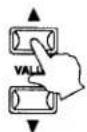
Press the VALUE-UP button again.
The display will change to read "Completed!!" Dump Current is complete.
Dump Current Completed!!
Note: In the Dump Current, the VALUE-UP button represents "YES", the VALUE-DOWN button represents "NO".
5) Reset Current
This function resets the current SINGLE or MULTI back to the original factory default settings.
OPERATION
STEP 1

Press the STORE button.
And then press the MENU-UP button until "Reset Current" appears on the display.
Reset Current Press VALUE UP
STEP 2

Press the VALUE-UP button.
Reset Current Sure?
The display will ask for confirmation.
To cancel Reset Current at this point, press the VALUE-DOWN button. Otherwise, go on to the STEP 3.
STEP 3

Press the VALUE-UP button again.
The display will change to read "Completed!!" Reset Current is complete.
Reset Current Completed!!
Note:
In the Reset Current, the VALUE-UP button represents "YES", the VALUE-DOWN button represents "NO".
6) Reset All
This function performs a global reset of all 64 SINGLEs, all 64 MULTIs and SYSTEM settings back to the original factory default settings.
OPERATION
STEP 1

Press the STORE button.
And then press the MENU-UP button until "Reset All" appears on the display.

Reset A11 Press VALUE UP
STEP 2
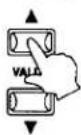
Press the VALUE-UP button.
Reset All Sure?
The display will ask for confirmation.
To cancel Reset All at this point, press the VALUE-DOWN button. Otherwise, go on to the STEP 3.
STEP 3
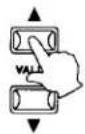
Press the VALUE-UP button again. The display will change to read "Completed!" Reset All is complete.
Reset All Completed!!
Note: In the Reset All, the VALUE-UP button represents "YES", the VALUE-DOWN button represents "NO".
5. LINK
1) LINK setting
Using the LINK function, up to 32 performance settings, either any of the 64 MULTIs, or any of the 64 SINGLEs, can be chained together in any order. In performance, simply pressing one button or tapping a pedal will instantly recall the next step in the LINK. The LINK function is convenient when moving quickly from one performance setting to another. This is extremely useful; especially for live performances.
Caution:
The settings in the LINK will not be retained when the power is turned off unless they are saved. To save these settings, use the Store LINK procedure.
How to program a LINK
OPERATION
STEP 1
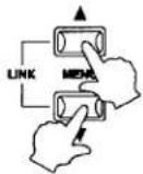
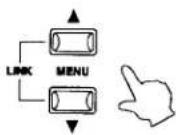
To enter the LINK function, press the MENU-UP and MENU-DOWN buttons simultaneously.
• for MULTI
• for SINGLE
LINK No. 1 2-3 MULTI2-3
LINK No.16 Concert Grand
Note:
To cancel the LINK function, press the MENU-UP and MENU-DOWN buttons simultaneously again.
STEP 2

The LINK function has 32 locations, or STEPS. Use the MENU-UP and MENU-DOWN buttons to move through the different STEPS.
STEP 3
Using the SINGLE, MULTI and PATCH buttons, select a performance setting for the current STEP of the LINK.
Repeat Steps 2 & 3 for each of the STEPS in the LINK.

Note:
The MULTIs and SINGLEs can be also be set using the VALUE-UP and VALUE-DOWN buttons.
2) Store Link
The settings in the LINK function won't be stored after the power is turned off, so to save the current settings, they must be stored using the Store LINK function.
OPERATION
Make sure that the LINK function is on.
STEP 1

Press the STORE button.
Store Link Press VALUE UP
STEP 2

Press the VALUE-UP button.
Store Link Sure?
The display will ask for confirmation. To cancel Store Link at this point, press the VALUE-DOWN button. Otherwise, go on to the STEP 3.
STEP 3

To execute Store Link, press the VALUE-UP button again. The current LINK settings are now stored. The display will change to read "Completed!!".
Store Link Completed!!
Note: In the Store LINK, the VALUE-UP button represents "YES", the VALUE-DOWN button represents "NO".
6. SYSTEM mode

Use this mode to set the global System parameters of MP9500. To enter the SYSTEM mode, press the SINGLE button and the MULTI button simultaneously.
1) System Menu
Use the MENU buttons to scroll through the System parameters.
System Ch
Touch
Temperament
Key of Temperament
System Tuning
Foot Switch CC#
Expression Pedal CC#
Local On/Off
Receive Channel Mute
LCD Contrast
The System Menu parameters are always stored when leaving the SYSTEM mode, so there is no need to store them.
How to change the SYSTEM Edit parameters
OPERATION
Make sure that both the SINGLE and MULTI buttons are lit.
STEP 1

Press the MENU buttons until the parameter you want to edit appears in the DISPLAY.
STEP 2
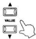
Set the value of the parameter by using the VALUE buttons. The value range differs depending on the parameter.
System Ch (System Channel)
[Value Range: 1 - 16 (Ch)]
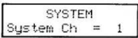
This parameter sets the System MIDI channel on which System Exclusive messages are transmitted/received.
Touch
[Available touch response curves: [Off/Heavy+/Heavy/Normal/Light/Light+/User1,2]
This parameter adjusts the touch response curve of the keyboard.
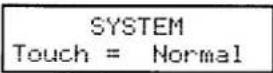

Off: This curve gives a constant velocity level no matter how hard the keyboard is struck. (see 6) This curve is suitable for sounds that have a fixed dynamic range such as Organ, Harpsichord and certain synthesizer sounds.
Heavy+: This Curve has a steep rise as velocity increases, and a shallower curve at low velocities. (see 1) This curve requires the most striking force to produce a loud volume.
Heavy: This curve requires a stronger striking force to produce a loud volume. (see 2) This curve is perfect for those with strong fingers.
Light: This curve requires less striking force to produce a loud volume. (see 4) This curve is good for those still developing finger strength.
Light+: This curve requires the least amount of striking force to produce a loud volume. (see 5) This curve is good for those with a very delicate touch.
Normal: This curve recreates the touch response of an average acoustic piano.
User1,2: You can create your own custom touch curve to fit your playing style. Two user touch curves can be saved.
User Touch
After selecting the "Touch" function by pressing the MENU buttons, use the VALUE buttons to select User 1 or User 2.
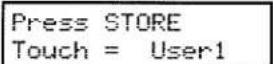
Press the STORE button.

Now start playing the piano dynamically from soft to loud in order to let the piano analyze your playing style.

Press the STORE button again when you finish playing.
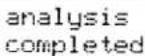
The piano will analyze your playing and create a custom touch curve for you based upon your playing style.
Temperament
[Value Range: Equal/Stretch/Pure M/Pure m/Pytha/Mean/Werk/Kirn/User]
| SYSTEM |
| Tempr = Stretch |
This parameter sets the temperament of the MP9500.
| Equal: | This is "unstretched" equal temperament that divides the scale into twelve equal semitones. |
| Stretch: | The temperament is "stretched" for the piano sounds whenever they are selected. All other sounds will retain the Equal temperament EXCEPT when they are layered with a Piano sound. In this situation both sounds in the layer will be set to Stretched so they will be in tune with each other. If two non piano sounds are layered their tuning will be Equal. |
| Pure Maj:(Min): | This temperament, which eliminates dissonance's for thirds and fifths is still popular for choral music because of its perfect harmony. When playing in a major key select "Pure Maj" and when playing in a minor key select "Pure Min". |
| Pythagor: | This temperament, which uses mathematical ratios to eliminate dissonance for fifths, is very limited for use with chords, but it produces very characteristic melodic lines. |
| Meantone: | This temperament, which uses a mean between a major and minor whole tone to eliminate dissonance for thirds, was devised to eliminate the lack of consonance's experienced with certain fifths for the Mersenne pure temperament. It produces chords that are more beautiful than those with the equal temperament. |
| Werkmeis:Kirnberg: | These two temperaments are placed in between Meantone and Pythagorean. For music with few accidentals, this temperament produces the beautiful chords of the mean tone, but as accidentals increase, the temperament produces the characteristic melodies of the Pythagorean temperament. It is used primarily for classical music written in the Baroque era to revive the original characteristics. |
| User: | You can make your own temperament by raising or lowering the pitch for each half tone. |
Note:
Stretched tuning is a temperament that stretches the tuning of the upper and lower octaves. The lower octaves are tuned flatter and the upper octaves are tuned sharper.
Key of Temperament
[Value Range: C \~ B]
| SYSTEM |
| Tempr Key = C |
Limitless modulation of the key became available only after the invention of Equal temperament. When we use a temperament other than Equal temperament, we must carefully choose the key signature to play in. For example, if the song you are going to play is written in D major, choose "D" as the temperament key.
When Temperament is set to Equal or Stretch, this page won't be displayed.
Tuning C \~ B
[Value Range: -50 \~ +50]
| SYSTEM | |
| C | = +50 |
When the temperament is set to "User", adjust the pitch for each key and create your own temperament.
When the temperament is set to other than User, these pages won't be displayed.
SysTune (System Tuning)
[Value Range: 427.0 \~ 453.0 (Hz)]
| SYSTEM SysTune = 440.0 |
This parameter sets the global master tuning of the MP9500.
FootSW CC# (Footswitch Control Change)
[Value Range: 0 \~ 114, LNK]
| SYSTEMFootSW CC# = 66 |
This parameter assigns a Control Change Number to the Footswitch connected to the FSW jack on the rear panel.
If the LNK is selected, the Footswitch is used to select the next step in the LINK. (LINK Mode must be on) See page 61 for the list of Control Change numbers.
ExpPdl CC# (Expression Pedal Control Change)
[Value Range: 0 \~ 114, AFT]
| SYSTEMExpPd1 CC# = 11 |
This parameter assigns a Control Change Number to the Expression Pedal connected to the EXP jack on the rear panel.
If the AFT is selected, the expression pedal is used to send After Touch information. See page 61 for the list of Control Change numbers.
Note:
When the following Numbers are selected for the FootSW CC# or the ExpPdl CC#, the functions affect the internal sounds, too.
- Modulation Wheel
- Volume
- Pan
- Expression Controller
- Damper Pedal
- Sostenuto
- Soft Pedal
Local Control
[Value Range: On/Off]
| SYSTEM | |
| Local | = 0n |
On: The keyboard of the MP9500 and the internal tone generators are connected. Set this parameter to "On" for normal use.
Off: The internal connection between the keyboard and the tone generators is switched off. This feature will avoid the "Doubled Sound" that results from use with an external sequencer equipped with Soft Thru or Echo Thru.
RX Ch [1-16] (Receive Channel)
[Value Range: Play/Mute]
SYSTEM RX Ch 1 = Play
This parameter determines whether or not a particular MIDI channel will receive incoming MIDI data from an external source. This parameter can be used to filter out data on specific MIDI channels that are not intended for the MP9500.
Play: The MP9500 responds to MIDI data received on this channel. Mute: The MP9500 ignores MIDI data received on this channel.
LCD Contrast
[Value Range: 1 \~ 10]
SYSTEM Contrast = 1 0
This parameter adjusts the contrast of the LCD display. As the value changes higher, the contrast gets sharper.
7. OTHER
MIDI IN
SINGLE mode
When in SINGLE mode, the MP9500 receives the MIDI information coming in the Tx/Rx Channel only. (See p.15.)
For changing the internal sounds via MIDI, refer to the SINGLE Program Number List on the next page.
Note:
When the MP9500 receives the Program Number from 65 to 128 in System Channel (See p.43.), the MP9500 will switch to MULTI mode and the corresponding MULTI patch is recalled. (See the MULTI Program Numbr Table below.) The recalled MULTI patch can be played only from the keyboard of the MP9500.
MULTI mode
When in MULTI mode, the MP9500 can be used as a multi-timbral sound module. playing up to 16 different sounds on 16 MIDI channels.
Note:
When the MP9500 receives the Program Number from 65 to 128 in System Channel (See p.43.), the corresponding MULTI patch is recalled. (See the MULTI Program Numbr Table below.) The recalled MULTI patch can be played only from the keyboard of the MP9500.
When the MP9500 receives the Program Number from 1 to 64 in System Channel (See p.43.), the MP9500 will switch to SINGLE mode and the corresponding SINGLE patch is recalled.
MULTI Program Number Table
| MULTI No. | Prg# | MULTI No. | Prg# | MULTI No. | Prg# | MULTI No. | Prg# |
| 1-1 | 65 | 2-1 | 73 | 3-1 | 81 | 4-1 | 89 |
| 1-2 | 66 | 2-2 | 74 | 3-2 | 82 | 4-2 | 90 |
| 1-3 | 67 | 2-3 | 75 | 3-3 | 83 | 4-3 | 91 |
| 1-4 | 68 | 2-4 | 76 | 3-4 | 84 | 4-4 | 92 |
| 1-5 | 69 | 2-5 | 77 | 3-5 | 85 | 4-5 | 93 |
| 1-6 | 70 | 2-6 | 78 | 3-6 | 86 | 4-6 | 94 |
| 1-7 | 71 | 2-7 | 79 | 3-7 | 87 | 4-7 | 95 |
| 1-8 | 72 | 2-8 | 80 | 3-8 | 88 | 4-8 | 96 |
| 5-1 | 97 | 6-1 | 105 | 7-1 | 113 | 8-1 | 121 |
| 5-2 | 98 | 6-2 | 106 | 7-2 | 114 | 8-2 | 122 |
| 5-3 | 99 | 6-3 | 107 | 7-3 | 115 | 8-3 | 123 |
| 5-4 | 100 | 6-4 | 108 | 7-4 | 116 | 8-4 | 124 |
| 5-5 | 101 | 6-5 | 109 | 7-5 | 117 | 8-5 | 125 |
| 5-6 | 102 | 6-6 | 110 | 7-6 | 118 | 8-6 | 126 |
| 5-7 | 103 | 6-7 | 111 | 7-7 | 119 | 8-7 | 127 |
| 5-8 | 104 | 6-8 | 112 | 7-8 | 120 | 8-8 | 128 |
SINGLE Program Number List
| Sound Name | Prg# | Sound Name | Prg# |
| 1. PIANO | 5. DRAWBAR | ||
| 1 Concert Grand | 1 | 1 Rock Organ | 33 |
| 2 Studio Grand | 2 | 2 Be 3 | 34 |
| 3 Mellow Grand | 3 | 3 Drawbar | 35 |
| 4 Modern Piano | 4 | 4 Drawbar 2 | 36 |
| 5 Rock Piano | 5 | 5 Hi/Lo | 37 |
| 6 Jazz Grand | 6 | 6 2 2/3' Perc | 38 |
| 7 New Age Piano | 7 | 7 4' Perc | 39 |
| 8 Honky Tonk | 8 | 8 Key Click | 40 |
| 2. E.PIANO 1 | 6. STRINGS/BRASS | ||
| 1 Classic EP | 9 | 1 String Pad | 41 |
| 2 Modern EP | 10 | 2 Slow Strings | 42 |
| 3 60's EP | 11 | 3 String Ens | 43 |
| 4 Modern EP 2 | 12 | 4 Synth String | 44 |
| 5 Modern EP 3 | 13 | 5 Brass Section | 45 |
| 6 60's EP 2 | 14 | 6 Synth Brass | 46 |
| 7 Legend EP | 15 | 7 Synth Brass 2 | 47 |
| 8 Electric Grand | 16 | 8 Jump Brass | 48 |
| 3. E.PIANO 2/MALLET | 7. VOCAL/PAD | ||
| 1 Classic EP 2 | 17 | 1 Choir Aahs | 49 |
| 2 Classic EP 3 | 18 | 2 Itopia | 50 |
| 3 Crystal EP | 19 | 3 Synth Vocals | 51 |
| 4 Tremolo EP | 20 | 4 New Age Pad | 52 |
| 5 Clavinet | 21 | 5 Atmosphere | 53 |
| 6 Synth Clavinet | 22 | 6 Bowed Pad | 54 |
| 7 Vibraphone | 23 | 7 Halo Pad | 55 |
| 8 Marimba | 24 | 8 Brightness | 56 |
| 4. ORGAN/HARPSI | 8. BASS | ||
| 1 Harpsichord | 25 | 1 Acc Bass | 57 |
| 2 Harpsichord Oct | 26 | 2 Acc Bass & Ride | 58 |
| 3 Church Organ | 27 | 3 Finger Bass | 59 |
| 4 Reeds | 28 | 4 Finger Slap Bass | 60 |
| 5 Diapason | 29 | 5 Pick Bass | 61 |
| 6 Mixer | 30 | 6 Fretless Bass | 62 |
| 7 Celeste | 31 | 7 Synth Bass | 63 |
| 8 Flute Celeste | 32 | 8 Synth Bass 2 | 64 |
Specifications
| Keyboard | 88 Wooden Keyboard |
| # of Zone | 4 zones |
| # of Internal Sound | 64 sounds |
| Polyphony | Maximum 64 |
| Effect | 7 Reverbs, 21 Effects, 4-band Equalizer |
| Internal Memory | 64 MULTIs, 64 SINGLEs |
| Display | 16 x 2 LCD w/backlight |
| Jack | 1/4” Out (L/MONO, R), XLR Out (L, R), Headphones, MIDI IN/OUT/THRU, Damper/Soft Pedal, FSW, EXP, AC Inlet |
| Dimensions | 1466 x 442 x 189 mm (57 3/4” x 17 1/2” x 7 1/2”) |
| Weight | 32 kg (70.5 lbs) |
| Accessories included | Music Rack, Power Cable, Damper/Soft Pedal (F-2r), Owner’s Manual |
* Specifications subject to change without notice.
Contents
Version 1.0 December 2001
1. Recognized data
1.1 Channel Voice Message
1.2 Channel Mode Message
1.3 System Real time Message
2. Transmitted data
2.1 Channel Voice Message
2.2 Channel Mode Message
2.3 System Real time Message
3. Exclusive data
3.1 Sys-EX Format
3.2 Data Format
4. Table
4.1 CC# table
5. MIDI Implementation Chart
5.1 MP9500
MIDI Implementation
1. Recognized Data
1.1 Channel Voice message
| Note off | |||
| Status | 2nd Byte | 3rd Byte | |
| 8nH | kkH | vvH | |
| 9nH | kkH | 00H | |
| n=MIDI channel number | :0H-fH(ch.1 - ch.16) | ||
| kk=Note Number | :00H - 7fH(0 - 127) | ||
| vv=Velocity | :00H - 7fH(0 - 127) | ||
| Note on | |||
| Status | 2nd Byte | 3rd Byte | |
| 9nH | kkH | vvH | |
| n=MIDI channel number | :0H-fH(ch.1 - ch.16) | ||
| kk=Note Number | :00H - 7fH(0 - 127) | ||
| vv=Velocity | :00H - 7fH(0 - 127) | ||
| Control Change | |||
| Modulation | |||
| Status | 2nd Byte | 3rd Byte | |
| BnH | 01H | vvH | |
| n=MIDI channel number | :0H-fH(ch.1 - ch.16) | ||
| vv = Modulation depth | :00H - 7fH(0 - 127) | Default = 00H | |
| Data Entry | |||
| Status | 2nd Byte | 3rd Byte | |
| BnH | 06H | mmH | |
| BnH | 26H | IIH | |
| n=MIDI channel number | :0H-fH(ch.1 - ch.16) | ||
| mm,ll=Value indicated in RPN/NRPN, see RPN/NRPN chapter | :00H - 7fH(0 - 127) | ||
| Volume | |||
| Status | 2nd Byte | 3rd Byte | |
| BnH | 07H | vvH | |
| n=MIDI channel number | :0H-fH(ch.1 - ch.16) | ||
| vv = Volume | :00H - 7fH(0 - 127) | Default = 7fH | |
| Panpot | |||
| Status | 2nd Byte | 3rd Byte | |
| BnH | 0aH | vvH | |
| n=MIDI channel number | :0H-fH(ch.1 - ch.16) | ||
| vv = Panpot | :00H - 40H - 7fH(left - Center - right) | Default = 40H(center) | |
| Expression | |||
| Status | 2nd Byte | 3rd Byte | |
| BnH | 0bH | vvH | |
| n=MIDI channel number | :0H-fH(ch.1 - ch.16) | ||
| vv = Expression | :00H - 7fH(0 - 127) | Default = 7fH | |
| Damper Pedal | |||
| Status | 2nd Byte | 3rd Byte | |
| BnH | 40H | vvH | |
| n=MIDI channel number | :0H-fH(ch.1 - ch.16) | ||
| vv = Control Value | :00H - 7fH(0 - 127) | Default = 00H | |
| 0 - 63 =OFF, 64 - 127=ON | |||
Soft Pedal
| Status | 2nd Byte | 3rd Byte | |
| BnH | 43H | vvH | |
| n=MIDI channel number | :0H-fH(ch.1-ch.16) | ||
| vv = Control Value | :00H - 7fH(0-127) | Default = 00H | |
| 0 - 63=OFF, 64 - 127=ON | |||
Sound controllers #3-6
| Status | 2nd Byte | 3rd Byte | |
| BnH | 48H | vvH | Release time |
| BnH | 49H | vvH | Attack time |
| BnH | 4aH | vvH | Cutoff |
| BnH | 4bH | vvH | Decay time |
| n=MIDI channel number | :0H-fH(ch.1 - ch.16) | ||
| vv = Control Value | :00H - 7fH(0 - 127) | Default = 40H | |
Common Effect
| Status | 2nd Byte | 3rd Byte | |
| BnH | 5bH | vvH | Reverb depth |
| BnH | 5cH | ss | Rotary speaker speed (0-63: Slow, 64-127: Fast)Only when rotary speaker selected |
| BnH | 5dH | vvH | Effect depth |
| n=MIDI channel number | :0H-fH(ch.1 - ch.16) | ||
| vv = Control Value | :00H - 7fH(0 - 127) | ||
NRPN MSB/LSB
| Status | 2nd Byte | 3rd Byte |
| BnH | 63H | mmH |
| BnH | 62H | IIH |
n=MIDI channel number :0H-fH(ch.1-ch.16)
mm=MSB of the NRPN parameter number
II=LSB of the NRPN parameter number
NRPN numbers implemented in MP9500 are as follows
| NRPN # | Data | |
| MSB LSB | MSB | Function & Range |
| 01H 20H | mmH | Cutoff offsetmm:0eH - 40H - 72H(-50 - 0 +50) |
| 01H 63H | mmH | Attack time offsetmm:0eH - 40H - 72H(-50 - 0 +50) |
| 01H 64H | mmH | Decay time offsetmm:0eH - 40H - 72H(-50 - 0 +50) |
| 01H 66H | mmH | Release time offsetmm:0eH - 40H - 72H(-50 - 0 +50) |
* Ignoring the LSB of data Entry
* It is not affected in case of modifying cutoff if tone does not use the dcf.
RPN MSB/LSB
| Status | 2nd Byte | 3rd Byte |
| BnH | 65H | mmH |
| BnH | 64H | IIH |
n=MIDI channel number
:OH-fH(ch.1-ch.16)
mm=MSB of the RPN parameter number
II=LSB of the RPN parameter number
RPN number implemented in MP9000 are the followings
| RPN # | Data | ||
| MSB LSB | MSB | Function & Range | |
| 00H 00H | mmH | Pitch bend sensitivity | |
| mm:00H - 07H(0 - 7 half tone) | Default = 02H | ||
| II:Ignored(as 00H) | |||
| 00H 01H | mmH | Master fine tuning | |
| mm,II:00 00H - 40 00H - 7f 7f (-8192x100/8192 - 0 +8192x100/8192 cent) | |||
| 00H 02H | mmH | Master coarse tuning | |
| mm:28H - 40H - 58H(-24 - 0 - +24 half tone) | |||
| II:Ignored(as 00H) | |||
| 7fH 7fH | -- | RPN NULL | |
| Program Change | |||
| Status | 2nd Byte | ||
| CnH | ppH | ||
| n=MIDI channel number | :0H-fH(ch.1 - ch.16) | ||
| pp=Program number | :00H - 7fH(Prog#1 - prog#128) | Default = 00H | |
| :10H - 7fH(prog#1) | |||
| 0 - 3fH Single | |||
| 40H - 7fH Multi | |||
| Pitch Bend Change | |||
| Status | 2nd Byte | 3rd Byte | |
| EnH | IIH | mmH | |
| n=MIDI channel number | :0H-fH(ch.1 - ch.16) | ||
| mm,II=Pitch bend value | :00 00 - 7f 7fH(-8192 - 0 - +8192) | Default = 40 00H(center) | |
1.2 Channel Mode Message
All Sound OFF
| Status | 2nd Byte | 3rd Byte |
| BnH | 78H | 00H |
| n=MIDI channel number | :0H-fH(ch.1 - ch. 16) | |
| All Note Off | ||
| Status | 2nd Byte | 3rd Byte |
| BnH | 7bH | 00H |
| n=MIDI channel number | :0H-fH(ch.1 - ch. 16) | |
1.3 System Real time Message
Active sensing
Status
FEH
2. Transmitted Data
2.1 Channel Voice message
| Note off | ||
| Status | 2nd Byte | 3rd Byte |
| 9nH | kkH | 00H |
| n=MIDI channel number | :0H-fH(ch.1 - ch.16) | |
| kk=Note Number | :00H - 7fH(0 - 127) | |
| Note on | ||
| Status | 2nd Byte | 3rd Byte |
| 9nH | kkH | vvH |
| n=MIDI channel number | :0H-fH(ch.1 - ch.16) | |
| kk=Note Number | :00H - 7fH(0 - 127) | |
| vv=Velocity | :00H - 7fH(0 - 127) | |
| Control Change | ||
| Bank Select | ||
| Status | 2nd Byte | 3rd Byte |
| BnH | 00H | mmH |
| BnH | 20H | IIH |
| n=MIDI channel number | :0H-fH(ch.1 - ch.16) | |
| mm=Bank Number MSB | :00H - 7fH(0 - 127) | |
| II=Bank Number LSB | :00H - 7fH(0 - 127) | |
| Modulation | ||
| Status | 2nd Byte | 3rd Byte |
| BnH | 01H | vvH |
| n=MIDI channel number | :0H-fH(ch.1 - ch.16) | |
| vv = Modulation depth | :00H - 7fH(0 - 127) | |
| Data Entry | ||
| Status | 2nd Byte | 3rd Byte |
| BnH | 06H | mmH |
| BnH | 26H | IIH |
| n=MIDI channel number | :0H-fH(ch.1 - ch.16) | |
| mm,II=Value indicated in RPN/NRPN, see RPN/NRPN chapter | ||
| Volume | ||
| Status | 2nd Byte | 3rd Byte |
| BnH | 07H | vvH |
| n=MIDI channel number | :0H-fH(ch.1 - ch.16) | |
| vv = Volume | :00H - 7fH(0 - 127) | |
| Panpot | ||
| Status | 2nd Byte | 3rd Byte |
| BnH | 0aH | vvH |
| n=MIDI channel number | :0H-fH(ch.1 - ch.16) | |
| vv = Panpot | :00H - 7fH(0 - 127) | |
| Expression | ||
| Status | 2nd Byte | 3rd Byte |
| BnH | 0bH | vvH |
| n=MIDI channel number | :0H-fH(ch.1 - ch.16) | |
| vv = Expression | :00H - 7fH(0 - 127) | |
Damper Pedal
| Status | 2nd Byte | 3rd Byte | |
| BnH | 40H | vvH | |
| n=MIDI channel number | :0H-fH(ch.1 - ch.16) | ||
| vv = Control Value | :00H - 7fH(0 - 127) | Default = 00H | |
| 0 - 63 =OFF, 64 - 127=ON | |||
Soft Pedal
| Status | 2nd Byte | 3rd Byte | |
| BnH | 43H | vvH | |
| n=MIDI channel number | :0H-fH(ch.1 - ch.16) | ||
| vv = Control Value | 00H - 7fH(0 - 127) | Default = 00H | |
| 0 - 63 =OFF, 64 - 127=ON | |||
Sound controllers #3-6
| Status | 2nd Byte | 3rd Byte | |
| BnH | 48H | vvH | Release time |
| BnH | 49H | vvH | Attack time |
| BnH | 4aH | vvH | Cutoff |
| BnH | 4bH | vvH | Decay time |
| n=MIDI channel number | :0H-fH(ch.1 - ch.16) | ||
| vv = Control Value | vv:0eH - 40H - 72H(-50 - 0 +50) | Default = 40H | |
Common Effect
| Status | 2nd Byte | 3rd Byte | |
| BnH | 5bH | vvH | Reverb depth |
| BnH | 5cH | ss | Rotary speaker speed (0-63: Slow, 64-127: Fast)Only when rotary speaker selected |
| BnH | 5dH | vvH | Effect depth |
| n=MIDI channel number | :0H-fH(ch.1 - ch.16) | ||
| vv = Control Value | :00H - 7fH(0 - 127) | ||
NRPN MSB/LSB
| Status | 2nd Byte | 3rd Byte |
| BnH | 63H | mmH |
| BnH | 62H | IIH |
n=MIDI channel number :0H-fH(ch.1-ch.16)
mm=MSB of the NRPN parameter number
II=LSB of the NRPN parameter number
RPN MSB/LSB
| States | 2nd Byte | 3rd Byte |
| BnH | 65H | mmH |
| BnH | 64H | IIH |
| n=MIDI channel number | :0H-fH(ch.1 - ch.16) | |
| mm=MSB of the RPN parameter number | ||
| II=LSB of the RPN parameter number | ||
RPN number implemented in MP9500 are the followings
| RPN # | Data | |
| MSB LSB | MSB | Function & Range |
| 00H 00H | mmH | Pitch bend sensitivity |
| mm:00H - 0ch(0 - 12 half tone) Default = 02H | ||
| II:Ignored(as 00H) | ||
| 7fH 7fH | -- | RPN NULL |
| Program Change | |||
| Status | 2nd Byte | ||
| CnH | ppH | ||
| n=MIDI channel number | :0H-fH(ch.1 - ch.16) | ||
| pp=Program number | :00H - 7fH | Default = 00H | |
| After Touch | |||
| Status | 2nd Byte | ||
| DnH | ppH | ||
| n=MIDI channel number | :0H-fH(ch.1 - ch.16) | ||
| pp=Value | :00H - 7fH | Default = 00H | |
| *Sending only when EXP CC#=AFT | |||
| Pitch Bend Change | |||
| Status | 2nd Byte | 3rd Byte | |
| EnH | IIH | mmH | |
| n=MIDI channel number | :0H-fH(ch.1 - ch.16) | ||
| mm,ll=Pitch bend value | :00 00 - 7f 7fH(-8192 - 0 - +8192) | Default = 40 00H(center) | |
2.2 Channel Mode Message
2.3 System Real time Message
Active sensing
Status
FEH
3. Exclusive data
MP9500 can receive these dump data, and also can transmit by the panel operation in Store switch.
3.1 Sys-EX FORMAT
a: Dump CURRENT
Format: F0 40
: Multi (Single) data in edit buffer or to edit buffer
The structure of the one Multi (Single) patch
(common DATA) + (Zone 1, 2, 3, 4 Int DATA) + (Zone 1, 2, 3, 4 Ext DATA) + (Only_for_Sound DATA)
b: Block Dump 1 (Multi 1-31)
Format: F0 40
: All Multi 1\~31
Multi 1-1, Multi 1-2, Multi 1-3 ... Multi 4-7, Multi 4-8
The structure of the one Multi patch
(common DATA) + (Zone 1, 2, 3, 4 Int DATA) + (Zone 1, 2, 3, 4 Ext DATA) + (Only_for_Sound DATA)
c: Block Dump 2 (Multi 32-64)
Format: F0 40
: All Multi 1\~31
Multi 5-1, Multi 5-2, Multi 5-3 ... Multi 8-7, Multi 8-8
The structure of the one Multi patch
(common DATA) + (Zone 1, 2, 3, 4 Int DATA) + (Zone 1, 2, 3, 4 Ext DATA) + (Only_for_Sound DATA)
d: Program change with Mode Change
Format: F0 40
: program no.
0\~63: Single 64
64\~127: Multi 64
3.2 Data Format
The structure of the one Multi (Single) patch
(common DATA) + (Zone 1, 2, 3, 4 Int DATA) + (Zone 1, 2, 3, 4 Ext DATA) + (Only_for_Sound DATA)
3.2.1 Common DATA
| No. | PARAMETER | VALUE |
| 1 | part_sel | 0-3 (Zone 1-4) |
| 2 | both_sel 1 | 1, 2 (Int, Ext) |
| 3 | both_sel 2 | 1, 2 (Int, Ext) |
| 4 | both_sel 3 | 1, 2 (Int, Ext) |
| 5 | both_sel 4 | 1, 2 (Int, Ext) |
| 6 | transpose_sw | 0, 1 (off, on) |
| 7 | transpose_value | 40~64~86 (-24~0~+24) |
| 8 | zone1_mode | 0, 1, 2 (0:BOTH, 1:INT, 2:EXT) |
| 9 | zone2_mode | 0, 1, 2 (0:BOTH, 1:INT, 2:EXT) |
| 10 | zone3_mode | 0, 1, 2 (0:BOTH, 1:INT, 2:EXT) |
| 11 | zone4_mode | 0, 1, 2 (0:BOTH, 1:INT, 2:EXT) |
| 12 | zone1_sw | 0, 1 (0:off, 1:on) |
| 13 | zone2_sw | 0, 1 (0:off, 1:on) |
| 14 | zone3_sw | 0, 1 (0:off, 1:on) |
| 15 | zone4_sw | 0, 1 (0:off, 1:on) |
| 16 | knob_mode | 0-3 (Effect, EQ, tone, CC#) |
| 17 | eq1 | 58~64~70 (-6~0~+6) |
| 18 | eq2 | 58~64~70 (-6~0~+6) |
| 19 | eq3 | 58~64~70 (-6~0~+6) |
| 20 | eq4 | 58~64~70 (-6~0~+6) |
| 21 | efx_type | 0~20 |
| 22 | efx_rate | 0~127 |
| 23 | rev_type | 0~6 |
| 24 | rev_rate | 0~127 |
| 25 | Name 1st | ASCII |
| 26 | Name 2nd | ASCII |
| 27 | Name 3rd | ASCII |
| 28 | Name 4th | ASCII |
| 29 | Name 5th | ASCII |
| 30 | Name 6th | ASCII |
| 31 | Name 7th | ASCII |
| 32 | Name 8th | ASCII |
3.2.2 Zone 1-4 Internal DATA
| No. | PARAMETER | VALUE |
| 1 | tone_no | 0~63 |
| 2 | K range_lo | 0~127 (C-2~G8) |
| 3 | K range_hi | 0~127 (C-2~G8) |
| 4 | velo_sw_type | 0~2 (off, loud, soft) |
| 5 | velo_sw_value | 0~127 |
| 6 | velo_sense | 0~64~127 (-64~0~+63) |
| 7 | transpose | 28~64~100 (-36~0~+36) |
| 8 | part_sw | 0,1 (off, on) |
| 9 | effect_sw | 0,1 (off, on) |
| 10 | reverb_sw | 0,1 (off, on) |
| 11 | damper_sw | 0,1 (off, on) |
| 12 | FSW_sw | 0,1 (off, on) |
| 13 | EXP_sw | 0,1 (off, on) |
| 14 | modwheel_sw | 0,1 (off, on) |
| 15 | bender_sw | 0,1 (off, on) |
| 16 | level_sw | 0,1 (off, on) |
| 17 | level | 0~127 |
| 18 | panpot | 1~64~127 (L63~0~R63) |
| 19 | dummy | 64 |
| 20 | finetune | 1~64~127 (-63~0~+63) |
| 21 | rev_send | 0~127 |
| 22 | efx_send | 0~127 |
| 23 | bend_range | 0~7 |
| 24 | cutoff | 14~64~114 (-50~0~+50) |
| 25 | attack | 14~64~114 (-50~0~+50) |
| 26 | decay | 14~64~114 (-50~0~+50) |
| 27 | release | 14~64~114 (-50~0~+50) |
| 28 | voicing | 0~3 (Normal, Mellow, Dynamic, Bright) |
3.2.3 Zone 1-4 External DATA
| No. | PARAMETER | VALUE |
| 1 | K.range_lo | 0 ~ 127 (C-2 ~ G8) |
| 2 | K.range_hi | 0 ~ 127 (C-2 ~ G8) |
| 3 | velo_sw_type | 0 ~ 2 (off, loud, soft) |
| 4 | velo_sw_value | 0 ~ 127 |
| 5 | velo_sense | 0 ~ 64 ~ 127 (-64 ~ 0 ~ +63) |
| 6 | transpose | 28 ~ 64 ~ 100 (-36 ~ 0 ~ +36) |
| 7 | part_sw | 0,1 (off, on) |
| 8 | damper_sw | 0,1 (off, on) |
| 9 | FSW_sw | 0,1 (off, on) |
| 10 | EXP_sw | 0,1 (off, on) |
| 11 | modwheel_sw | 0,1 (off, on) |
| 12 | bender_sw | 0,1 (off, on) |
| 13 | tx_ch | 0 ~ 15 (1 ~ 16ch) |
| 14 | tx_prog_sw | 0,1 (off, on) |
| 15 | tx_prog_no | 0 ~ 127(1 ~ 128) |
| 16 | tx_bank_sw | 0,1 (off, on) |
| 17 | tx_bank_lo | 0 ~ 127 |
| 18 | tx_bank_hi | 0 ~ 127 |
| 19 | tx_level_enable_sw | 0, 1 (off, on) *use only single mode |
| 20 | tx_level_sw | 0, 1 (off, on) |
| 21 | tx_level | 0 ~ 127 |
| 22 | tx_knobA_sw | 0,1 (off,on) |
| 23 | tx_knobA_no | 0 ~ 114 |
| 24 | tx_knobA_value | 0 ~ 127 |
| 25 | tx_knobB_sw | 0,1 (off, on) |
| 26 | tx_knobB_no | 0 ~ 114 |
| 27 | tx_knobB_value | 0 ~ 127 |
| 28 | tx_knobC_sw | 0,1 (off, on) |
| 29 | tx_knobC_no | 0 ~ 114 |
| 30 | tx_knobC_value | 0 ~ 127 |
| 31 | tx_knobD_sw | 0,1 (off, on) |
| 32 | tx_knobD_no | 0 ~ 114 |
| 33 | tx_knobD_value | 0 ~ 127 |
| 34 | panpot | 1 ~ 64 ~ 127 (L63 ~ 0 ~ R63) |
| 35 | dummy | 64 |
| 36 | finetune | 1 ~ 64 ~ 127 (-63 ~ 0 ~ +63) |
| 37 | rev_send | 0 ~ 127 |
| 38 | efx_send | 0 ~ 127 |
| 39 | bend_range | 0 ~ 12 |
| 40 | cutoff | 14 ~ 64 ~ 114 (-50 ~ 0 ~ +50) |
| 41 | attack | 14 ~ 64 ~ 114 (-50 ~ 0 ~ +50) |
| 42 | decay | 14 ~ 64 ~ 114 (-50 ~ 0 ~ +50) |
| 43 | release | 14 ~ 64 ~ 114 (-50 ~ 0 ~ +50) |
| 44 | solo_sw | 0,1 (off, on) |
| 45 | solo_mode; | 0,1,2 (last, hi, lo) |
| 46 | tx_pan_sw; | 0,1 (off, on) |
| 47 | dummy | 0 |
| 48 | tx_fine_sw; | 0,1 (off, on) |
| 49 | tx_bendrange_sw; | 0,1 (off, on) |
| 50 | tx_cutoff_sw; | 0,1 (off, on) |
| 51 | tx_attack_sw; | 0,1 (off, on) |
| 52 | tx_decay_sw; | 0,1 (off, on) |
| 53 | tx_release_sw; | 0,1 (off, on) |
3.2.4 Only for Sound DATA
The structure of Only for Sound
single #1, single #2, single #3 ..... single #63, single #64
The format of one single
| No. | VALUE | |
| 1 | cutoff | 14~64~114 (-50~0~+50) |
| 2 | attack | 14~64~114 (-50~0~+50) |
| 3 | decay | 14~64~114 (-50~0~+50) |
| 4 | release | 14~64~114 (-50~0~+50) |
| 5 | effect_sw | bit0:REV, bit1:EFX (off:0, on:1) |
| 6 | efx_type | 0~20 |
| 7 | efx_rate | 0~127 |
| 8 | efx_send | 0~127 |
| 9 | rev_type | 0~6 |
| 10 | rev_rate | 0~127 |
| 11 | rev_send | 0~127 |
| 12 | voicing | 0~3 (Normal, Mellow, Dynamic, Bright) |
4.Table
4.1 Control Change Number (CC#) table
| CONTROL NUMBER | CONTROL FUNCTION | |
| Decimal | Hex | |
| 0 | 0 | Bank Select (MSB) |
| 1 | 1 | Modulation wheel or lever |
| 2 | 2 | Breath Controller |
| 3 | 3 | Undefined |
| 4 | 4 | Foot controller |
| 5 | 5 | Portamento time |
| 6 | 6 | Data entry (MSB) |
| 7 | 7 | Channel Volume |
| 8 | 8 | Balance |
| 9 | 9 | Undefined |
| 10 | A | Pan (Panpot) |
| 11 | B | Expression Controller |
| 12 | C | Effect Controller 1 |
| 13 | D | Effect Controller 2 |
| 14 | E | Undefined |
| 15 | F | Undefined |
| 16-19 | 10-13 | General Purpose Controller 1-4 |
| 20-31 | 14-1F | Undefined |
| 32 | 20 | Bank Select (LSB) |
| 33-63 | 21-3F | LSB for value 1-31 |
| 64 | 40 | Hold (Damper pedal, Sustain) |
| 65 | 41 | Portamento on/off |
| 66 | 42 | Sostenuto |
| 67 | 43 | Soft pedal |
| 68 | 44 | Legato Footswitch |
| 69 | 45 | Hold2 |
| 70 | 46 | sound controller1 (sound variation) |
| 71 | 47 | sound controller2 (resonance) |
| 72 | 48 | sound controller3 (release) |
| 73 | 49 | sound controller4 (attack) |
| 74 | 4A | sound controller5 (cutoff) |
| 75 | 4B | sound controller6 (decay) |
| 76 | 4C | sound controller7 (vibrato rate) |
| 77 | 4D | sound controller8 (vibrato depth) |
| 78 | 4E | sound controller9 (vibrato delay) |
| 79 | 4F | sound controller10 (undefined ) |
| 80-83 | 50-53 | General Purpose Controller 5-8 |
| 84 | 54 | Portamento control |
| 85-90 | 55-5A | Undefined |
| 91 | 5B | Effect1 depth (Reverb send level) |
| 92 | 5C | Effect2 depth |
| 93 | 5D | Effect3 depth (Chorus send level) |
| 94 | 5E | Effect4 depth |
| 95 | 5F | Effect5 depth |
| 96 | 60 | Data increment |
| 97 | 61 | Data decrement |
| 98 | 62 | NRPN LSB |
| 99 | 63 | NRPN MSB |
| 100 | 64 | RPN LSB |
| 101 | 65 | RPN MSB |
| 102-119 | 66-77 | Undefined |
| 120-127 | 78-7F | Reserved for Channel Mode Message |
5. MIDI Implementation Chart
5.1 MP9500
[STAGE PIANO]
Model: KAWAI MP9500
Date: December 2001
Version: 1.0
MIDI Implementation Chart
| Function | Transmitted | Recognized | Remark | |
| Basic Channel | Default Changed | 1-16 1-16 | 1-16 1-16 | |
| Mode | Default Messages Altered | Mode3 X ***** | Mode3 X | |
| Note Number: | True voice | 0-127 ***** | 0-127 0-127 | |
| Velocity | Note ON Note OFF | 1-127 X | 1-127 X | |
| Afer Touch Touch | Key's Ch's | X O (*2) | X X | |
| Pitch Bend | O | O | ||
| Control Change | 0, 32 1 6, 38 7 10 11 64 67 72 73 74 75 91 92 93 98, 99 100, 101 0-114 | O O O O O O O O O O O O O O O O O O O O O O O O O O O O O O O O O O O O O O O O O O O O O O O O O O O O O O O O O O O O O O O O O O O O O O O O O O O O O O O O O O O O O O O O O O O O O O O O O O O O O | X O O O O O O O O O O O O O O O O O O O O O O O O O O O O O O O O O O O O O O O O O O O O O O O O O O O O O O O O O O O O O O O O O O O O O O O O O O O O O O O O O O O O O O O O O O O O O O O O O O OO O O O O O O O O O O O O O O O O O O O O O O O O O O O O O O O O O O O O O O O O O O O O O O O O O O O O O O O O O O O O O O O O O O O O O O O O O O O O O O O O O O O O O O O O O O O O O O O O O O | Bank Select Modulation Data Entry Volume Panpot Expression Hold1 Soft Release Attack Cutoff Decay Reverb depth Rotary slow/fast EFX depth NRPN LSB, MSB RPN LSB, MSB |
| Prog Change: | True # | O ***** | O 0-127 | |
| System Exclusive | O | O | ||
| Common | : Song pos : Song sel : Tune | X X X | X X X | |
| System Real time | : Clock : Commands | X X | X X | |
| Aux Messages | : All Sound Off : Reset All Controller : Local ON/OFF : All Note OFF : Active Sense : Reset | X X X X X | X O X O (123) O X | |
| Notes | *1: assigned to EXP, FSW, Knob A-D *2: assigned to EXP | |||
"Mode1: OMNI ON, POLY"
"Mode3: OMNI OFF, POLY"
"Mode2: OMNI ON, MONO"
"Mode4: OMNI OFF, MONO"
O: Yes
X: No
KAWAI
MP9500 Owner's Manual
OW960E-L0201
Printed in Japan

- KAWAI
- MP9500
- IMPORTANT SAFETY INSTRUCTIONS
- SAVE THESE INSTRUCTIONS
- AVIS : RISQUE DE CHOC ELECTRIQUE - NE PAS OUVRIR
- GROUNDING INSTRUCTIONS
- NOTES ON REPAIR
- FCC INFORMATION
- CANADIAN RADIO INTERFERENCE REGULATIONS
- TABLE OF CONTENTS
- BASIC FEATURES OF THE MP9500
- SINGLE MODE & MULTI MODE & SYSTEM MODE
- 4 ASSIGNABLE ZONES
- ACOUSTIC TOUCH KEYBOARD
- REVERB AND EFFECTS
- ZONE SELECT BUTTONS
- FADER
- ON/OFF BUTTONS
- MULTI & LINK
- CONTROL KNOBS
- NAMES AND FUNCTIONS
- FRONT PANEL
- [FADER SECTION]
- [CONTROL KNOBS SECTION]
- [WHEEL CONTROLLERS]
- [EFFECT BUTTONS]
- EFX BUTTON
- REVERB BUTTON
- [MENU BUTTONS]
- MENU BUTTONS
- [DISPLAY]
- DISPLAY
- [VALUE BUTTONS]
- VALUE BUTTONS
- [SINGLE SELECTION & MULTI SELECTION]
- SINGLE BUTTON
- MULTI BUTTON
- PATCH BUTTONS
- [OTHERS]
- STORE BUTTON
- TRANSPOSE BUTTON
- MP9500 REAR PANEL
- OUTPUTS
- FIXED OUTPUTS
- NORMAL OUTPUTS
- PHONES
- FOOT CONTROLLERS
- EXP JACK
- FSW JACK
- DAMPER / SOFT JACK
- NOTE
- MIDI JACKS
- POWER SWITCH
- POWER RECEPTACLE
- SINGLE MODE
- GETTING READY
- PLAYING THE MP9500 AS A STAND ALONE DIGITAL PIANO
- OPERATION
- STEP 1
- STEP 2
- USING THE MP9500 AS A MIDI CONTROLLER
- MIDI CONNECTION
- SELECTING THE MIDI CHANNEL
- STEP 3
- SINGLE EDIT
- SINGLE EDIT MENU LIST
- HOW TO CHANGE THE SINGLE EDIT PARAMETERS
- VOICING
- TX/RX CH (TRANSMIT/RECEIVE CHANNEL)
- VOLUME
- FOOTSW (FOOT SWITCH)
- EXPPDL (EXPRESSION PEDAL)
- TRANSPOSE
- METHOD 1
- METHOD 2
- EFX/REVERB
- EFX
- EFX ON/OFF
- EFX TYPE
- EFX TYPE LIST
- REVERB
- REVERB ON/OFF
- REV TYPE
- REVERB TYPE LIST
- ADJUSTING THE EFX/REVERB VALUE USING THE CONTROL KNOBS
- EQ (EQUALIZER)
- TONE MODIFY
- TONE MODIFY PARAMETER LIST
- TRANSMITTING MIDI CONTROL CHANGES USING THE CONTROL KNOBS
- MULTI MODE
- MULTI RECALL
- MULTI EDIT
- HOW TO CHANGE THE MULTI EDIT PARAMETERS
- EDIT COMMON
- ZONE MODE
- ZONE MODE (EDIT)
- EDIT ZONE
- SOUND
- TX PRG
- PRG
- TX BANK
- BANK MSB/LSB
- TX CH
- K.RANGE HI/LO
- TIPS
- VEL SW (VELOCITY SWITCH)
- VEL SW VAL (VELOCITY SWITCH VALUE)
- VEL SENSE (VELOCITY SENSE)
- TX VOLUME (TRANSMITTING VOLUME)
- DAMPER
- FOOTSW
- EXPPEDAL
- MODULATION
- BENDER
- TXBNDERRNG (TRANSMITTING BENDER RANGE)
- BENDER RANGE
- TX PAN (TRANSMITTING PAN)
- PAN
- TXFINETUNE (TRANSMITTING FINE TUNE)
- FINE TUNE
- KNOB [A-D] CC# (KNOB A-D/CONTROL CHANGE NO.)
- TX KNOB [A-D]
- TX CUTOFF (TRANSMITTING CUTOFF)
- TX ATTACK (TRANSMITTING ATTACK)
- TX DECAY (TRANSMITTING DECAY)
- TX RELEASE (TRANSMITTING RELEASE)
- SOLO
- SOLO MODE
- STORE
- STORE SINGLE
- STORE MULTI
- STEP 4
- BLOCK DUMP
- DUMP CURRENT
- RESET CURRENT
- RESET ALL
- LINK
- LINK SETTING
- CAUTION
- HOW TO PROGRAM A LINK
- STORE LINK
- SYSTEM MODE
- SYSTEM MENU
- HOW TO CHANGE THE SYSTEM EDIT PARAMETERS
- SYSTEM CH (SYSTEM CHANNEL)
- TOUCH
- USER TOUCH
- TEMPERAMENT
- KEY OF TEMPERAMENT
- TUNING C \~ B
- SYSTUNE (SYSTEM TUNING)
- FOOTSW CC# (FOOTSWITCH CONTROL CHANGE)
- EXPPDL CC# (EXPRESSION PEDAL CONTROL CHANGE)
- LOCAL CONTROL
- RX CH [1-16] (RECEIVE CHANNEL)
- LCD CONTRAST
- OTHER
- MIDI IN
- CONTENTS
- RECOGNIZED DATA
- TRANSMITTED DATA
- EXCLUSIVE DATA
- TABLE
- MIDI IMPLEMENTATION CHART
- MIDI IMPLEMENTATION
- 1.2 CHANNEL MODE MESSAGE
- 1.3 SYSTEM REAL TIME MESSAGE
- 2.2 CHANNEL MODE MESSAGE
- 2.3 SYSTEM REAL TIME MESSAGE
- 3.1 SYS-EX FORMAT
- 3.2 DATA FORMAT
- 3.2.4 ONLY FOR SOUND DATA
- 4.TABLE
- 5.1 MP9500
Marke : KAWAI
Modell : MP9500
Kategorie : Tastatur