520 - Garagentoröffner LiftMaster - Kostenlose Bedienungsanleitung
Finden Sie kostenlos die Bedienungsanleitung des Geräts 520 LiftMaster als PDF.


Benutzerfragen zu 520 LiftMaster
0 Frage zu diesem Gerät. Beantworten Sie die, die Sie kennen, oder stellen Sie Ihre eigene.
Eine neue Frage zu diesem Gerät stellen
Laden Sie die Anleitung für Ihr Garagentoröffner kostenlos im PDF-Format! Finden Sie Ihr Handbuch 520 - LiftMaster und nehmen Sie Ihr elektronisches Gerät wieder in die Hand. Auf dieser Seite sind alle Dokumente veröffentlicht, die für die Verwendung Ihres Geräts notwendig sind. 520 von der Marke LiftMaster.
BEDIENUNGSANLEITUNG 520 LiftMaster
Lift-Master™
The Professional Line
Universal Radio Control
OWNERS MANUAL
Model 520LM
Receiver Only
Model 520-1LM
(With 1 Remote Control)
Model 520-2LM
(With 2 Remote Controls)
NOTICE TO U. S. CONSUMERS:
Some states prohibit the service or repair of garage door openers which cannot be made to comply with the safety standards contained in UL 325 (1988 revision). In order to comply with both the letter and the spirit of these laws, this universal radio control should not be used with any Lift-Master®, Chamberlain*, or Sears Craftsman® garage door opener manufactured prior to April 1, 1982. To find out if your Chamberlain-made garage door opener was manufactured prior to or after April 1, 1982, please call 1-800-528-9131 before installing this universal radio control.
Transformer Model 85 may be required if your garage door opener is a brand other than Lift-Master, Chamberlain or Sears.
NOTE: Models 520-1LM and 520-2LM are factory pre-set with matching receiver and remote control codes. If you purchase additional remote controls, the receiver may be programmed to match the new remote control code (up to 4 "smart" remotes and one Keyless Entry Transmitter).
THE RECEIVER MAY BE INSTALLED IN ONE OF TWO WAYS:
- Mounted directly on the door opener with clips provided as shown on page one.
- Attached to an inside wall of the garage with connecting bell wire (not supplied) as shown on page two.
When installing two or more receivers in a garage, position them at least 10 feet apart to prevent electronic interference.
MOUNTING RECEIVER ON A COMMERCIAL OPENER
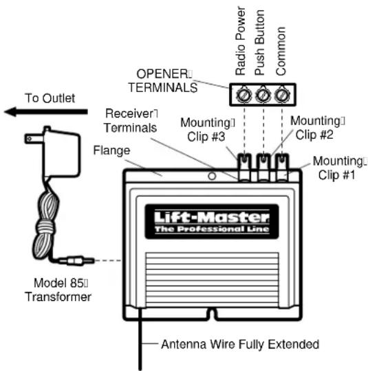
Fully extend antenna wire below bottom of case as shown.
Loosen the three terminal screws on the receiver (labeled 1, 2 and 3). Insert one end of a mounting clip under each terminal. Make sure the clips are positioned to clear the receiver flange, as shown. Do not retighten at this time.
Loosen the three terminal screws on the opener used for push button controls and radio power.
Leaving the push button bell wire in place, insert the other ends of the mounting clips under the opener terminal screws.
NOTE: If the number sequence of opener terminals doesn't match the receiver, turn the receiver around (so back is facing out) and complete the connection.
Retighten the terminal screws on opener and receiver. Reconnect power to the opener. The receiver push bar should light. If it does not, use Transformer Model 85.
MOUNTING ON RESIDENTIAL OPENERS
Use a 2 wire connection only. Attach mounting clips to receiver terminals 1 and 2, and to the opener terminals used for push button controls. Plug the transformer into the receiver as shown, and into a 120 Volt outlet.
To comply with FCC/IC rules, adjustment or modification of receiver and/or transmitter is prohibited, except for changing the code setting and replacing the transmitter battery. THERE ARE NO USER SERVICEABLE PARTS.

WARNING
Disconnect power to the garage door opener before installing the receiver.

WARNING
Children operating or playing with a garage door opener can injure themselves and others. The garage door could close and cause serious injury or death. Do not allow children to operate the push buttons or the remote control transmitters.
Install the receiver (and any additional push buttons) out of the reach of children and away from all moving parts of the door and door hardware, but where the garage door is visible.
A moving garage door could injure someone under it. Activate the opener only when the door is properly adjusted, you can see it clearly, and there are no obstructions to door travel.
text_image
To Outlet Model 85 Transformer Flange Receiver Terminals OPENER TERMINALS Radio Power Push Button Common Mounting Clip #3 Mounting Clip #2 Mounting Clip #1 Lift-Master The Professional Line Antenna Wire Fully ExtendedPage two contains wall mounting instructions and service information as well as code setting instructions.
MOUNTING RECEIVER ON GARAGE WALL
Fully extend the antenna wire below bottom of case.
Fasten the receiver to an inside garage wall with dry wall screws provided. A convenient place is alongside the service door and OUT OF THE REACH OF CHILDREN.
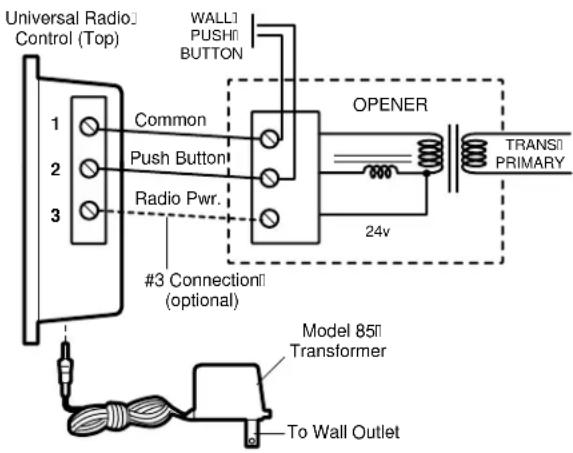
Attach one end of 3-strand bell wire (not supplied) to receiver terminals 1, 2 and 3. Connect the other end to the three opener terminals used for push button controls and radio power. Use insulated staples to secure bell wire between receiver and opener.
Reconnect power to the opener. The receiver push bar should light. If it does not, use Transformer Model 85.
NOTE: With the transformer, use a 2-wire connection only. Attach wire to receiver terminals 1 and 2 and to the opener terminals used for push button control. Plug the transformer into receiver and 120 Volt outlet as shown.
text_image
Universal Radio Control (Top) 1 Common 2 Push Button 3 Radio Pwr. #3 Connection (optional) OPENER TRANSI PRIMARY 24v Model 85II Transformer To Wall OutletSET RECEIVER TO MATCH REMOTE CONTROL(S) CODE
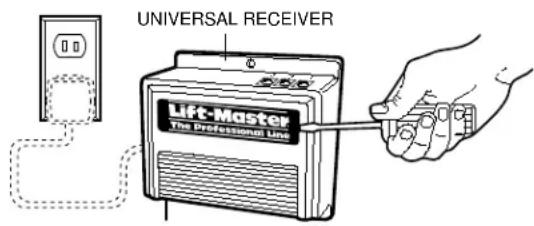
Pry open the front panel of receiver case with a coin or a screwdriver.
- Press and hold the remote control push button.
- Then press and release the "Smart" button on the receiver. The adjacent indicator light will flash once. Release the remote control push button.
The opener will now operate when the push button on either the receiver or the remote control transmitter is pressed.
Repeat Steps 1 and 2 for each remote control that will be used to operate the garage door opener.
NOTE: If the remote control push button is not held down until the receiver indicator light flashes, the receiver will not learn the code.
TO ERASE ALL REMOTE CONTROL CODES
- Press and hold the "Smart" code button on the receiver panel until the indicator light turns off (about 6 seconds). All the codes the receiver has learned will be erased.
- Repeat Steps 1 and 2 to reprogram the receiver for each remote control transmitter in use.
text_image
UNIVERSAL RECEIVER Lift-Master The Professional Line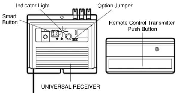
text_image
Indicator Light Smart Button Option Jumper Remote Control Transmitter Push Button UNIVERSAL RECEIVERTO SET OUTPUT DURATION

WARNING
The use of radios incorporating constant closure contacts on residential operators with fail-safe infra-red protectors is prohibited.
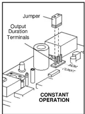
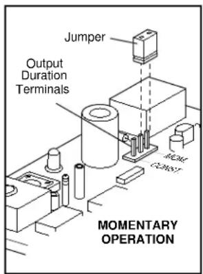
The receiver can be set for either constant or momentary closure on the output contacts. With the jumper in the "MOM" (Momentary) position, the contacts will close for 1/4 second regardless of the length of radio transmission. With the jumper in "CONST" (Constant) position, the contacts will stay closed as long as the radio continues transmitting.
The receiver is factory set at M.
text_image
Jumper Output Duration Terminals MOMENTARY OPERATION