
Santo 1544-4 iU - Kühlschrank AEG - Kostenlose Bedienungsanleitung
Finden Sie kostenlos die Bedienungsanleitung des Geräts Santo 1544-4 iU AEG als PDF.


Benutzerfragen zu Santo 1544-4 iU AEG
0 Frage zu diesem Gerät. Beantworten Sie die, die Sie kennen, oder stellen Sie Ihre eigene.
Eine neue Frage zu diesem Gerät stellen
Laden Sie die Anleitung für Ihr Kühlschrank kostenlos im PDF-Format! Finden Sie Ihr Handbuch Santo 1544-4 iU - AEG und nehmen Sie Ihr elektronisches Gerät wieder in die Hand. Auf dieser Seite sind alle Dokumente veröffentlicht, die für die Verwendung Ihres Geräts notwendig sind. Santo 1544-4 iU von der Marke AEG.
BEDIENUNGSANLEITUNG Santo 1544-4 iU AEG
ÖKO\_SANTO 1544-4
Base unit fridges that can be built-in
Dear customer,
Before placing your new refrigerator/freezer into operation please read these operating instructions carefully. They contain important information for safe use, for installation and for care of the appliance.
Please keep these operating instructions for future reference. Pass them on to possible new owners of the appliance.
Notes which are important for your safety or for the proper functioning of the appliance are stressed with a warning triangle and/or with signal words (Warning!, Caution!, Attention!). Please observe the following carefully.
This symbol guides you step by step in the operation of the appliance.
i Supplementary information regarding operation and practical applications of the appliance appear after this symbol.
Tips and notes concerning economical and environmentally sound use of the appliance are marked with the cloverleaf.
Explanations of the technical terminology used in the operating instructions can be found at the end in the section "Technical Terminology".
The operating instructions contain instructions for the correction of possible malfunctions by the user in the section "What to do if ...". If these instructions should not be sufficient, our customer service department is always available to you.
Printed on paper manufactured with environmentally sound processes. he who thinks ecologically acts accordingly ...
Content
Safety 5
Disposal 7
Appliance Packaging Information 7
Disposal of old Appliances 7
Remove transport safeguard 8
Installation 9
Installation Location 9
Installation 10
Power supply 10
Description of the appliance 11
View of the appliance 11
Prior to Initial Start-Up 11
Initial use 12
Switching off the appliance, holiday switch 14
Interior Accessories 15
Storage shelves 15
Variable door interior 15
Vegetable basket and serving tray 16
Correct Storage 16
Defrosting 16
The fridge defrosts automatically 16
Cleaning and Care 17
Energy Saving Tips 18
What to do if ... 19
Correcting Malfunctions 19
Replace light bulb 20
Content
Customer Service 21
Noises during Operation 22
Regulations, Standards, Guidelines 22
Technical Terminology 23
Guarantee Conditions 24
Installation Instructions.... 25

Safety
The safety aspects of our refrigerators/freezers comply with accepted technical standards and the German Appliance Safety Law. Nevertheless, we consider it our obligation to make you aware of the following safety information:
Intended use
- The refrigerator is intended for use in the home. It is suitable for the storing of food, at low temperature. If the appliance is used for purposes other than those intended or used incorrectly, no liability can be accepted by the manufacturer for any damage that may be caused.
- Alterations or changes to the refrigerator are not permitted for reasons of safety.
- If you use the refrigerator in a commercial application or for purposes other than the cooling of foods, please observe all valid legal regulations for your application.
Prior to initial start-up
- Check the freezer for transport damage. Under no circumstance should a damaged appliance be plugged in! In the event of damage, please contact the vendor.
Refrigerant
The refrigerant isobutane (R600a) is contained within the refrigerant circuit of the appliance, a natural gas with a high level of environmental compatibility, which is nevertheless flammable.
- During transportation and installation of the appliance, be certain that none of the components of the refrigerant circuit become damaged.
- If the refrigerant circuit should become damaged:
- avoid open flames and sources of ignition;
- thoroughly ventilate the room in which the appliance is situated.
Safety of children
- Packaging (e.g. wraps, polystyrene) can be dangerous for children. There is a risk of suffocation! Keep packaging material away from children!
- Please make old appliances unusable prior to disposal. Pull out the mains plug, cut off the mains cable, break or remove spring or bolt catches, if fitted. By doing this you ensure that children cannot lock themselves in the fridge when playing (there is risk of suffocation!) or get themselves into other dangerous situations.
- Often children cannot recognise the hazards present in household appliances. It is therefore important that you ensure adequate supervision and never let children play with the appliance!
Daily Operation
- Containers with flammable gases or liquids can leak at low temperatures. There is a risk of an explosion! Do not store any containers with flammable materials such as, for example, spray cans, fire extinguisher refill cartridges etc in the refrigerator/freezer.
- Do not operate any electrical appliances in the refrigerator/freezer (e.g. electric ice cream makers, mixers etc.).
- Before cleaning the appliance, always switch off the appliance and unplug it, or pull the house fuse or switch off the circuit breaker.
- When unplugging always pull the plug from the mains socket, do not pull on the cable.
In case of malfunction
- If the a malfunction occurs on the appliance, please look first in the "What to do if ..." section of these instructions. If the information given there does not help, please do not perform any further repairs yourself.
- Refrigerators/freezers may only be repaired by qualified service engineers. Improper repairs can give rise to significant hazards. If your appliance needs repairing, please contact your specialist dealer or our Customer Service.
Disposal
Appliance Packaging Information
All materials are environmentally sound! They can be dumped or burned at an incinerating plant without danger!
About the materials: The plastics can be recycled and are identified as follows:
PE< for polyethylene, e.g. the outer covering and the bags in the interior.
PS< for polystyrene foam, e.g. the pads, which are all free of chloro-fluorocarbon.
The carton parts are made from recycled paper and should be disposed of at a waste-paper recycling collection location.
Disposal of old Appliances
For environmental reasons, refrigeration appliances must be disposed of properly. This applies to your old appliance, and – at the end of its service life – for your new appliance as well.

Warning! Before disposing of old appliances make them inoperable. Remove plug from mains, sever the power cable, remove or destroy any snap or latch closures. This eliminates the danger that playing children lock themselves into the appliance (danger of suffocation!) or place themselves into other life-endangering situations.
Disposal:
- The appliance may not be disposed of with domestic waste or bulky refuse.
- The refrigerant circuit, especially the heat exchanger at the back of the appliance, may not be damaged.
• Information concerning collection schedules or locations can be obtained from the local disposal authorities or town hall.
Remove transport safeguard
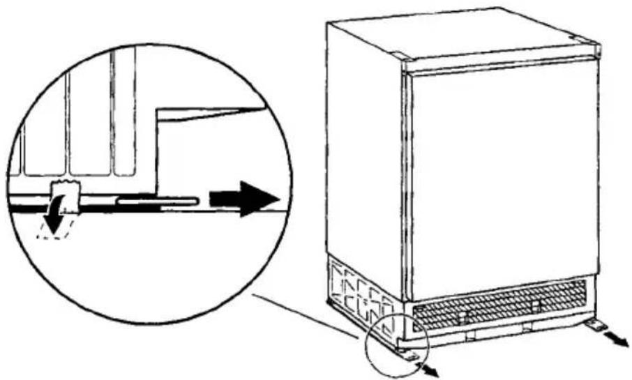
The appliance and the interior fittings are protected for transport.

Pull off the adhesive tape on the left and right side of the door.

You can remove any remnants of adhesive using white spirit.

Remove all adhesive tape and packing pieces from the interior of the appliance.

On the inside of the door, remove the protection from the seal.

Remove the transport protection pieces from the rails and pull off the adhesive tape.
natural_image
Line drawing of a refrigerator with airflow direction and component details (no text or symbols)Installation
Installation Location
The appliance should be set up in a well ventilated, dry room.
Energy use is affected by the ambient temperature.
The appliance should therefore
- not be exposed to direct sunlight;
- not be installed next to radiators, cookers or other sources of heat;
- only be installed at a location whose ambient temperature corresponds to the climate classification, for which the appliance is designed.
The climate classification can be found on the serial plate, which is located at the left on the inside of the appliance.
The following table shows which ambient temperature is correct for each climate classification:
| Climate classification | for an ambient temperature of |
| SN | +10 to +32 °C |
| N | +16 to +32 °C |
| ST | +18 to +38 °C |
| T | +18 to +43 °C |
If installation next to a source of heat is unavoidable, the following minimum clearances must be maintained at the sides of the appliance:
- for electric cookers 3 cm;
- for oil and coal fired ranges 30 cm.
If these clearances cannot be maintained a heat insulating pad is required between the cooker and the refrigeration appliance.
If the refrigeration appliance is installed next to another refrigerator or freezer a clearance of 5 cm at the sides is required, in order to prevent the formation of condensation on the outside of the appliance.
Installation
See installation instructions supplied.
Please check whether, after installing your appliance and especially after rehingeing the door, the door seal seals right round. An untight door seal may lead to heavy frosting and thereby to a higher power consumption (see also "What to do if...").
Power supply
A correctly installed, earthed socket is required for the electrical supply. The supply must have a fuse rating of at least 10 Amps.
If the socket is not accessible once the appliance is built in, the electrical installation must include suitable means of isolating the appliance from the mains (e.g. fuse, cut-out, current trip or similar with a minimum contact separation of 3 mm).
Before initial start-up, refer to the appliance serial plate to ascertain if supply voltage and current values correspond with those of the mains at the installation location.
e.g.: AC 220 ... 240 V 50 Hz or
220 ... 240 V \~50 Hz
(i.e. 220 to 240 volts alternating current, 50 Hertz)
The rating plate is inside the appliance on the left.
The mains cable may only be changed by a qualified electrician. If your appliance needs repairing, please contact our Customer Service.
Description of the appliance
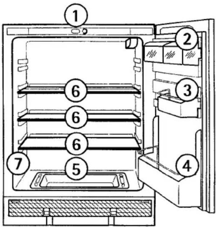
View of the appliance
text_image
Diagram of a refrigerator interior with numbered compartments for identification① Temperature regulator and light switch
② Butter/cheese compartments with flap and egg storage insert
③ Door storage compartment with retaining rail
④ Bottle shelf
⑤ Vegetable basket with serving tray
⑥ Storage shelves
⑦ Rating plate
Prior to Initial Start-Up

Please clean the appliance interior and all accessories prior to initial start-up (see section: "Cleaning and Care").
Initial use
Important! Only use the appliance when built-in!

Plug the mains plug into the mains socket. When the door is opened the interior lighting comes on.
text_image
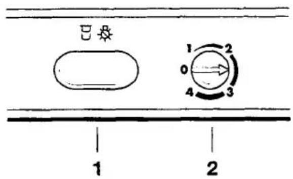
1 21 Light switch
2 Temperature regulator and ON/OFF switch
The temperature regulator is also the ON/OFF switch.
The large oval switch beside the temperature regulator is the light switch. When the door is opened and closed, the light switch switches the interior lighting on and off.
A coin in needed to turn the temperature regulator. This makes it is more difficult to change the temperature setting accidentally (child protection).
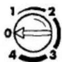
The temperature regulator setting shown means: Refrigeration off.
Turn in the direction of "1":
Refrigeration on, the compressor starts and then runs automatically. The green pilot light illuminates.
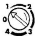
Position "1" means:
Highest interior temperature (warmest setting)
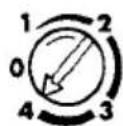
Position "4" means:
Lowest interior temperature (coldest setting)
The following effects are of significance in respect of the interior temperature:
- Ambient temperature;
- Quantity and temperature of the food stored;
- Frequency with which the door is opened and how long it is left open.
The following temperature settings can therefore only be considered as recommendations that may well need to be adapted to suit your particular situation.
Recommended settings:
For normal use: position "1" to "2";
For lower temperatures: position "2' to "3".

Turn the temperature regulator to the desired setting with the aid of a coin.
The compressor starts and then runs automatically.
Important!
High ambient temperatures (e.g. on hot summer days) and a cold setting on the temperature regulator (position "3" to "4") can cause the compressor to run continuously.
Reason: when the ambient temperature is high, the compressor must run continuously to maintain the low temperature in the appliance. The fridge will not be able to defrost since automatic defrosting of the fridge is only possible when the compressor is not running (see also "Defrosting" section). The result is the build up of a thick layer of frost on the fridge rear wall.
If this happens, turn the temperature regulator back to a warmer setting (position "2" to "3"). At this setting the compressor will be switched on and off as usual and automatic defrosting will recommence.
Switching off the appliance, holiday switch
To switch off the appliance, turn the temperature regulator to position "0".
If the door is to left open for an extended period, switch off the interior lighting by pulling out the oval light switch (holiday switch).
The light switch is pressed in again as soon as the door is closed. The next time the door is opened, the interior lighting is switched on by the light switch as normal.
If the appliance is not going to be used for an extended period:
Switch off the appliance by turning the temperature regulator to position "0".
Remove the mains plug or switch off or turn out the circuit breaker or fuse.
Leave the door open to avoid the build up of odours.
Interior Accessories
Storage shelves
Your appliance is equipped with two full size and two half size glass storage shelves.
If possible, please slide one of the full size glass storage shelf into the lowest set of guides, above the vegetable basket and the serving tray.
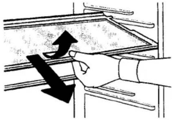
The height of the storage shelves can be adjusted:
To do this pull the storage shelf forward until it can be swivelled upwards or downwards and removed.
Please do the same in reverse to insert the shelf at a different height.
Storing tall items:
Slide the half size glass storage shelf in the upper or middle level to the rear. By this means you will gain space to place tall items on the storage shelf below.
natural_image
Hand holding a shelf with a large black arrow pointing downward (no text or symbols visible)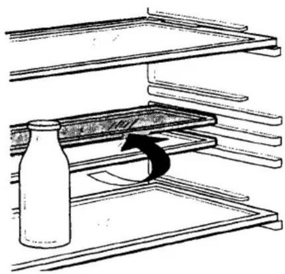
natural_image
Diagram of a bottle being placed on a tray with an arrow indicating rotation (no text or symbols present)Variable door interior
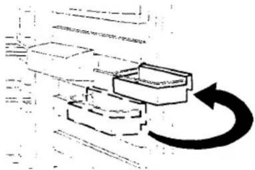
Depending on your requirements, the storage compartments on the door can be removed sideways and repositioned in a different place.
natural_image
Diagram of a mechanical or electrical component with a curved arrow indicating rotation or cycle (no text or symbols present)Vegetable basket and serving tray
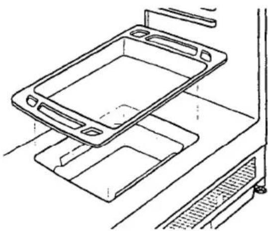
There is a vegetable basket in the base of the appliance, this is covered with a serving tray made from transparent plastic.
natural_image
Technical line drawing of a mechanical tray with mounting bracket (no text or symbols)Correct Storage
For physical reasons, there are different temperature regions in the fridge. The coldest region is on the lowest storage shelf. Warmer regions are the top storage shelf, the vegetable basket and the storage compartments on the door.
Tip: Food in the fridge should always be covered or packaged, to prevent drying and tainting of other food.
The following are suited for packaging:
- Polyethylene airtight bags and wraps;
- Plastic containers with lids;
- Special plastic covers with elastic;
- aluminium foil.
Defrosting
The fridge defrosts automatically
The rear wall of the fridge covers with frost when the compressor is running, and defrosts when the compressor is off.
The water from the thawing frost is collected in the drain channel on the rear of the fridge, feed through the drain hole into the collection compartment in the base, and then evaporated.
Cleaning and Care
For hygienic reasons the appliance interior, including interior accessories, should be cleaned regularly.

Warning!
- The appliance may not be connected to the mains during cleaning. Danger of electrical shock! Before cleaning switch the appliance off and remove the plug from the mains, or switch off or turn out the circuit breaker or fuse.
- Never clean the appliance with a steam cleaner. Moisture could accumulate in electrical components, danger of electrical shock! Hot vapours can lead to the damage of plastic parts.
- The appliance must be dry before it is placed back into service.
Attention!
- Ethereal oils and organic solvents can attack plastic parts, e.g.
- lemon juice or the juice from orange peals;
- butyric acid;
- cleansers which contain acetic acid.
Do not allow such substances to come into contact with appliance parts. - Do not use any abrasive cleansers.
Remove the food from the refrigerator. Store it in a cool place, well covered.
Switch the appliance off and remove the plug from the mains, or switch off or turn out the circuit breaker or fuse.
Clean the appliance and the interior accessories with a cloth and lukewarm water. Commercially available dish washing detergents may also be used.
After cleaning wipe with fresh water and rub dry.
Check the water drain hole on the rear wall of the fridge. Clear a bloked drain hole with the aid of a piece of wire.
After everything is dry place appliance back into service.

Energy Saving Tips
- Do not install the appliance near cookers, radiators or other sources of warmth. High ambient temperatures cause longer, more frequent operation of the compressor.
- Ensure sufficient air circulation and exhaust at the appliance base and at the back wall of the appliance. Never cover air vent openings.
- Do not place warm foods into the appliance. Allow warm foods to cool first.
- Only leave door open as long as necessary.
- Do not set temperature any colder than necessary.
What to do if ...
Correcting Malfunctions
A malfunction may be caused by only a minor fault that you can rectify yourself using the following instructions. Do not perform any other work on the appliance if the following information does not provide assistance in your specific case.

Warning! Repairs to refrigerators/freezers may only be performed by qualified service engineers. Improper repairs can give rise to significant hazards for the user. If your appliance needs repairing, please contact your specialist dealer or our Customer Service.
| Malfunction | Possible Cause | Remedy |
| Appliance does not work. | Appliance is not switched on. | Switch on the appliance. |
| Mains plug is not plugged in or is loose. | Insert mains plug. | |
| Fuse has blown or is defective. | Check fuse, replace if necessary. | |
| Socket is defective. | Mains malfunctions are to be corrected by an electrician. | |
| Appliance cools too much. | Temperature is set too cold. | Turn the temperature regulator to a warmer setting temporarily. |
| The food is too warm. | Temperature is not properly adjusted. | Please look in the "Initial use" section. |
| Door was open for an extended period. | Open the door only as long as necessary. | |
| A large quantity of warm food was placed in the appliance within the last 24 hours. | Turn the temperature regulator to a colder setting temporarily. | |
| The appliance is near a heat source. | Please look in the "Installation location" section. | |
| Interior lighting does not work. | Light bulb is defective. | Please look in the "Replace light bulb" section. |
| Heavy build up of frost, possibly also on the door seal. | Door seal is not air tight (possibly after changing over the hinges). | Carefully warm the lea-king sections of the door seal with a hair dryer (not hotter than approx. 50 °C). At the same time shape the warmed door seal by hand such that it sits correctly. |
| Unusual noises. | Appliance is not level. | Readjust the feet. |
| The appliance is touching the wall or other objects. | Move the appliance slightly. | |
| A component, e.g. a pipe, on the rear of the appliance is touching another part of the appliance or the wall. | If necessary, carefully bend the component out of the way. | |
| The compressor does not start immediately after changing the temperature setting. | This is normal, no error has occurred. | The compressor starts after a period of time. |
| Water on the floor or on storage shelves. | Water drain hole is blok-ked. | See the "Cleaning and Care" section. |
Replace light bulb

Warning! Danger of electrical shock! Before replacing the light bulb switch appliance off and remove the mains plug, or switch off or turn out the circuit breaker or fuse.
Light bulb specifications: 220-240 V, max. 15 W, socket: E 14

To switch off the appliance, turn the temperature regulator to position "0".

Unplug the mains plug.
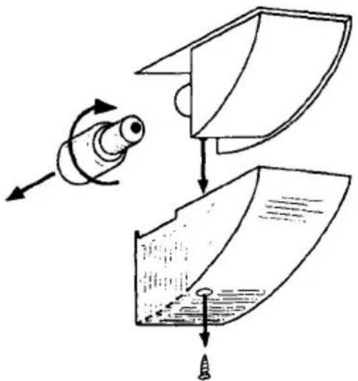
To change the light bulb, undo the cross head screw and remove the light bulb cover downwards.
Change the defective light bulb.
Refit the light bulb cover and the cross head screw.
natural_image
Diagram showing a mechanical assembly with rotating components and a folded sheet (no text or symbols)Customer Service
If you cannot find the remedy for a malfunction in these operating instructions, please contact your dealer or our customer service department. Addresses and telephone numbers are listed in the accompanying booklet "Guarantee Conditions/Customer Service Locations".
Selective ordering of replacement parts can save unnecessary travel and costs. For this reason always provide the following appliance information:
This information can be found on the serial plate in the interior at the
- Model Name
- Model Number (PNC)
- Serial Number (S-No.)
text_image
Scanned document with dense text blocks and a horizontal bar, likely a form or template sheetleft of the appliance. We recommend that you enter this information here, so that it is handy if needed.
If the temperature display should indicate an error (F1, F2, etc.), inform customer service of the displayed error.
Note: The customer bears the costs of unjustified customer service calls even during the guarantee period.
Noises during Operation
The following noises are characteristic of refrigeration appliances:
- Clicks
Whenever the compressor switches on or off, a click can be heard.
• Humming As soon as the compressor is in operation, you can hear it humming.
- Bubbling/Splashing When refrigerant flows into thin tubes, you can hear bubbling or splashing noises. Even after the compressor has been switched off, this noise can be heard for a short time.
Regulations, Standards, Guidelines
This appliance was designed for household use and was manufactured in accordance with the appropriate standards. The necessary measures in accordance with appliance safety legislation regulations (GSG), accident prevention regulations for refrigeration appliances (VBG 20) and the regulations of the German Society of Electrical Engineers (VDE) were observed in the manufacture of this appliance. The refrigerant circuit has been checked for leaks.
CE This appliance is in accordance with the following EU guidelines: - 73/23/EWG dated 19 February 1973 - low voltage guidelines. - 89/336/EWG dated 3 May 1989 (including guideline change notice 92/31/EWG) - EMV guideline
Technical Terminology
• Refrigerant Liquids that can be used to a generate a cooling effect are known as refrigerants. They have a relatively low boiling-point, indeed so low, that the warmth from the food stored in the fridge or freezer can cause the refrigerant to boil and vaporise.
- Refrigerant Circuit Closed circulation system that contains the refrigerant. The refrigerant circuit comprises primarily of an evaporator, a compressor, a condenser and pipe work.
- Evaporator The refrigerant is evaporated in the evaporator. Similar to all other liquids, refrigerant requires heat to evaporate. This heat is removed from the interior of the appliance, as a result the interior is cooled. The evaporator is therefore located inside the appliance or placed in foam immediately behind the inner wall and thus not visible.
- Compressor The compressor looks like a small drum. It is driven by a built-in electric motor and is mounted on the base of the appliance at the rear. The task of the compressor is to draw in vaporised refrigerant from the evaporator, to compress it, and to pass it on to the condenser.
- Condenser The condenser normally has the form of a grid. The refrigerant compressed in the compressor is liquefied in the condenser. During this process, heat is released to the surrounding air at the surface of the condenser. The condenser is mounted on the base of the appliance.
Guarantee Conditions
For general enquiries or information regarding AEG appliances contact:
Customer Services Department
AEG Domestic Appliances Ltd.
PO Box 47, Newbury
Berkshire RG14 5XL
Tel: 01635 572700 Fax: 01635 42970
To book a service call or purchase spare parts, contact AEG Service Force.
Tel: 0990 929929
When contacting AEG Service Force, please give:
-Your name
- Details of the fault
- Address with Postcode
- Name and model of the appliance
- Telephone number
- E number (9 digit number found on the rating plate).
Guarantee Conditions
AEG offer the following guarantee to the first purchaser of this appliance:
- The guarantee is valid for 12 months commencing when the appliance is handed over to the first retail purchaser, which must be verified by purchase invoice or similar documentation.
The guarantee does not cover commercial use. - The guarantee covers all parts or components which fail due to faulty workmanship or faulty material. The guarantee does not cover appliances where defects or poor performance are due to misuse, accidental damage, neglect, faulty installation, unauthorised modification or attempted repair, commercial use or failure to observe requirements and recommendations set out in the instruction book.
This guarantee does not cover such parts as light bulbs, removable glassware, dust bags or filters. - Should guarantee repairs be necessary the purchaser must inform the nearest customer service office (AEG's service or authorised agent). AEG reserves the right to stipulate the place of repair (i.e. the customer's home, place of installation or AEG workshop).
- The guarantee or free replacement includes both labour and materials.
5: Repairs carried out under guarantee do not extend the guarantee period for the appliance. Parts removed during guarantee repairs become the property of AEG. - The Purchaser's statutory rights are not affected by this guarantee.
European Guarantee
If you should move to another country within Europe then your guarantee moves with you to your new home subject to the following qualifications:
- The guarantee starts from the date you first purchased your product.
- The guarantee is for the same period and to the same extent for labour and parts as exists in the new country of use for this brand or range of products.
- This guarantee relates to you and cannot be transferred to another user.
- Your new home is within the European Community (EC) or European Free Trade Area.
- The product is installed and used in accordance with our instructions and is only used domestically, i.e. a normal household.
- The product is installed taking into account regulations in your new country.
Before you move please contact your nearest Customer Care centre, listed below, to give them details of your new home. They will then ensure that the local Service Organisation is aware of your move and able to look after you and your appliances.
France Senlis +33 (0) 3 44 62 29 29
Germany Nurnberg +49 (0) 911 3 23 26 00
Italy Pordenone +39 (0) 1678 4 70 53
Sweden Stockholm +46 (0) 8 738 79 10
UK Newbury +44 (0) 1635 57 27 00
AEG (UK) Limited, 217 Bath Road, Slough, Berkshire SL1 4AW, Tel. (01753) 872506
Installation Instructions
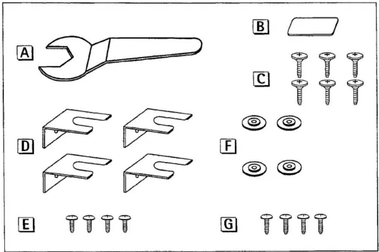
Installation parts supplied
text_image
A B C D E F G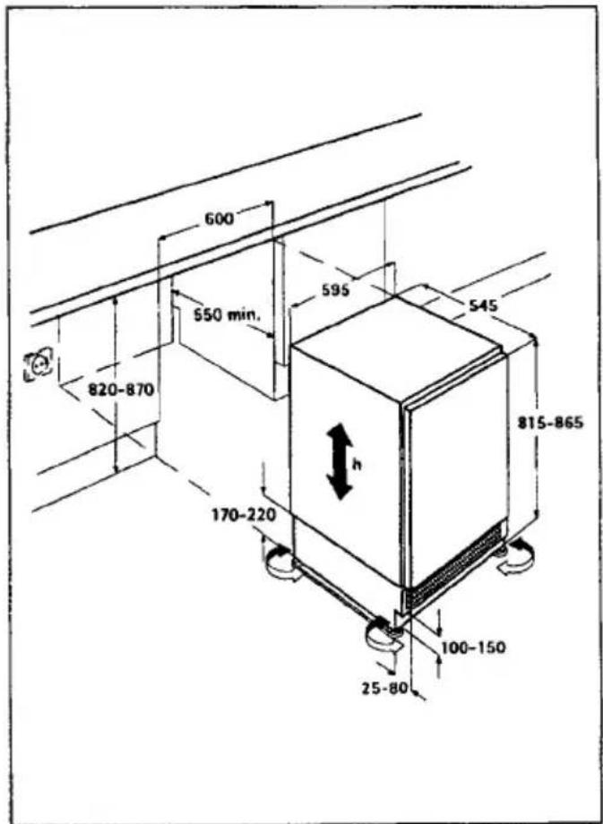
text_image
600 550 min. 595 545 820-870 170-220 h 815-865 100-150 25-80Dimensioned drawings
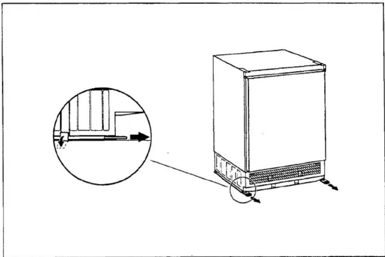
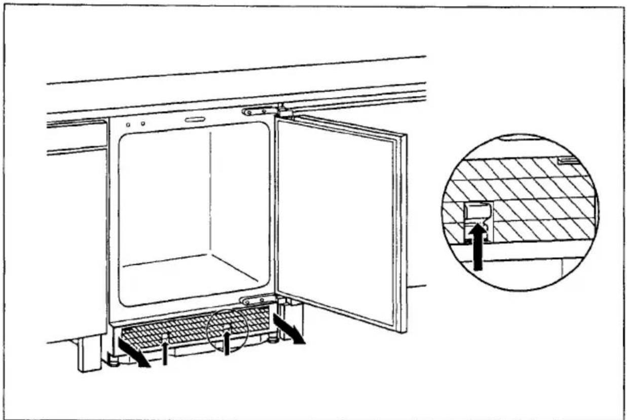
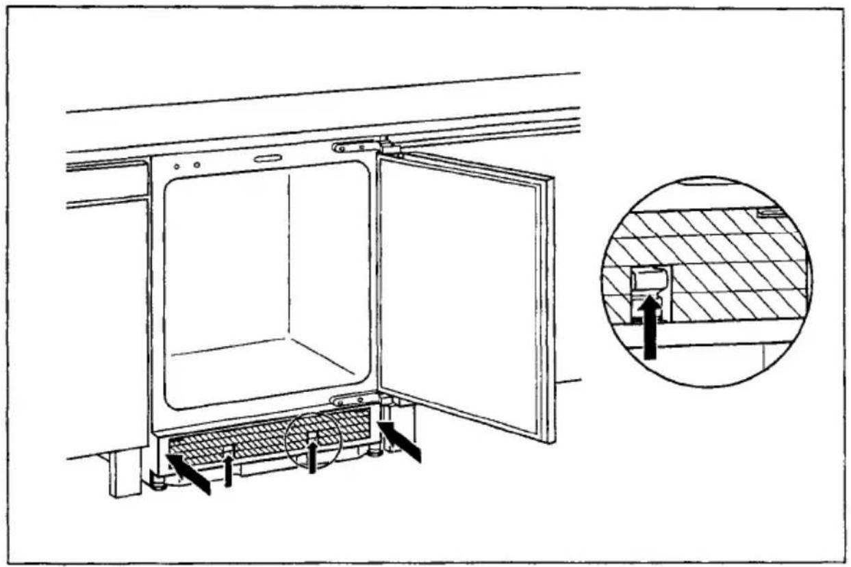
Remove transport safeguard
natural_image
Line drawing of a refrigerator with an inset showing airflow or ventilation system (no text or symbols)Removing covering and adjusting strips
text_image
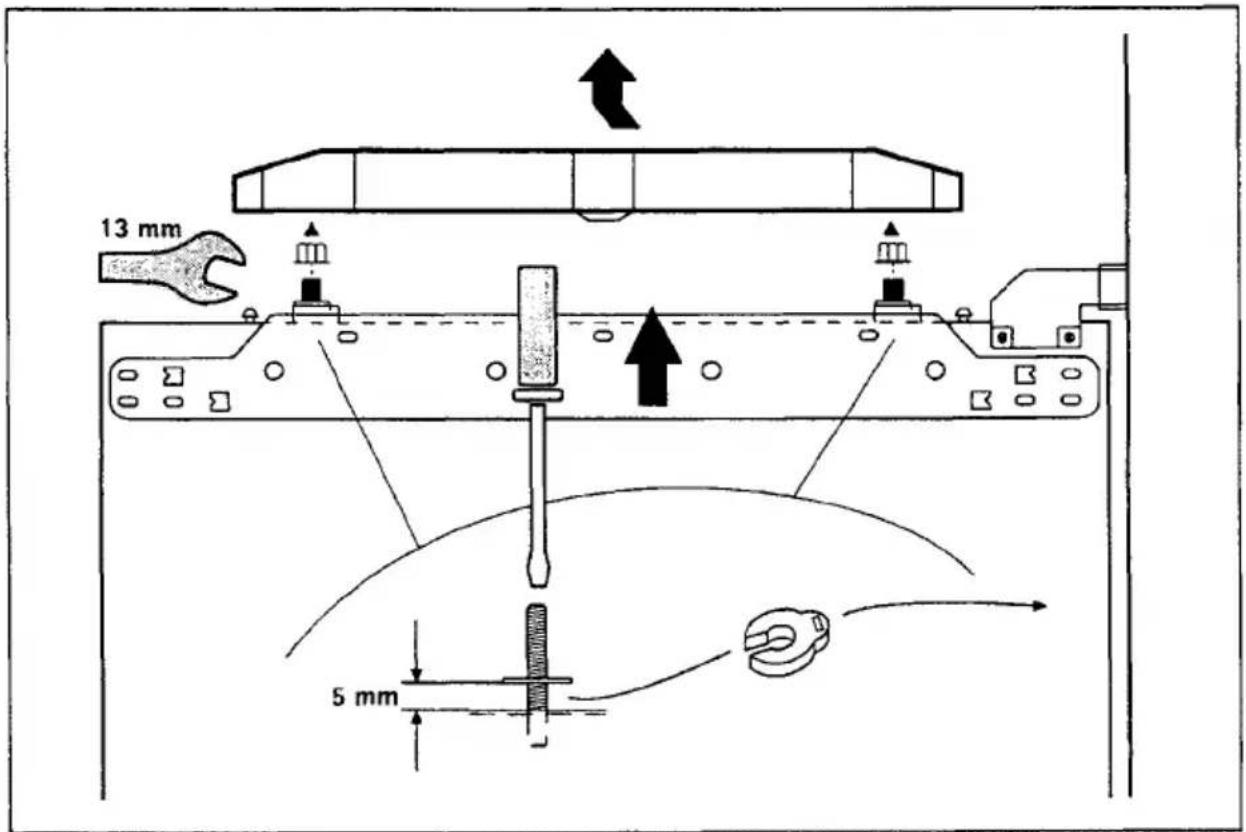
13 mm 5 mmRemoving base blind
natural_image
Technical line drawing of a door opening with internal components, showing a magnified inset of the interior wall (no text or symbols)Rehingeing the door (where necessary)
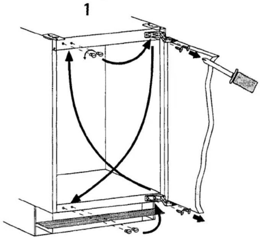
text_image
12
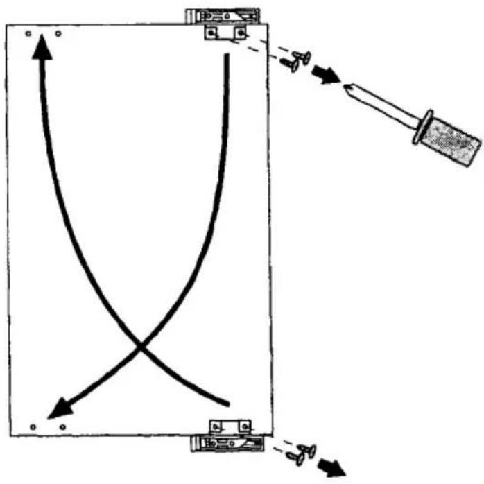
text_image
Diagram showing a device with curved and straight lines, labeled with directional arrows and a tool pointing to it.3
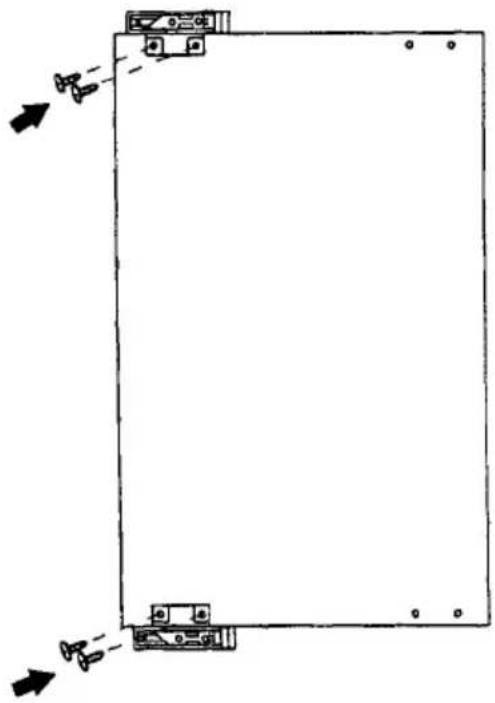
natural_image
Pure technical diagram of a rectangular frame with directional arrows indicating movement or force (no text or symbols)1
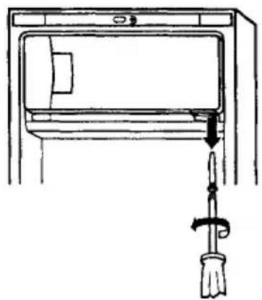
natural_image
Simple line drawing of a door handle with a trowel and lever (no text or symbols)2
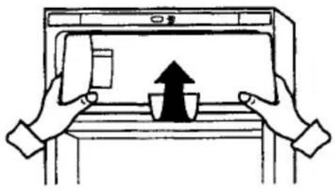
natural_image
Illustration of two hands holding a tablet with an upward arrow and cup, no text or symbols present3
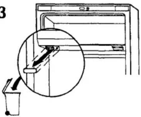
text_image
34
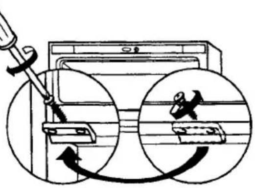
natural_image
Diagram of a washing machine with two circular insets showing internal components (no text or symbols)5
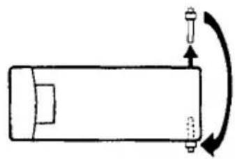
natural_image
Simple line drawing of a rectangular object with a curved arrow indicating rotation or motion (no text or symbols)6
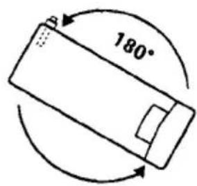
text_image
180°7
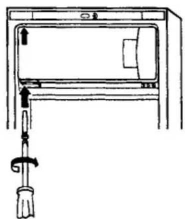
natural_image
Line drawing of a door handle assembly with a tool inserted (no text or symbols)8
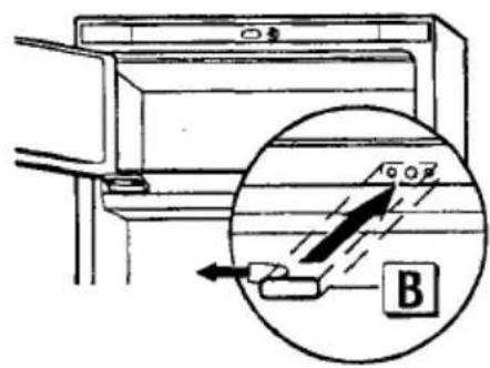
text_image
Diagram showing a device with an inset magnified view labeled B, highlighting internal components or flow direction.
natural_image
Line drawing of a simple indoor air conditioner unit with cooling unit and heating element (no text or symbols)Push appliance into place
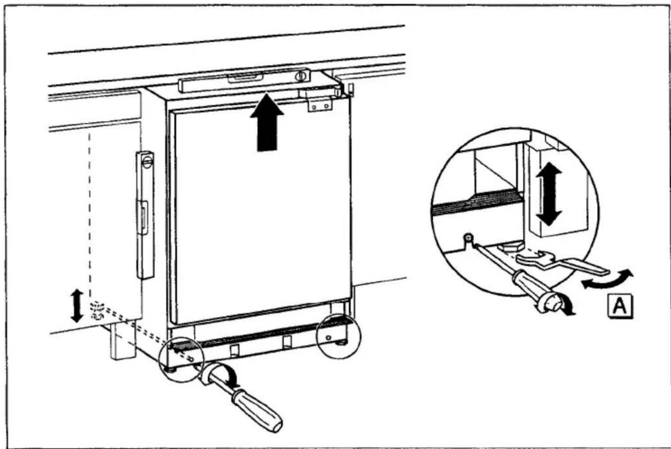
Adjust height
text_image
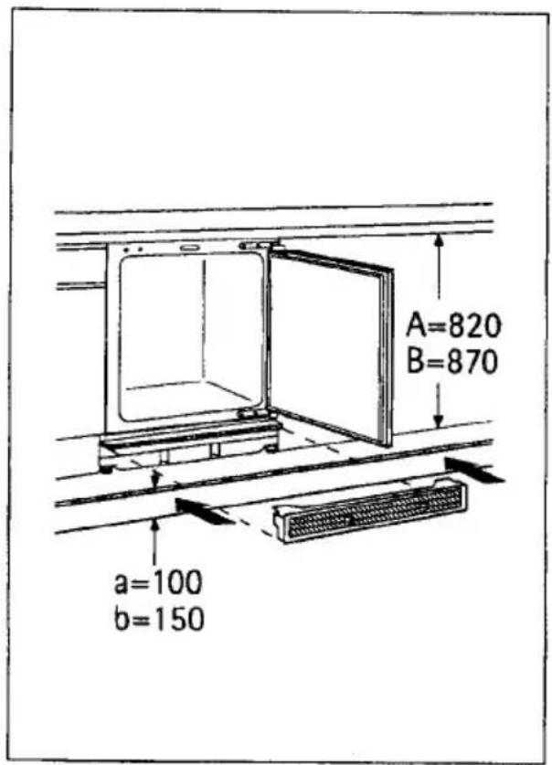
Technical diagram showing a mechanical device with directional arrows and a magnified inset illustrating the internal mechanism.Adjusting base
text_image
A=820 B=870 a=100 b=150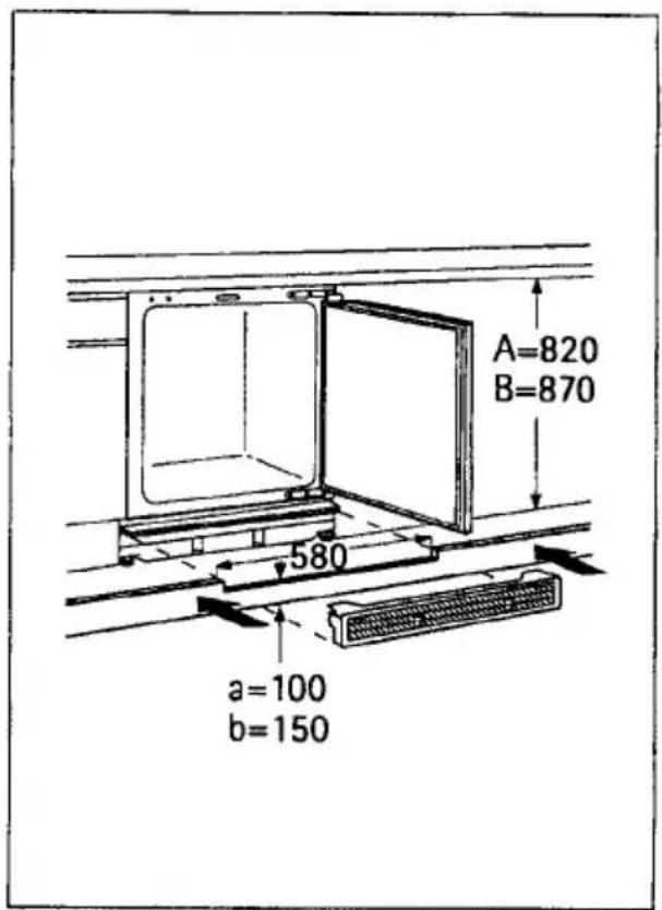
text_image
A=820 B=870 580 a=100 b=150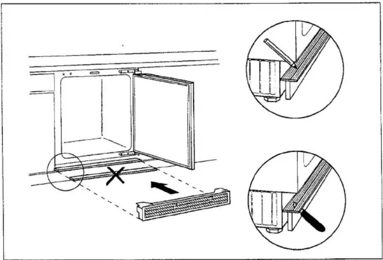
text_image
Technical diagram illustrating a door opening mechanism with labeled components and crosshair indicators for assembly or repair.Placing the base blind
natural_image
Technical line drawing of a door opening with internal components and a magnified inset showing a tiled wall structure (no text or symbols)Mounting furniture door
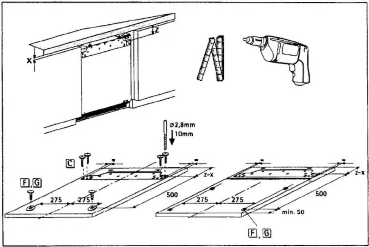
text_image
x z Ø2,8mm 10mm C F,G 275 275 500 275 275 min. 50 F,G z-x 500 z-x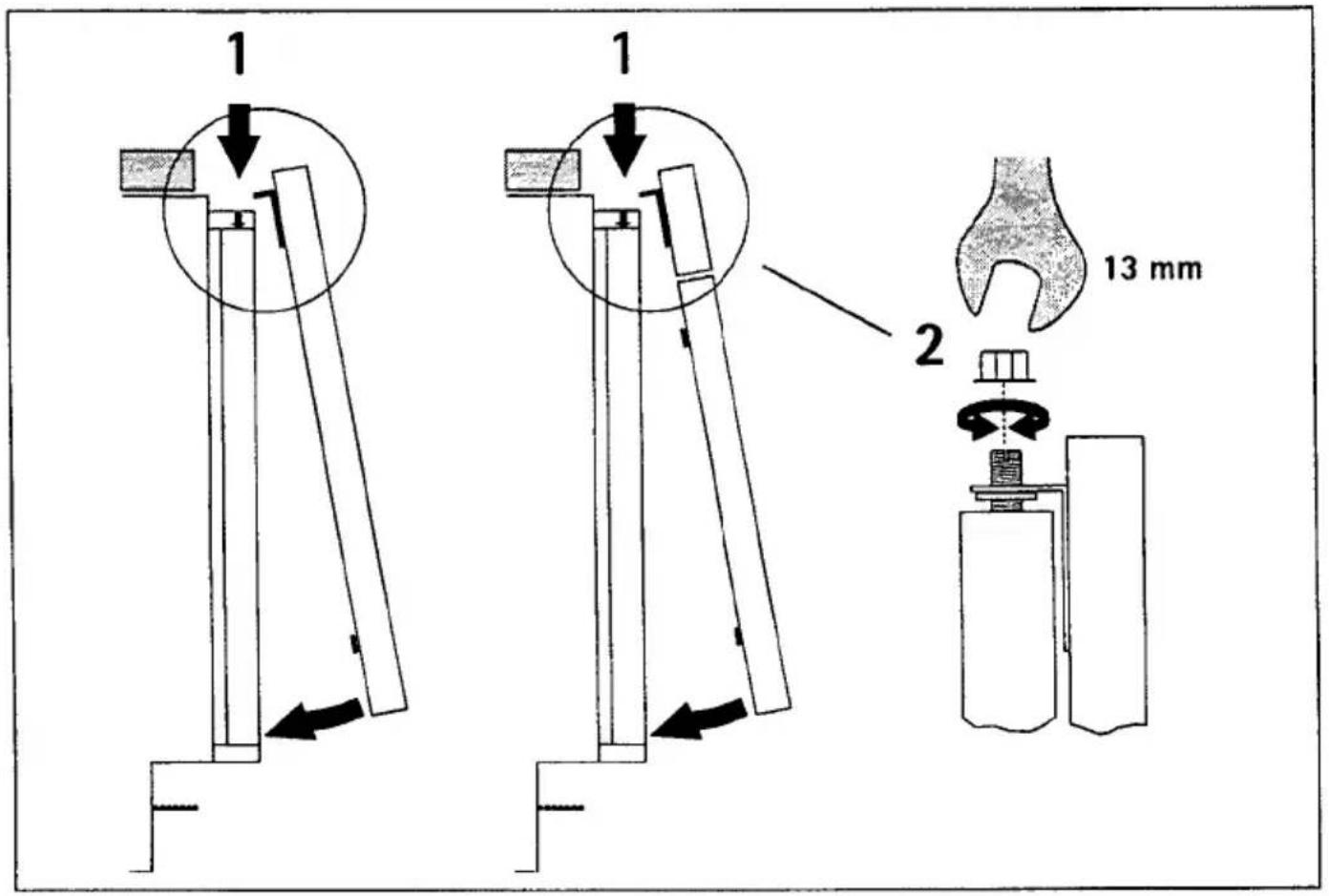
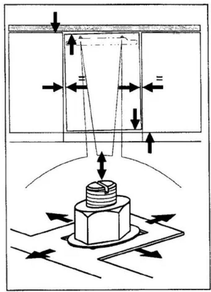
text_image
Technical diagram showing mechanical assembly with directional arrows and a central bolted component, likely illustrating a cutting or machining process.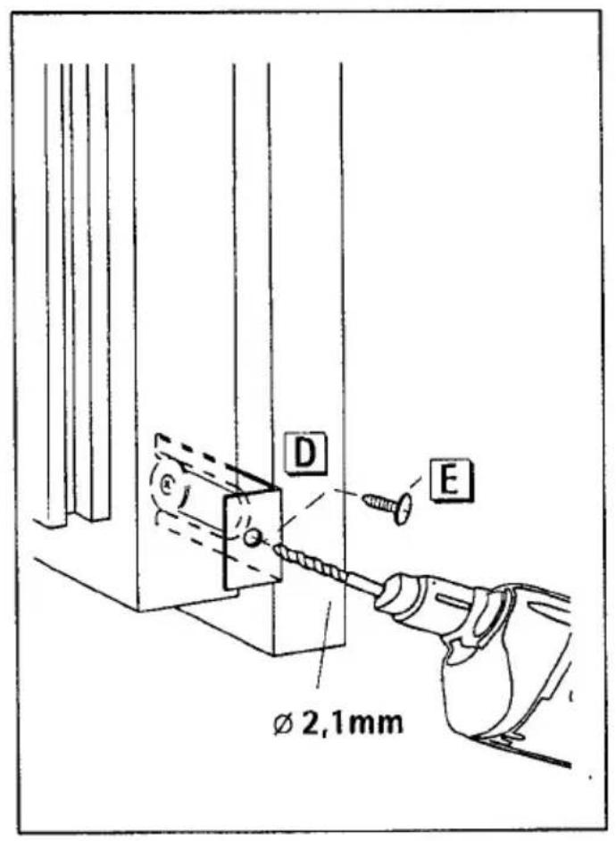
text_image
D E Ø 2,1mmScrew appliance into place
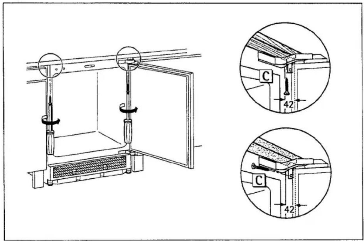
text_image
Technical diagram showing mechanical assembly with labeled components and dimensional annotationsPlacing the covering strip
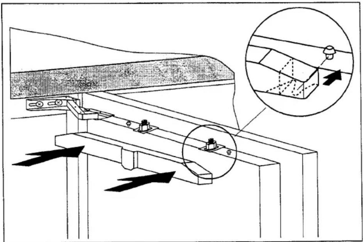
natural_image
Technical diagram of a conveyor belt system with directional arrows indicating flow or movement, and an inset magnified view showing a 3D mesh structure (no text or symbols present)AEG Hausgeräte AG
Postfach 1036
D-90327 Nürnberg 1
© Copyright by AEG
H 271 284 400-01-0198
AEG Domestic Appliances Ltd
Customer Care Department
55-77 High Street
Slough
Berkshire SL1 1DZ
Telephone: 08705 350350