
Santo 1732 TK - Kühlschrank AEG - Kostenlose Bedienungsanleitung
Finden Sie kostenlos die Bedienungsanleitung des Geräts Santo 1732 TK AEG als PDF.


Benutzerfragen zu Santo 1732 TK AEG
0 Frage zu diesem Gerät. Beantworten Sie die, die Sie kennen, oder stellen Sie Ihre eigene.
Eine neue Frage zu diesem Gerät stellen
Laden Sie die Anleitung für Ihr Kühlschrank kostenlos im PDF-Format! Finden Sie Ihr Handbuch Santo 1732 TK - AEG und nehmen Sie Ihr elektronisches Gerät wieder in die Hand. Auf dieser Seite sind alle Dokumente veröffentlicht, die für die Verwendung Ihres Geräts notwendig sind. Santo 1732 TK von der Marke AEG.
BEDIENUNGSANLEITUNG Santo 1732 TK AEG
SANTO 1530TK/1550TK/1534TK 1730TK/1732TK/1734TK/1740TK 1750TK/1930TK
Automatic Table Top Refrigerators
Operating Instructions
GB
Contents Page
Illustration pages (please unfold) 2-6
General instructions, Choice of location 15
Rehingeing the door 16
Your freezer needs air 16
Changing the freezer compartment door 17
Decorating the appliance door 17
Matching with a variable worktop 17
Voltage and current 18
Starting up and temperature regulation 18/19
Correct storage 19
Defrosting, cleaning, and care 19/20
Faults and servicing 20
Minor repairs 20
Hints on correct use and energy-saving 20
natural_image
Technical diagram of a mechanical assembly with two components and dimension lines (no text or symbols)1
text_image
D C B A 10mm4
text_image
B2
text_image
E 10mm5
text_image
10mm A3
text_image
Diagram illustrating pressure forces (P) and shear force (T) acting on a structural element with directional arrows indicating flow or force.6
text_image
A 10 mm7
text_image
A B10
text_image
B C D F A 180° E8
text_image
A/B 93-103 570 200 cm² C 550 10511a
text_image
A B G A B9
natural_image
Line drawing of a kitchen counter with a labeled component 'D' on the ceiling (no text or symbols beyond label)11b
text_image
Technical diagram showing two mechanical assembly steps with labeled components A and a spring attached to a bracket.12
text_image
Technical diagram showing a mechanical assembly with labeled components and angular measurement indicators15
natural_image
Illustration of a hand holding a tool near a window, with no visible text or symbols13
text_image
Technical diagram of a mechanical assembly with labeled parts A, B, and C, showing directional arrows and component alignment.16
natural_image
Illustration of hands holding a rectangular object with a shaded pattern, no text or symbols present14
text_image
533 ±0.5 781 ±0.517
text_image
Technical diagram of a device with numbered components and labeled parts, likely illustrating a mechanical or electronic assembly.20
text_image
585 x 0.5 781 x 0.518
text_image
5mm21
text_image
710 ±0.5 585 ±0.519
text_image
max.16 A 8 A 822

text_image
130 30023
text_image
AEG SANSO 1 2 3 4 5 6 7 827
text_image
1 2 3 4 5 6 7 8 9 10 11 12 13 14 15 16 17 18 19 20 21 2224 / 25
natural_image
Illustration of a hand holding a tablet with arrows indicating flow or movement (no text or symbols)28a
text_image
AEG 1 7 1 7 2 6 2 6 5 4 326
natural_image
Line drawing of a hand holding a shelf with a black arrow pointing to the tray (no text or symbols)28b
IMPORTANT!
If the refrigerator you have purchased is replacing an older model still fitted with a snap catch or lock, you should render this lock unserviceable before throwing the appliance away or putting it out for environment-friendly refuse collection
In this way you can prevent children locking themselves in when playing and thus endangering their lives.
Please make sure that the pipelines of your refrigerator are not damaged before collection for environment-friendly disposal.
Appliance Packaging Information
All used materials are environmentally compatible! They can be safely disposed of or burnt in a refuse incinerator!
Regarding the materials: the plastics can also be recycled and are marked as follows:
PE for polyethylene e.g. as used in the outer wrapping and bags inside
PS for polystyrene foam e.g. as used in the packing; this material is basically CFC-free
The cardboard parts are made of waste paper and should be put back into the waste paper collection system.
General instructions
You have just purchased a home refrigerator which has been produced according to the standards applicable to these appliances.
During manufacture, the necessary measures have been taken as required by the Appliance Safety Act (GSG), the Accident Prevention Regulations for Refrigerating Installations (VBG 20), and the Specifications of the Institute of German Electrical Engineers (VDE).
The refrigeration circuit has been checked for leakage. The appliance is radio-interference suppressed in accordance with EEC Directive 82/499/EEC as well as with the Standard relating to the Retroactive Effect of the Mains Supply EN 60 555 Parts 1-3/DIN VDE 0838 Parts 1-3, June 1987.
Before starting up, we recommend you to read the following Operating Instructions, since only by doing so can you benefit from all the advantages offered by your refrigerator.
These Operating Instructions are intended for several technically comparable models with different equipment. Please only follow the instructions corresponding to your appliance version.
Please unfold the illustration pages on the cover to enable you to compare the text and pictures alongside.
Removing the adhesive tapes
The door is secured to the housing with adhesive tapes. Remove any adhesive tape residues with a suitable petroleum-based cleansing agent.
Commercial use
Should you use your home refrigerator commercially or for purposes other than refrigeration of food and drinks, you must observe the legal requirements applicable to your area.
Choice of location
Your refrigerator should be installed in a well-ventilated, dry room.
Ambient temperature has an effect on the power consumption of the unit. The appliance should therefore:
- not stand in the direct sunshine, or close to a radiator or cooker
- stand in a position where the ambient temperature corresponds with the climate category for which the appliance is designed.
You will find data on this on the rating plate, which is in the interior of the appliance on the left hand side. It will consist of one of the following:
| Climate category | Ambient temperature from ... to ... |
| SN | +10 to +32 °C |
| N | +16 to +32 °C |
| ST | +18 to +38 °C |
| T | +18 to +43 °C. |
If installation beside a heat source is unavoidable, the following minimum distances at the sides are to be complied with:
To electric cookers 3 cm, to oil- and coal-fired cookers 30 cm.
Place a heat protection panel between both appliances. If your appliance is installed beside a refrigerator or freezer, a distance of 2 cm is necessary for reasons of good ventilation and avoidance of condensation.
Your refrigerator should be installed on a firm, level surface. Correct any floor irregularities by twisting the adjustable feet in or out.
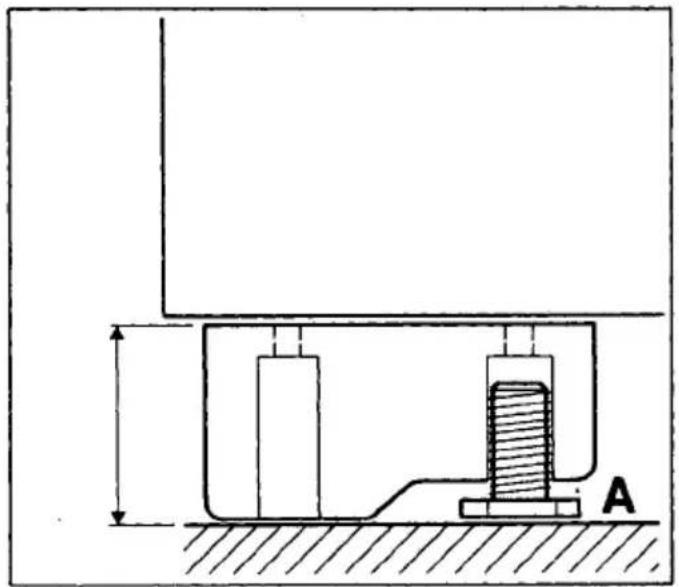
Adjustable feet - working height 85/86 cm
Fig. 1
Your appliance is equipped as standard with 4 adjustable feet which you can twist in or out to correct any floor irregularities. If your refrigerator is installed under a continuous worktop, all 4 adjustable feet must be screwed down to the low-lying position (A).
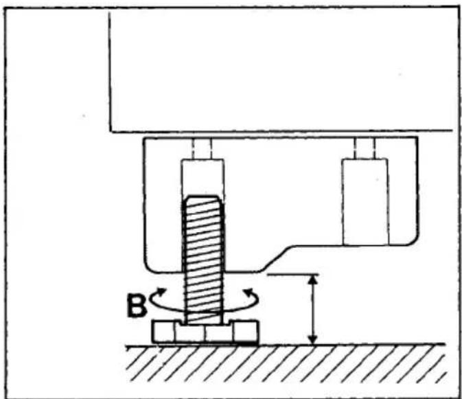
Special accessory: Adjustable feet – working height 90/91 cm
Fig. 2
If your refrigerator is intended for a working height of 90/91 cm, four 6 cm long adjustable feet (B) (E-No. 621 833 004) should be ordered and screwed in.
Rehingeing the door on appliances without plinth
Figs. 3, 4, 5, and 6
Before connecting your appliance to the power supply, you should check whether the door hinge should be changed over from right (as delivered) to left if required by the installation site and operability. Incline the appliance backwards.
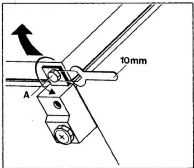
To remove the door, unscrew pivot (A) (Fig. 3). Lift door off door bearing and remove downwards.
Place door aside and protect against damage. Keep pivot (A) in a safe place.
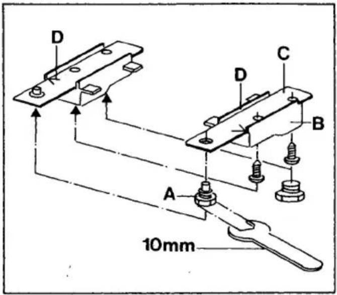
Change front feet (B) and lower door bearing (C) (Fig. 4).
When fitting the door bearing, ensure that the embossing 540 or 595 (as appliance width dimension) is legible and that the marked arrow (D) points outwards to the appliance side.
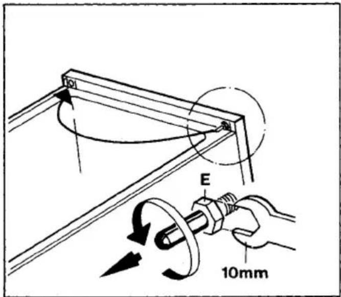
Unscrew pivot (E) and screw in above on LH side (Fig. 5). Mount door in pivot above, close door, and screw in pivot (A) below (Fig. 3).
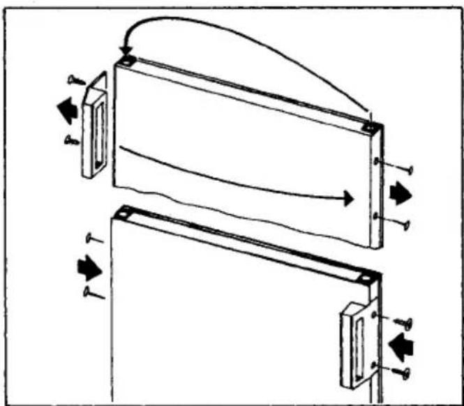
Change over door handle and fix. Plug screwholes with hole seals (Fig. 6).
Rehingeing the door on appliances with plinth
Figs. 5, 6, 7, 8
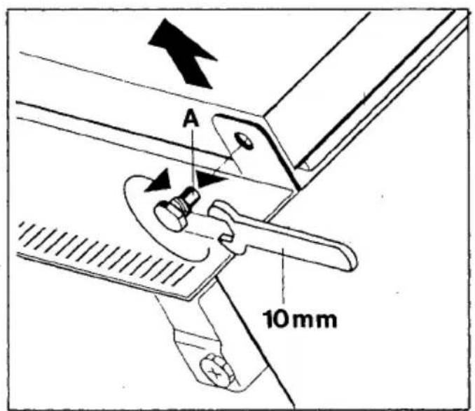
Incline appliance backwards To remove the door, unscrewe pivot (A) (Fig. 7). Lift door off door bearing and remove downwards.
Place door aside and protect against damage. Keep pivot (A) in a safe place.
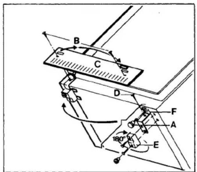
Unscrew screws (B) (Fig. 8). Release and remove plinth screen (C) by inserting a screwdriver into external ventilation slot of housing.
Unscrew screw (D).
Change front feet (E) and lower door bearing (F) as illustrated.
Vertically align door bearing and screw in screw (D) without predrilling.
Insert plinth screen (C) and screw in screws (B). Unscrew pivot (E) and insert above on LH side (Fig. 5).
Mount door in pivot above. Close door and insert pivot (A) below (Fig. 7).
Change over door handle and fix (Fig. 6).
Plug screwholes with hole seals.
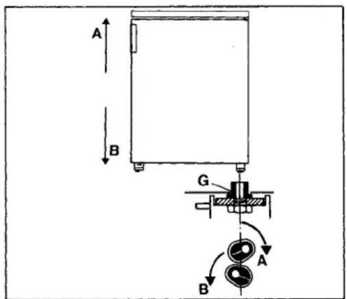
Aligning the appliance door
Fig. 9
Remove door.
Remove lower bearing bushing from door. Twist as necessary to adjust and refit. When fitting bearing bushing (A), raise upper LH door edge. When fitting bearing bushing (B), lower upper LH door edge. If door is mounted at left, proceed in reverse sequence.
Refit door.
Your refrigerator needs air
The refrigerating unit of your refrigerator is designed for maintenance-free operation. What it should never lack is good ventilation. Air is supplied under the door through the ventilation slot. Air is extracted through the upper ventilation grille. Never obstruct these openings by plinth screens or crockery.
Mounting under a continuous worktop
Figs. 10, 11a/b and 12
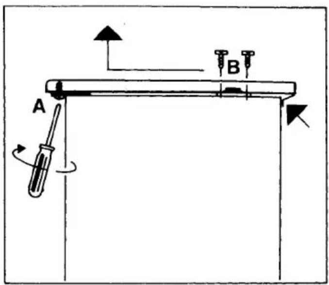
After removal of the storage panel, your appliance can be installed under a continuous worktop (Fig. 10).
For this purpose:
- Open the door.
- Unscrew Phillips screws (A).
- Lift the worktop slightly at the centre near the ventilation grille, slide forwards, and lift upwards.
- Unscrew panel holder (B).
- Seal drillholes with a moisture-resistant adhesive tape to prevent penetration of moisture.
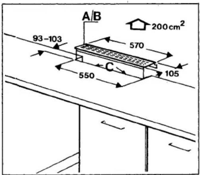
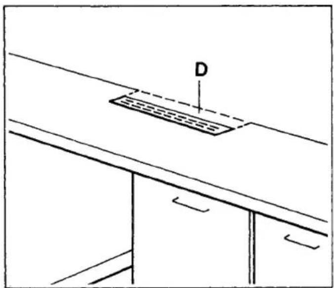
In the worktop at the rear, an air outlet opening of at least 200 cm ^2 and a ventilation grille (A/B) matching the worktop design should be provided (Fig. 11a).
Fig. 11b
Please also use this ventilation grille even if the continuous work-top is already fitted with a ventilation grille with bracket (D); otherwise, under certain circumstances there may be no certainty that air can be expelled in sufficient quantities. To this end, remove the old ventilation grille including the bracket (D) from the work-top and then fasten the new ventilation grille in position.
Varnish the cut surfaces of the worktop (C) to prevent penetration of moisture.
Special accessories:
A = Ventilation grille, brown (E-No. 621 814 002)
B = Ventilation grille, white (E-No. 621 825 004)
(For UK only: ventilation grilles are not stocked by AEG as these are readily available from builders merchants or DIY shops).
The appliance-wall distance must be at least 30 mm and should be checked before the ventilation grille is inserted.
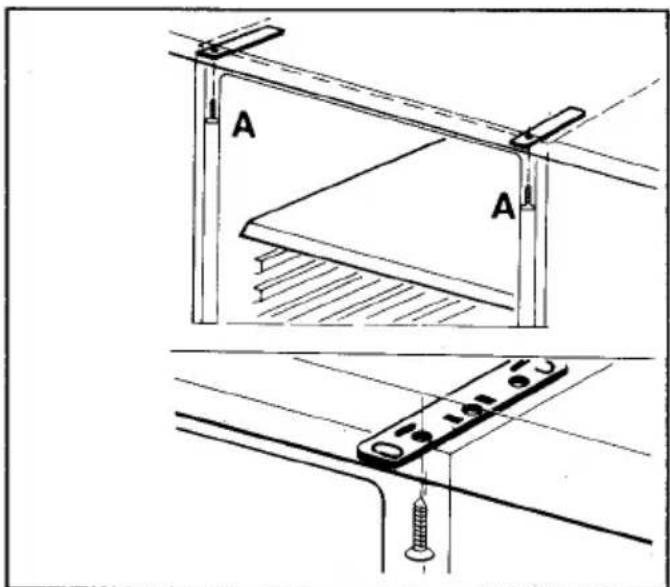
The refrigerator is fastened with 2 mounting screws (A) under the continuous worktop (Fig. 12). The front mounting screws of the removed worktop can be used for this purpose.
Changing the freezer compartment door
Figs. 13–16
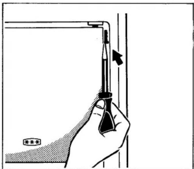
With the door closed, press the pivot upwards with a screwdriver (Fig. 13).
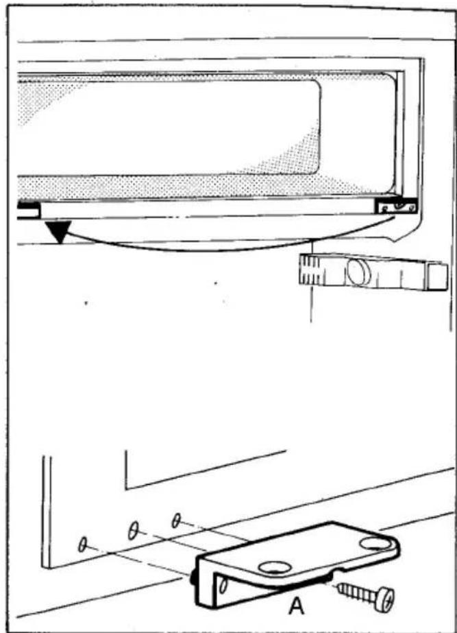
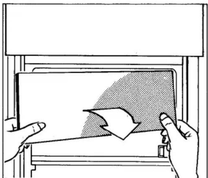
Open the door ajar, lift below, and remove downwards (Fig. 14).
Change over and fix lower bearing (Fig. 15).
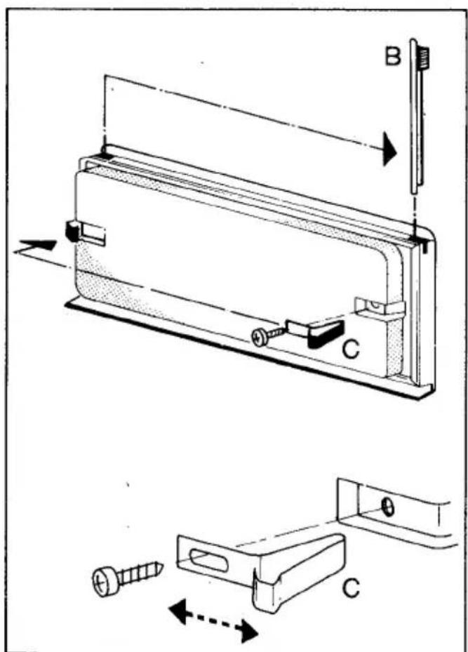
Transfer pivot (B) and clip (C) to opposite side (Fig. 16).
The clip (C) can be readjusted if necessary.
Mount freezer compartment door with pivot above, press down, and press down pivot with screwdriver.
The freezer compartment door can be aligned upwards or downwards by adjustment of the lower bearing (A).
Decorating the appliance door
Figs. 17–21
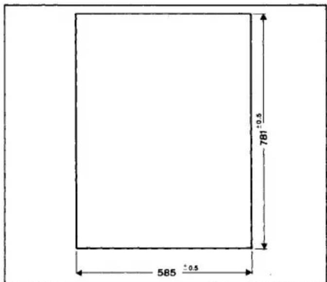
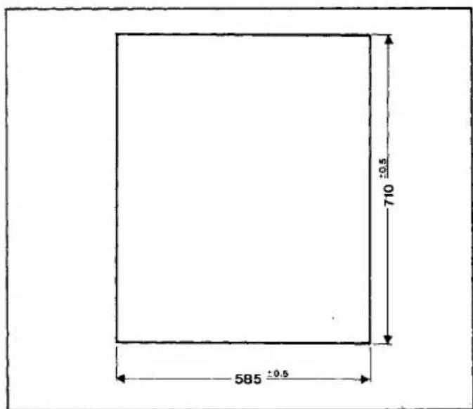
The door front of your appliance can be visually matched to surrounding kitchen units with a decorative trim of up to max. 4 mm thickness using a decor frame retrofitting kit as a special accessory.
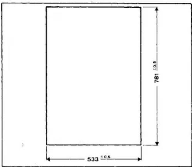
Decorative trim dimensions: (Figs. 17–19).
To establish the dimensions of the decor panel, recheck the dimensions of your appliance door to make doubly sure.
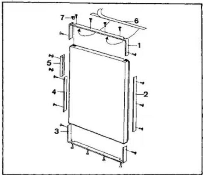
To fit, please proceed as follows (Fig. 20):
- Remove door (see "Rehingeing the door").
- Unscrew handle and hole seals of screwholes.
-
Locate frame strips (1), (2), (3), and (4) as well as handle (5).
-
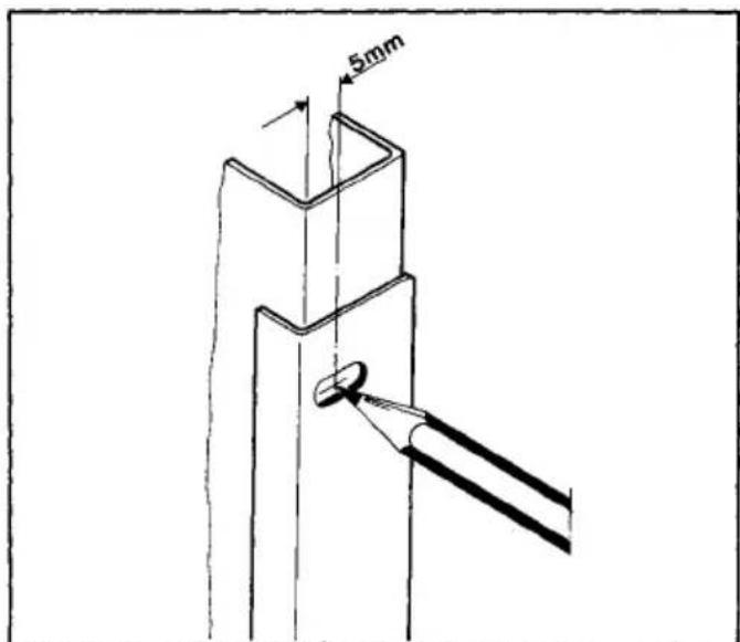
Mark pattern of holes as per sketch (Fig. 21), arranging the pattern of holes in the front part of the slot.
-
Drill pattern of holes with 2.1 mm dia.
-
Loosely arrange lower frame strip (3) and side strips (2) and (4) with screws.
-
Slide in decorative trim from above.
-
Fix handle (5) with 2 screws (not forgetting washers).
-
Stick double-sided adhesive tape (6) below upper frame strip (1).
-
Fix upper frame strip (1) with screws.
-
Press on strips and handle and tighten screws.
-
Insert cover (7).
-
Refit door (see "Rehingeing the door").
If a thin decorative trim is being fitted, it is recommended to use double-sided adhesive tape.
Matching with a variable worktop
Fig. 22
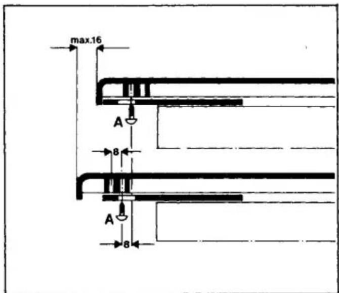
The variable worktop – on some models – enables you to match the front panel of your appliance to those of other domestic appliances or kitchen units with millimetre accuracy. For this purpose, the worktop can be shifted forward in two steps of up to 16 mm.
Proceed simply as follows:
- Open door.
- Loosen two Phillips screws (A) on LH and RH sides.
- Slide worktop forward to required dimension.
- Retighten screws (A).
If the worktop needs to be shifted more than 8 mm, unscrew screws (A) and screw them in the second group of holes after shifting the worktop (lower diagram).
Electrical connection
WARNING - THIS APPLIANCE MUST BE EARTHED
Please ensure that the voltage and current indicated on the rating plate agrees with the voltage of your electricity supply.
220/240 volts \~ (i. e., 220/240 V AC).
If your appliance has been equipped with a mains lead with a moulded-on type plug, you must comply with the following regulations: The plug moulded on to the cord incorporates a fuse. For replacement, use a 13 amp BS 1362 fuse. Only ASTA approved or certified fuses should be used. The fuse cover/ carrier must be replaced in the event of changing the fuse. The plug must not be used if the fuse cover/ carrier is lost. A replacement cover/carrier must be obtained from an electrical goods retailer. If the socket outlets in your home are not suitable for the plug fitted to the appliance, then the plug must be cut off and an appropriate one fitted. When fitting the plug please note the following points:
Important
The wires in the mains lead are coloured in accordance with the following code:
| Green and Yellow | Earth |
| Blue | Neutral |
| Brown | Live |
As the colours of the wires in the mains lead of this appliance may not correspond with the coloured markings identifying the terminals in your plug, proceed as follows:
- The wire which is coloured GREEN and YELLOW must be connected to the EARTH terminal in your plug, which is marked with the letter E or by the earth symbol 12 or coloured GREEN, or GREEN and YELLOW.
- The wire which is coloured BROWN must be connected to the LIVE terminal which is marked with the letter L or coloured RED.
- The wire which is coloured BLUE must be connected to the neutral terminal which is marked with the letter N or coloured BLACK.
When wiring the plug, ensure that all strands of wire are securely retained in each terminal. Do not forget to tighten the mains lead clamp on the plug.
Warning! A cut off plug inserted into a 13 amp socket is a serious shock hazard. Ensure that the cut off plug is disposed of safely.
Voltage 220/240 V AC
Fuse rating 13 amps
See rating plate for further information.
The rating plate is located on the left inside the appliance.
Plug socket
Fig. 23
The plug socket necessary for connection of your appliance to the electricity supply should be positioned so that it is possible to pull out the appliance plug.
If your appliance is installed under a continuous worktop, the plug socket should be provided as shown in Fig. 23.
A concealed protective contact plug socket requires 10 A/16 A fusing.
Cleaning before using for the first time
Like all new appliances, your freezer will smell "new". For this reason, the interior of the freezer and all accessories should be cleaned before use (see also "Defrosting and cleaning".
Automatic refrigerator without star compartment Starting up and temperature regulation
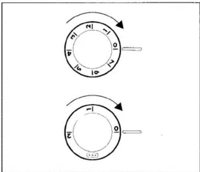
Fig. 24
The knob for temperature selection is located in the refrigerator compartment.
Setting "0" means: Off.
Rotation in direction "1": Lighting on, refrigerating unit on, the latter then operating automatically.
Setting "1" means:
highest refrigerating temperature, warmest setting. Setting "7" means:
lowest refrigerating temperature, coldest setting. The ambient temperature, loading, and frequent door opening affect the internal temperature. When the setting is changed, the refrigerating unit does not start immediately if defrosting is then in progress.
Automatic refrigerator with star compartment Starting up and temperature regulation
Fig. 25
The knob for temperature selection is located in the refrigerator compartment.
Setting "0" means: Off.
Rotation in direction "1": Lighting on, refrigerating unit on, the latter then operating automatically.
Setting "1" means:
highest temperature, warmest setting.
Setting *** (end-stop) means:
lowest temperature, coldest setting.
a) During normal refrigeration without use of the freezer compartment, you are recommended to use setting "1". If you require a lower temperature, use setting "2" or ***.
b) When storing frozen food in the freezer compartment, use setting ***. The temperature is then -18 °C and lower.
The ambient temperature, loading, and frequent door opening affect the internal temperature. When the setting is changed, the refrigerating unit does not start immediately if defrosting is then in progress.
Correct storage
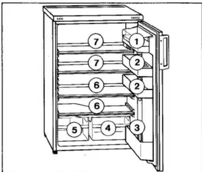
Figs. 26 and 27
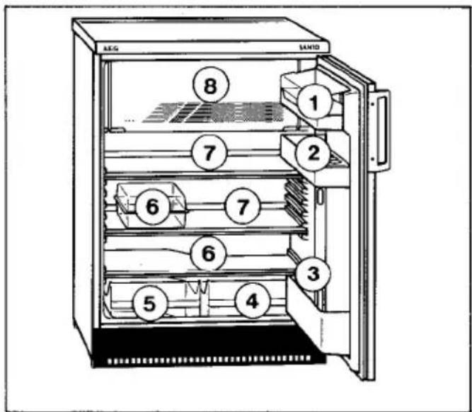
① = Butter and cheese
② = Eggs, tubes, preserves
③ = Drinks
4 = Cheese, fruit
5 = Vegetables
6 = Meat, salami, cooked meats, dairy produce
⑦ = Ready meals, pastries, preserves
⑧ = Frozen food, ice-cream, ice-cubes
Variable inner door
Depending on the height of the food stored, the door racks can be placed in other holders or removed.
Inserting and adjusting the storage racks
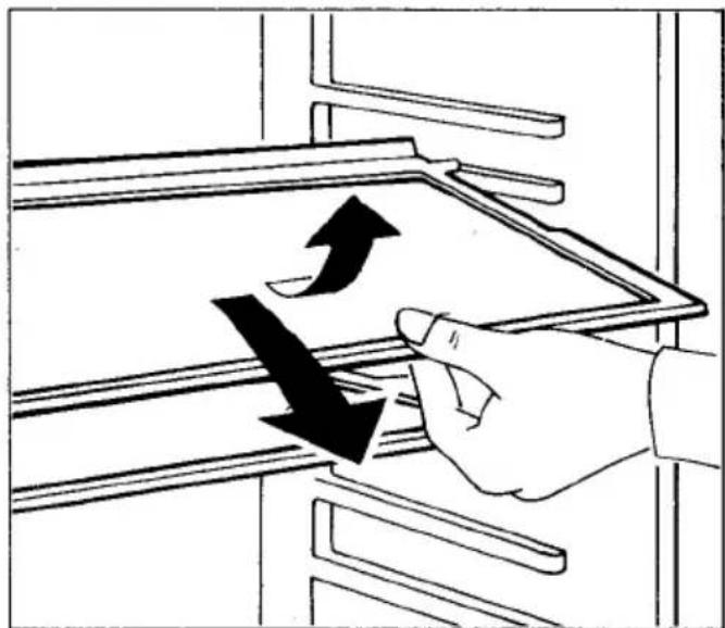
Fig. 28a
One storage rack must be placed in the lowest guides above the fruit and vegetable trays.
If you want to adjust the distance between the storage racks, you should pull the storage rack slightly forwards until it can be swivelled upwards or downwards and removed. To insert at another level, please proceed in the reverse sequence.
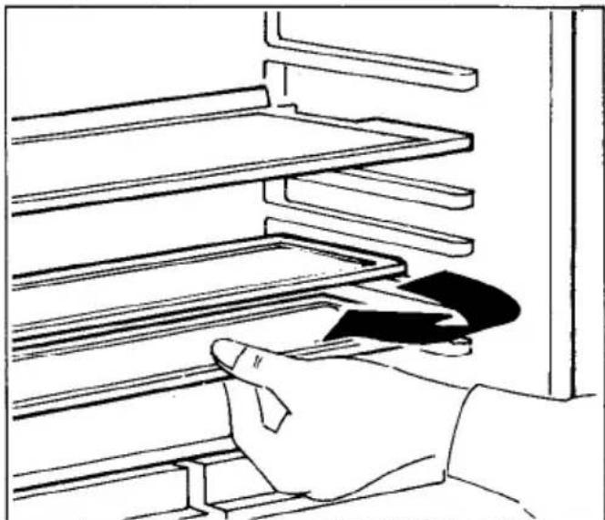
Fig. 28b
If, for instance, you wish to store bottles, cans, or jars in the upright position, please move the front half of the VARIO glass shelf (if fitted) to a different level. You will thus gain the necessary space to store tall items on the shelf below.
VARIO tray set
Depending on model and features, your refrigerator is equipped with different trays allowing versatile combination. The half-trays can be individually or vertically stacked or used as a closed box. Smaller trays can be inserted in larger ones above and thus allow refrigerated food separation depending on type and size.
Ice-tray
In the ice-tray, you can make ice-cubes, ice-cream, sorbet, etc. in the freezer compartment.
If the ice-tray sticks to the freezer compartment floor, never use sharp or pointed objects to loosen it.
Defrosting
Defrosting of the evaporator on the rear wall of the refrigerator compartment occurs automatically. The water evaporates automatically.
The freezer compartment need not be defrosted very frequently. To do this, unplug the appliance (or otherwise disconnect it, e. g. by removing the fuse), and leave the door ajar.
During defrosting, wrap the frozen food in several layers of newspaper and store in a cool place.
Never use any additional heat sources for defrosting. Before defrosting, pull the upper storage area slightly forwards and place a bowl underneath to catch the thaw water.
When the layer of frost has melted, wipe the surfaces well dry.
Cleaning and care
During cleaning, a refrigerator must basically not be connected to the mains supply (pull out the mains plug or remove the fuse).
Make sure that the drain opening of the gutter is always free. If the water drain opening becomes choked, it should be cleaned with the aid of a wire.
GB
Some organic solvents as well as essential oils (e. g. juice from lemon and orange peel, butyric acid) attack the plastic parts.
Do not forget that, even in the refrigerator, food stored too long may spoil. To prevent any odours from forming, the contents should therefore be checked from time to time (including accessories) and thoroughly cleaned with lukewarm water to which a mild, non-abrasive cleaning agent containing no acetic acid can be added. Finally, wash with clean water and wipe dry. After cleaning of the refrigerator compartment, promptly reconnect the appliance to the power supply (see section on Starting up).
When not in use
If your refrigerator is to remain unused for any length of time, it must be disconnected (unplugged) from the electricity supply. The appliance should then be cleaned thoroughly and the appliance doors left ajar to prevent any odours from forming.
Faults and servicing
To maintain the safety of your appliance, you should only have repairs, especially on live parts, performed by a trained electrician. In the event of a fault, please contact your retailer or the service centre direct.
Before calling the service centre, please check that the power supply is in order. Power supply faults will be rectified by your electrician.
In the event of appliance faults, please notify the nearest service centre promptly. To avoid unnecessary journeys and costs, please state the:
- model designation,
- E-number and
- F-number
of your appliance.
These indications are given on the rating plate inside your appliance on the LH side.
Important! Unjustified service centre calls must be paid for even during the guarantee period.
Minor repairs you can carry out yourself
- Interior lighting
If the bulb is defective, you can easily change this yourself. To do this, unplug the appliance (or otherwise disconnect it, e.g. by removing the fuse). The bulb can be reached from the rear of the cover. Use only a 15 W spare bulb.
- Spare parts:
Spare parts can be ordered from the service centre. You can fit them yourself without any special skill or training.
For example
- Butter and cheese compartment
- Door racks and bottle compartment
- Egg holders
- Fruit and vegetable trays
- Storage racks.
Hints on correct use
Store your food, depending on type and sensitivity, in the appropriate temperature zones. This will enable you to achieve an optimum storage duration (see "Correct storage"). Ensure good packaging or covering of the food to be stored in your refrigerator. This ensures that flavour, colour, moisture, and freshness are retained.
Clean the refrigerator space regularly. This ensures that your food is hygienically stored and that unwanted odours are avoided.
Never place hot food in your refrigerator for cooling.
Hints on energy-saving
Do not install your refrigerator next to a radiator or oven. Through high ambient temperature, the temperature regulator switches on the refrigerating unit more frequently and for longer.
Ensure good ventilation of your refrigerator. Never obstruct the ventilation slots.
Do not place any hot food in the freezer – first allow the food to cool to room temperature.
Do not open the doors unnecessarily and close them again as quickly as possible.
AEG Hausgeräte AG
Postfach 1036
D-90327 Nürnberg
© Copyright by AEG
H 271 268 100 - 1093/03 - 150
AEG Domestic Appliances Ltd
Customer Care Department
55-77 High Street
Slough
Berkshire SL1 1DZ
Telephone: 08705 350350