
ST-G90L - Tuner TECHNICS - Kostenlose Bedienungsanleitung
Finden Sie kostenlos die Bedienungsanleitung des Geräts ST-G90L TECHNICS als PDF.


| Produkttyp | Quartz-Synthesizer AM/FM Stereo Tuner |
| Modell | ST-G90L |
| Marke | Technics |
| Abmessungen (B × H × T) | 430 × 93,5 × 288 mm |
| Gewicht | 3,5 kg |
| Stromversorgung | AC 50/60 Hz, 110 V / 127 V / 220 V / 240 V (umschaltbar) |
| Leistungsaufnahme | 9,5 W |
| FM-Frequenzbereich | 87,50 – 108,00 MHz |
| MW-Frequenzbereich | 522 – 1611 kHz (9-kHz-Schritte) / 530 – 1620 kHz (10-kHz-Schritte) |
| LW-Frequenzbereich | 155 – 353 kHz (9-kHz-Schritte) (nur ST-G90L) |
| FM-Empfindlichkeit (IHF) | 1,5 μV |
| Signal-Rausch-Abstand FM (Mono) | 80 dB |
| Signal-Rausch-Abstand FM (Stereo) | 74 dB |
| Klirrfaktor FM (Mono) | 0,015 % |
| Klirrfaktor FM (Stereo) | 0,02 % |
| Stereo-Trennung (1 kHz) | 60 dB |
| Anzahl Senderspeicher | 39 (FM/AM zufällig) |
| Besondere Funktionen | Automatische RF/IF-Bandwahl, Scan-Level-Einstellung, Aufnahmepegel-Prüfung, Backup-Speicher, Quartz-Lock |
| Lieferumfang | Netzkabel, AM-Rahmenantenne, Stereoverbindungskabel, FM-Innenantenne |
| Reinigung | Weiches, trockenes Tuch; bei starker Verschmutzung mildes Reinigungsmittel |
| Sicherheitshinweise | Netzstecker bei Feuchtigkeit oder Nichtgebrauch ziehen; keine Spray-Insektizide verwenden |
| Zubehör (separat erhältlich) | FM-Außenantenne, Timer (über Steuereingang) |
Häufig gestellte Fragen - ST-G90L TECHNICS
Benutzerfragen zu ST-G90L TECHNICS
0 Frage zu diesem Gerät. Beantworten Sie die, die Sie kennen, oder stellen Sie Ihre eigene.
Eine neue Frage zu diesem Gerät stellen
Laden Sie die Anleitung für Ihr Tuner kostenlos im PDF-Format! Finden Sie Ihr Handbuch ST-G90L - TECHNICS und nehmen Sie Ihr elektronisches Gerät wieder in die Hand. Auf dieser Seite sind alle Dokumente veröffentlicht, die für die Verwendung Ihres Geräts notwendig sind. ST-G90L von der Marke TECHNICS.
BEDIENUNGSANLEITUNG ST-G90L TECHNICS
Technics
QUARTZ Synthesizer AM/FM Stereo Tuner
ST-G90
QUARTZ Synthesizer LW/MW/FM Stereo Tuner
ST-G90L
OPERATING INSTRUCTIONS

Notes:
- Specifications differ according to the area code.
- The "EK" area code, for example, indicates United Kingdom specifications.
- The "EK" indication is shown on the packing case and serial number tag.
Before operating this unit, please read these instructions completely.
Dear Stereo Fan
We want to thank you for selecting this product and to welcome you to the growing family of satisfied Technics product owners around the world. We feel certain you will get maximum enjoyment
from this new addition to your home. Please read these operating instructions carefully, and be sure to keep them handy for convenient reference.
These Operating Instructions are applicable to models ST-G90 and ST-G90L. The functions which differ for the two models are indicated in the Operating Instructions.
Contents
• For United Kingdom 2
• Technical Specifications 2
- Suggestions for Safety 3
- Before Use 3
- Accessories 4
- Connections 4
- Antenna Connections.... 5
- Front Panel Controls and Functions ..... 6
• Memory Presettings.... 8 - Listening to Radio Broadcasts....10
• FM automatic RF/automatic IF .....11 - Recording FM broadcasts....11
- Troubleshooting Guide....12
- Maintenance 12
For United Kingdom
("EK" area code model only)
The "EK" indication is shown on the name plate.
Important
THE WIRES IN THIS MAINS LEAD ARE COLOURED IN
ACCORDANCE WITH THE FOLLOWING CODE.
BLUE NEUTRAL
BROWN. LIVE
As the colours of the wires in the mains lead of this unit may not correspond with the coloured markings, identifying the terminals in your plug, proceed as follows. The wire which is coloured BLUE must be connected to the terminal which is marked with the letter N or coloured BLACK.
The wire which is coloured BROWN must be connected to the
cromunal which is marked with the letter L or coloured RED
Technical Specifications (DIN 45 500)
FM TUNER SECTION
| 19 kHz | -75 dB (-80 dB, IHF) | MW (at 999 kHz) | 40 dB | |
| Frequency range | 87.50~108.00 MHz | 38 kHz | -75 dB (-80 dB, IHF) | 40 dB |
| 87 525~108.00 MHz (+25 kHz shift) | Channel balance (250 Hz~6,300 Hz) | ±1.0 dB | IF rejection | |
| Sensitivity | 1.5 μV (IHF, usable) | Limiting point | 0.85 μV | MW (at 999 kHz) |
| S/N 30 dB | 1.3 μV (75Ω) | Bandwidth | LW (at 254 KHz) | |
| S/N 26 dB | 1.2 μV (75Ω) | IF amplifier | 180 kHz | |
| S/N 20 dB | 0.9 μV (75Ω) | FM demodulator | 1000 kHz | |
| IHF 46 dB stereo quieting sensitivity | 28 μV/75Ω | Antenna terminals | 75Ω (unbalanced) | GENERAL |
| Total harmonic distortion | Output voltage 0.3V (0.6V IHF) | |||
| MONO (normal) | 0.015% | AM TUNER SECTION | Power consumption 9.5W | |
| STEREO (normal) | 0.02% | Power supply | ||
| S/N | Frequency range | For United Kingdom and Australia | ||
| MONO | 80 dB (86 dB, IHF) | MW | AC 50 Hz-60 Hz, 240V | |
| STEREO | 74 dB (79 dB, IHF) | (For Europe and Australia) | For continental Europe AC 50 Hz-60 Hz, 220V | |
| Frequency response | 522 kHz~1611 kHz (9 kHz-steps) | For others | ||
| 4 Hz~15 kHz, +0.5 dB~-0.5 dB | 530 kHz~1620 kHz (10 kHz-steps) | AC 50 Hz/60 Hz, 110V/127V/220V/240V | ||
| Alternate channel selectivity | (For Saudi Arabia and others) | Dimensions (W×H×D) 430 × 93.5 × 288 mm | ||
| normal ±400 kHz | 55 dB | 531 kHz~1602 kHz(9 kHz-steps) | (16-30/32" × 2-22/32" × 9-11/32") | |
| super narrow +200 kHz | 30 dB | 530 kHz~1600 kHz (10 kHz-steps) | Weight 3.5 kg (7.7 lb ) | |
| Capture ratio | 1.0 dB | LW 155 kHz~353 kHz (9 kHz-steps) | ||
| Image rejection at 98 MHz | 130 dB | 153 kHz~351 kHz (-2 kHz shift) | ||
| IF rejection at 98 MHz | 130 dB | Sensitivity (S/N 20 dB) | Notes: | |
| Spurious response rejection at 98 MHz | 130 dB | MW | 20 μV, 300 μV/m | 1 Total harmonic distortion is measured by the digital spectrum analyzer (H.P. 3045 system). |
| AM suppression | 55 dB | LW | 50 μV | |
| Stereo separation | Selectivity (-9 kHz) | 2. Specifications are subject to change without notice Weight and dimensions are approximate | ||
| 1 kHz | 60 dB | MW (at 999 kHz) | 50 dB | |
| 10 kHz | 45 dB | LW (at 254 kHz) | 50 dB | |
THIS TUNER/RECEIVER IS CAPABLE OF RECEIVING THE NEW AM STEREO BROADCASTS FROM THE AM BAND RADIO STATIONS. HOWEVER LIKE MANY TUNERS AND RECEIVERS CURRENTLY AVAILABLE ON THE MARKET IT WILL REPRODUCE THIS AM STEREO SIGNAL ONLY IN AM MONO. WHICH, IN EFFECT, IS OF NO LESSER QUALITY THAN YOUR EXISTING AM MONO TUNER/RECEIVER.
Suggestions for Safety
■ Use a standard electrical AC wall outlet
- Use from an AC power source of high voltage, such as for air conditioners, is very dangerous.
Be extremely careful not to make a connection to the electrical outlet for a large air conditioner or central-heating unit which uses high voltage, because there is the possibility of fire.
- A DC power source cannot be used.
Be sure to check the power source carefully, especially on a ship or other place where DC is used.
■ Connection and removal of the power cord plug
- Wet hands are dangerous.
A dangerous electric shock may result if the plug is touched by wet hands.
- Don't pull the power cord.
Always grasp the plug; never pull the cord itself.
■ Never attempt to repair or reconstruct this unit
A serious electric shock might occur if this unit is repaired, disassembled or reconstructed by unauthorized persons, or if the internal parts are accidentally touched.
For families with children
Never permit children to put anything, especially metal, inside this unit. A serious electric shock or malfunction could occur if articles such as coins, needles, screwdrivers, etc. are inserted through the ventilation holes, etc. of this unit.
■ Turn off after use
If the unit is left for a long time with the power on, this will not only shorten its useful operation life, but may also cause other unexpected trouble.
Before Use
Be sure to disconnect the mains cord before adjusting the voltage selector.
Use a minus (−) screwdriver to set the voltage selector (on the rear panel) to the voltage setting for the area in which the unit will be used.
■ If water is spilled on the unit
Be extremely careful if water is spilled on the unit, because a fire or serious electric shock might occur. Immediately disconnect the power cord plug, and consult with your dealer.
■ Place the unit where it will be well ventilated, and away from direct sunlight
Place this unit at least 10 cm (4") away from wall surfaces, etc., and away from direct sunlight.
- Keep the unit away from heaters, etc.
Heat can damage the external surfaces as well as internal circuits and components.
■ Avoid spray-type insecticides
Insecticides might cause cracks or "cloudiness" in the cabinet and plastic parts of this unit. The gas used in such sprays might, moreover, be ignited suddenly.
■ Never use alcohol or paint thinner
These and similar chemicals should never be used, because they may damage the finish.
■ If trouble occurs
If, during operation, the sound is interrupted or indicators no longer illuminate, or if abnormal odor or smoke is detected, immediately disconnect the power cord plug, and contact your dealer or an Authorized Service Center.
(If the power supply in your area is 117 V or 120 V, set to the "127 V" position.)
Note that this unit will be seriously damaged if this setting is not made correctly. (There is no voltage selector for some countries; the correct voltage is already set.)
Accessories
(Refer to pages 4 - 5.)
- AC power supply cord.... 1 - AM loop antenna .... 1
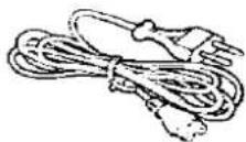
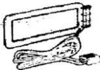
- Stereo connection cable .... 1 - Attachment plug .... 1
(For United Kingdom only)


M Indoor antenna.
• AM antenna holders

natural_image
Simple line drawing of a bundle of rope or wires on a wooden surface (no text or symbols)

Note: Configuration of AC power supply cord and FM indoor antenna differs according to area.
Connections
Control input terminal (CONTROL INPUT):
This terminal is used for the connection of a timer for the purpose of controlling the tuner by means of an external control signal.
This unit
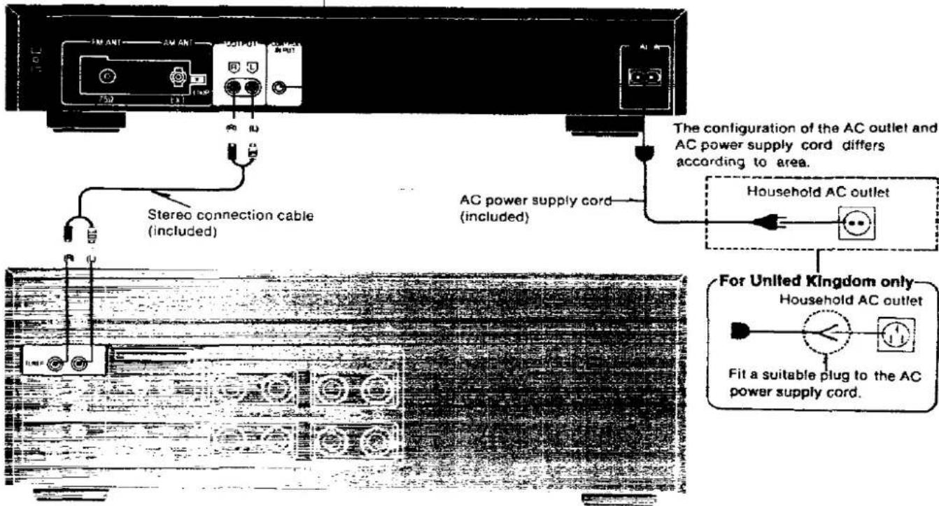
Amplifier (option)
Antenna Connections
The indication AM used here includes both MW and LW for model ST-G90L.
Note: An outdoor antenna should be installed by a competent technician only.
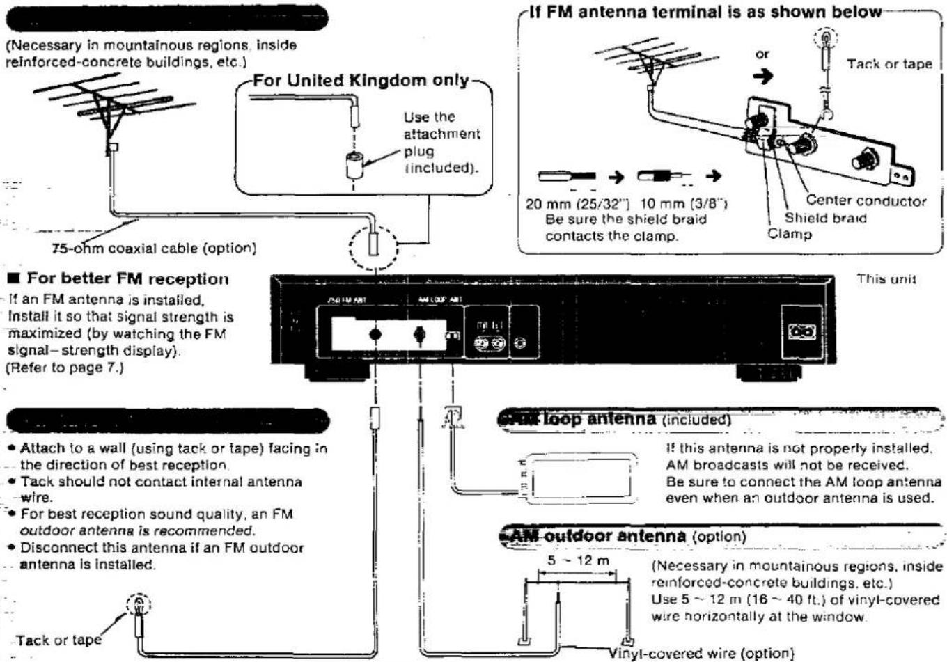
(Necessary in mountainous regions, inside reinforced-concrete buildings, etc.)
■ For better FM reception
If an FM antenna is installed, Install it so that signal strength is maximized (by watching the FM signal-strength display). (Refer to page 7.)
This unit
- Attach to a wall (using tack or tape) facing in the direction of best reception.
- Tack should not contact internal antenna-wire.
- For best reception sound quality, an FM outdoor antenna is recommended.
- Disconnect this antenna if an FM outdoor antenna is installed.
If this antenna is not properly installed, AM broadcasts will not be received. Be sure to connect the AM loop antenna even when an outdoor antenna is used.
(Necessary in mountainous regions, inside reinforced-concrete buildings, etc.) Use 5 \~ 12 m (16 \~ 40 ft.) of vinyl-covered wire horizontally at the window.
- Connect the AM loop antenna to the AM antenna terminals located on the rear panel of the unit.
Installation of the AM loop antenna
- Pay attention to the following points when attaching the antenna.
- Do not attach it horizontally (to do so would impair reception).
- Do not attach it close to metal surfaces (to do so would result in noise).
- Do not attach it close to power cords, speaker wires, etc. (to do so would result in noise).
- Do not attach it close to a tape deck (when the tape deck is being used, chirping or beeping sounds may be received).
-When attaching the antenna to a wall, column or rack
Find the height and direction of the antenna where reception is best and then fix it vertically to the wall, rack, etc.

When attaching the antenna to the unit
This type of installation may cause impaired reception or result in signal noise. If possible, attach the antenna to the rack, a wall, or a column.
Move the antenna toward the right or left to find the point of best reception.

Front Panel Controls and Functions
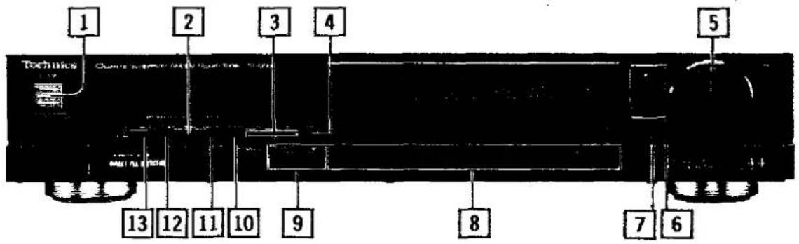
Control section
Power "standby ♦/on" switch (power "standby ♦/on")
This switch switches ON and OFF the secondary circuit power only. The unit is in the "standby" condition when this switch is set to the "standby 6" position. Regardless of the switch setting, the primary circuit is always "live" as long as the power cord is connected to an electrical outlet.
2 FM IF band selector (IF band)
The built-in computer of this unit detects the signal condition and functions accordingly to select the FM IF band automatically. This button is used to change it manually.
3 Memory-search button (memory search)
This button is used to confirm a memory presetting. If the button is pressed, the memorized frequency and "channel" number will be shown one after the other in order.
4 Memory button (memory)
This button is used when preset memory setting of the preset-tuning buttons is made.
5 Tuning control (tuning)
This control is used to select an FM or AM broadcast. When turning the control to the left, the frequency change downward. When turning the control to the right, the frequency change upward.
6 Tuning-mode selector/Indicator (tuning mode)
Each time this selector is pressed, the selection changes, in sequence, to "auto", "manual" and "lock".
auto:
At this position, broadcast stations are automatically found when the tuning control is turned to the left or right until the frequency changes.
manual:
At this position, the tuning control can be used to locate the desired station.
lock:
At this position, the broadcast station now being heard is locked in. and other broadcast stations cannot be tuned to, even if turning the tuning control.
7 Scan level selector (scan level)
This button is used for setting or confirming the level of the reception signal during automatic FM tuning. (Refer to page 8.)
8 Preset-tuning buttons (39 channel random preset tuning)
These buttons are used to preset FM and AM broadcast frequencies into the memory of this unit, and are also pressed to select the desired preset frequencies.
Note:
Refer to pages 8\~9 for information concerning preset memory.
9 Band selectors (band selector)
FM:
Press this button to listen to an FM broadcast. Ireq shift:
When the button is pressed slightly longer, the reception frequency increases by 0.025 MHz (25 kHz).
(The final figure of the frequency display changes to "2" or "7".)
In order to return to the original frequency indication, press this button for about 2 seconds again.
AM: (For ST-G90L; MW)
Press this button to listen to an AM broadcast. allocation:
This button is also used to select a frequency step of either 9 kHz or 10 kHz.
When the AM button is pressed for about 4 seconds, the AM frequency step will change to 10 kHz per step.
(This step is set to 9 kHz before shipment.)
Set to the appropriate position for your locality. LW: (ST-G90L only)
Press this button to listen to an LW broadcast. freq shift:
When the LW button is pressed for about 4 seconds during reception of an LW broadcast, the LW frequency will decrease by 2 kHz.
So, for example, to receive 153 kHz, tune to 155 kHz, and then press this button
In order to return to the original frequency indication, press this button for about 4 seconds again
10 Recording-level check button (rec level)
This button is to be used for adjustment of the recording level when recording an FM broadcast. (Refer to page 11.) Other operations cannot be performed while the recording-level-check indicator is illuminated.
To perform other operations, first be sure that the recording-level-check indicator is OFF.

FM mode selector (FM mode)
If noise is excessive in stereo broadcasts, a switchover to monaural reception can be made.
When there is a change to monaural reception, the illumination of the FM mode indicator changes to the "mono" position.
12 FM RF-band selector (RF band)
This button can be used to switch the RF bandwidth to either the "normal" width or the "super narrow" width by manual operation.
Interference signals are removed if switched to "super narrow".
13 FM RF-band automatic-selector (auto RF)
It sometimes happens, during the reception of FM broadcasts, that a station other than the desired station is received, or interference noise is excessive, even though there is no broadcast station other than the desired station on a nearby frequency.
The reason for this is that interference signals are produced in a frequency band in which there is actually no broadcast station when two or more strong broadcast stations' signals (interference signals) are input to the unit's "front end" (input stage). These interference signals are known as "cross modulation" interference signals, and they cause interference noise to be heard in the signals from the desired broadcast station.
This model is designed to eliminate such cross modulation interference signals by automatically switching the bandwidth of the RF (radio frequency; high frequency) band to the "super narrow" bandwidth.
-set freq only:
By lightly tapping this selector, the presence or not of interference signals within the broadcast signals being received is detected, and there is an automatic switchover to either the "normal" or "super narrow" circuitry as appropriate.
-all preset ch:
If this selector is pressed and held for a slightly longer time, the presence or not of interference signals within the broadcast signals of all FM broadcast stations that have been preset to the unit's memory is detected. There is then an automatic switchover to either the "normal" or "super narrow" circuitry as appropriate, and then an entry is automatically made (to the memory for these same "channels") of the "normal" or "super narrow" reception condition.
Display section
A Quartz-lock indicator (quartz lock)
This indicator illuminates when tuned precisely to an FM or AM station.
B FM RF/IF band indicator (RF/IF band)
These indicators show the FM reception conditions. (Refer to pages 10\~11.)
C FM RF/IF automatic-select indicator (RF IF auto)
This indicator illuminates when the FM RF-band automatic-selector is pressed.
D FM signal-strength display (FM signal)
This display usually shows the reception level of FM broadcasts (maximum 86 dB): when the scan-level selector is pressed and held, the station-tuning level is displayed in the sequence 30 - 40 - 50.
E Recording-level-check indicator (rec)
F FM stereo indicator (stereo)
This indicator automatically illuminates when an FM stereo broadcast is being received. It will not illuminate if the FM mode selector is set to the moraural mode.
G Memory indicator (memo)
This indicator illuminates when the memory button is pressed.
H FM mode indicator (FM mode)
When FM broadcasts are being received, usually the "auto" indication is illuminated. When the FM mode selector is used to select monaural reception, the illumination of the FM mode indicator changes to the "mono" position.
☐ Channel display (preset ch)
The channel number selected by the preset-tuning buttons is displayed.
Digital frequency display
The reception frequency of the FM or AM broadcast selected by using the tuning control or the preset-tuning buttons is indicated.
K Band indicator (band)
Memory Presettings
The indication AM used here includes both MW and LW for model ST-G90L.
With this unit you may preset as many as 39 radio broadcast stations: FM/AM random presetting. After broadcast stations have been preset as described below, any desired station can be quickly and easily selected.
Automatic memory presetting
ST-G90
The FM broadcasts station and AM station will be automatically preset to "channels" 1 through 39 for FM and 21 through 39 for AM, respectively.
ST-G90L
The FM broadcasts station, MW station, and LW broadcasts will be automatically preset in "channels" 1 through 39 for FM, 21 through 39 for MW, and 31 through 39 for LW, respectively.
Notes: When AM (MW) is automatically preset, the FM stations on "channels" 21 through 39 will be replaced by the new AM (MW) stations. When LW is automatically preset, the AM (MW) stations on "channels" 31 through 39 will be replaced by the new LW stations.

'on" ( 1 - = )
Select the desired band by using the band selecor.
Before presetting the broadcasting stations, press to select the appropriate frequency step for your locality. (Refer to page 6.)

4 Press and then release when the frequency indication begins to change.
The frequency will change upward, and the automatic presetting will begin with the next broadcasting station. It will continue to preset consecutive broadcast stations.
5
For FM reception only
Press and hold the "auto RF"; release when the frequency changes.
(The FM RF IF automatic-select indicator illuminates, and the memory indicator flashes continuously.)
Interference signals for all FM broadcast stations entered in the memory will be detected, removed, and data will be entered in the memory.
The reception condition is displayed in the FM RF/IF band indicator. (Refer to page 10.)
To discontinue interference signals search, press "auto RF".
After the search for interference signals of the broadcasting station now being received finishes, it stops, and the display returns to the display of the frequency.
6
Confirm the names (call signs, etc.) of the broadcasting stations which are preset to each channel, and enter them on the station memory file sheet (page 10).
To set the tuning level (received signals)
When the tuning level of FM signal reception is set, only broadcast stations with signals of that level or higher are entered in the memory. Do this before step 4.
① Press and hold the "scan level"
(The level will then be displayed in the FM signal-strength display. in the 30, 40, 50 sequence)
⑦ Release when the desired level is reached.
(There will then, about two seconds later, be a return to the display of the signal strength of the signals of the broadcast station now being received.)
Notes:
- For automatic presetting in areas where there are less than 39 FM stations, the remaining channels (through channel 39) will be left empty. The empty channels can be filled by using manual memory presetting.
- If a new broadcasting station is preset into a channel, the broadcasting station which was previously entered in that channel will be automatically erased.
- For AM broadcasts with extremely strong signal transmissions, the frequency memorized may be slightly different from the correct frequency. If this occurs, use the manual memory presetting.
Manual memory presetting
Stations can be freely preset to any desired channel.
1
$$ \text { "on" } (\mathbf {1} \rightarrow \mathbf {2}) $$
2 Select the desired band by using the band selecor.
Before presetting the broadcasting stations, press to select the appropriate frequency step for your locality. (Refer to page 6.)
3 Tune to the desired broadcast station by using the "tuning mode" and "tuning".
• Automatic tuning
① Select the "auto" mode by using the "tuning mode".
② The frequency changes as the "tuning" is turned; the tuning will stop when a broadcast station is located.
Repeat this action until the desired broadcast station is located.
Note: When searching for a broadcast station by using the "auto" mode, the search continues until a broadcast station is located. To stop, use the "tuning mode" to select the "manual" mode.
- Manual tuning
① Select the "manual" mode by using the "tuning mode".
② Turn the "tuning" to locate the desired broadcast station.
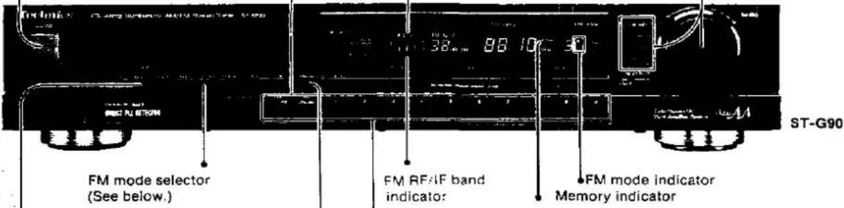
4
[Unreadable]
Lightly tap the "auto RF".
Any interference signals in the FM broadcast signals now being received will be detected and eliminated. (The FM RF IF automatic-select indicator will illuminate.) The reception condition is displayed in the FM RF/IF band Indicator. (Refer to page 10.)
6
Select the desired "channel".
(The selected channel number will be displayed on the channel display.)
• To preset channels 1 through 9: Press button (1-9).
• To presel channels 10 through 19: Press button 1 and the second digit (0 - 9).
- To preset channels 20 through 29: Press button 2 and the second digit (0 - 9).
• To preset channels 30 through 39: Press button 3 and the second digit (0 - 9).
Note:
Make the entry without interruption between steps. If there is an interval of about two seconds or more between steps, you may not obtain the desired settings. In this case, perform steps 5—6 again to reset the memory as necessary.
5
Press. (The memory indicator will
illuminated.)
Note:
If the button is pressed continuously, the frequency will begin to change, and the memory will be preset automatically.
To stop the automatic memory presetting, press this button once again.
7 Enter the name (call sign, etc.) of the preset broadcasting station on the station memory file sheet (page 10).
This completes the procedures for presetting radio broadcast frequencies. The other preset-tuning buttons can be preset in the same way by following steps 2 through 7.
FM mode (FM auto, mono) memory
With this unit, it is possible to enter into the memory FM broadcast stations in the monaural mode. This is convenient when entering into the memory an FM broadcast station that is broadcasting FM stereo signals in which there is much noise.
① Follow above steps 1 through 4.
② Press the "FM mode" to select the "mono" (The "mono" of FM mode indicator will illuminate.)
① Follow above steps 5 through 7.
Listening to Radio Broadcasts
Have you completed the "Memory Presettings" (page 8)?
1 Switch the amplifier ON, and set it for listening to radio broadcasts.
3 Press the desired channel (1 - 39). To select channels 1 through 9:
- To select channels 10 through 19: Press button 1 and the second digit (0 - 9).
• To select channels 20 through 29: Press button 2 and the second digit (0 - 9).
• To select channels 30 through 39: Press button 3 and the second digit (0 - 9).
For station selection using the "tuning": Follow steps 2, 3 of "Memory Presettings" on page 9.
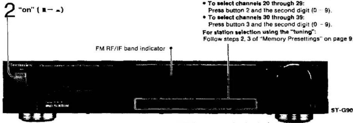
Concerning reception condition of FM broadcasts. (Refer to page 11.)
The reception condition of FM broadcasts is displayed as described below.
| RF section | Desired station | IF section | Desired station |
 |  | ||
| Other broadcast station signals (interference signals) | Other broadcast station signals (interference signals) | ||
RF normal
The, part of the indicator will illuminate if there is no cross modulation interference.
RF super narrow
The · part of the indicator will illuminate (at one side or both sides) if cross modulation interference or noise is mixed with the broadcast signals.
IF normal
The 1 part of the indicator will illuminate if the signals of the desired broadcast station are strong and there are no interference signals.
IF super narrow?
The , part of the indicator will illuminate (at one side or both sides) if interference is mixed with the broadcast signals. If the signals of the desired broadcast station are weak, there will be no illumination of indicate interference.
Station Memory File Sheet
| CH.1 | CH.2 | CH.3 | CH.4 | CH.5 | CH.6 | CH.7 | CH.8 | CH.9 | CH.10 | CH.11 | CH.12 | CH.13 |
| CH.14 | CH.15 | CH.16 | CH.17 | CH.18 | CH.19 | CH.20 | CH.21 | CH.22 | CH.23 | CH.24 | CH.25 | CH.26 |
| CH.27 | CH.28 | CH.29 | CH.30 | CH.31 | CH.32 | CH.33 | CH.34 | CH.35 | CH.36 | CH.37 | CH.38 | CH.39 |
■ "Most-recent" memory
The most-recent memory is a system by which the unit "remembers" the FM or AM broadcast station last heard when this unit is switched OFF, and automatically tunes to that station the next time the power is switched ON.
■ "Back-up" memory
This is the function which preserves the preset memory and most-recent memory functions. In the event of a power failure, or if the power cord of the tuner is disconnected from the electric outlet, the back-up memory will preserve the preset memory and most-recent memory functions for as long as approximately one week.
■ If the memory setting is erased
The memory settings will be erased in the following cases.
For example:
1) If the power cord is disconnected from the electric outlet.
2) If an audio timer is used and the timer does not operate the tuner for a week or longer.
3) If a power failure occurs, etc.
If any of the above occurs, the memory will have to be reset. If the power supply is interrupted for a week or longer, set the power switch of the tuner to the "on" position for an hour or more. Then reprogram the memory.
FM automatic RF/automatic IF
In order to improve tone quality during reception of FM broadcasts when the FM band is crowded with many FM broadcast stations, this model includes "normal" circuitry and "super narrow" circuitry both for the RF (radio frequency) stage and for the IF (intermediate frequency) stage. This special circuitry functions to detect interference signals when several conflicting signals are being received, and to automatically select the optimum reception conditions. (There is an automatic switchover to the "super narrow" circuitry when interference signals are present, and to the "normal" circuitry when they are not a problem.)
The "super narrow" circuitry of the RF stage eliminates interference signals caused as the result of two or more strong broadcast station signals. The "super narrow" circuitry of the IF stage eliminates interference signals caused by broadcast station signals on adjacent frequencies.


Recording FM broadcasts
This model is provided with a recording-level check button that is convenient for determining the optimum recording level before beginning the recording. The standard reference signals are rectangular waves, and the setting of the signal level is to an output level of 50% modulation.
Note:
Do not press the "rec level" while a recording is being made, because to do so will interrupt the recording.

1 Press the "rec level".
(The recording-level-check indicator will illuminate, and the check signal will be emitted.)
2 Adjust the recording level by using the recording level control of the tape deck.
- For VU meters and level meters Adjust so that the indication needle is about +2 VU or +2 dB.

• For peak-level meters
Adjust so that the indication is about -2 dB
[Non-Text]
20 100 4 3 2 0 2 1 4 5 -08
- 2018年1月1日
3 Press the "rec level".
(The illumination of the recording-level-check indicator will stop.)
Troubleshooting Guide
Before requesting service for this unit, check the chart below for a possible cause of the problem you are experiencing. Some simple checks or a minor adjustment on your part may eliminate the problem and restore proper operation. If you are in doubt about some of the check points, or if the remedies indicated in the chart do not solve the problem, refer to the directory of Authorized service centers (enclosed with this unit) to locate a convenient service center, or consult your Technics dealer for instructions.
| Problem | Probable cause(s) | Suggested remedy |
| While listening to FM broadcasts | ||
| In an external hissing noise is heard when listening to the broadcast in stereo, but not heard when listening nonaturally. | Due to the differences between a monaural and a stereo signal, a higher level of signal strength is required for proper stereo reception. If the signal level is low, a hissing noise may be produced on the stereo channel. | Try reducing the treble sound by using the treble control of the amplifier.Set the FM mode selector to the monaural position. (Note that the broadcast will then be heard as monaural sound.)Try changing the location, height and/or direction of the antenna.If an indoor antenna is being used, change to an outdoor antenna.Try using an antenna with more elements. |
| Noise is excessive in both stereo and monaural broadcasts. | Poor location and/or direction of the antenna.Transmitting station is too far away. | |
| If the PM stereo indicator or the quartic book indicator signals, without completely normal rating. | Poor location and/or direction of the antenna.Transmitting station is too far away. | Try changing the location, height and/or direction of the antenna.If an indoor antenna is being used, change to an outdoor antenna.Try using an antenna with more elements. |
| Number distortion in the band of stereo broadcasts. | Nearby building or mountain.[Multipath distortion is being caused by the mutual interference of broadcast signals received directly from the transmitting station (direct waves) and signals being reflected from nearby buildings or mountains (reflected waves).] | |
| While listening to AM broadcasts | ||
| In unusual "beat" sound is heard. | Unit is being used at the same time as the television set. | Turn off television set, or use this unit farther away from it. |
| A low-pitched "hum" sound is heard when the broadcast is tuned. | The AM loop antenna connection wires are too close to the power cord. | Place the antenna connection wires and the power cord farther apart. |
| The power supply frequency from the power cord is modulated and heard from the speakers. | Install a special outdoor antenna. | |
| A strange missing noise is produced continuously or intermittently. | Caused by the "discharge phenomenon" and the "oscillation phenomenon" of electric appliances (such as fluorescent lights, TV, small series-type motors, rectification equipment, etc.). | Try placing this unit farther away from such equipment.Install noise-prevention equipment on this unit or on the electric appliance. |
Maintenance
To clean this unit, use a soft dry cloth. If the surfaces are extremely dirty, use a soft cloth, dipped into a soap-and-water solution or a weak detergent solution. Wring the cloth well before wiping the unit.
Wipe once again with a soft, dry cloth. Never use alcohol, paint thinner, benzine, nor a chemically treated cloth to clean this unit. Such chemicals may damage the finish of your unit.

- Technics
- Notes:
- Dear Stereo Fan
- Contents
- For United Kingdom
- Technical Specifications (DIN 45 500)
- Suggestions for Safety
- ■ Use a standard electrical AC wall outlet
- ■ Connection and removal of the power cord plug
- ■ Never attempt to repair or reconstruct this unit
- For families with children
- ■ Turn off after use
- Before Use
- ■ If water is spilled on the unit
- ■ Place the unit where it will be well ventilated, and away from direct sunlight
- - Keep the unit away from heaters, etc.
- ■ Avoid spray-type insecticides
- ■ Never use alcohol or paint thinner
- ■ If trouble occurs
- Accessories
- Connections
- Antenna Connections
- ■ For better FM reception
- Installation of the AM loop antenna
- -When attaching the antenna to a wall, column or rack
- When attaching the antenna to the unit
- Front Panel Controls and Functions
- Control section
- Power "standby ♦/on" switch (power "standby ♦/on")
- FM IF band selector (IF band)
- Memory-search button (memory search)
- Memory button (memory)
- Tuning control (tuning)
- Tuning-mode selector/Indicator (tuning mode)
- Scan level selector (scan level)
- Preset-tuning buttons (39 channel random preset tuning)
- Band selectors (band selector)
- Recording-level check button (rec level)
- FM mode selector (FM mode)
- FM RF-band selector (RF band)
- FM RF-band automatic-selector (auto RF)
- -set freq only:
- -all preset ch:
- Display section
- A Quartz-lock indicator (quartz lock)
- B FM RF/IF band indicator (RF/IF band)
- C FM RF/IF automatic-select indicator (RF IF auto)
- D FM signal-strength display (FM signal)
- E Recording-level-check indicator (rec)
- F FM stereo indicator (stereo)
- G Memory indicator (memo)
- H FM mode indicator (FM mode)
- ☐ Channel display (preset ch)
- Digital frequency display
- K Band indicator (band)
- Memory Presettings
- Automatic memory presetting
- Select the desired band by using the band selecor.
- Press and then release when the frequency indication begins to change.
- 5
- For FM reception only
- 6
- To set the tuning level (received signals)
- Manual memory presetting
- Select the desired band by using the band selecor.
- Tune to the desired broadcast station by using the "tuning mode" and "tuning".
- [Unreadable]
- Lightly tap the "auto RF".
- Select the desired "channel".
- Note:
- Enter the name (call sign, etc.) of the preset broadcasting station on the station memory file sheet (page 10).
- FM mode (FM auto, mono) memory
- Listening to Radio Broadcasts
- RF normal
- RF super narrow
- IF normal
- IF super narrow?
- ■ "Most-recent" memory
- ■ "Back-up" memory
- ■ If the memory setting is erased
- For example:
- FM automatic RF/automatic IF
- Recording FM broadcasts
- Press the "rec level".
- Adjust the recording level by using the recording level control of the tape deck.
- Press the "rec level".
- Troubleshooting Guide
- Maintenance
Marke : TECHNICS
Modell : ST-G90L
Kategorie : Tuner