MCA30HRN1 - Klimaanlage MIDEA - Kostenlose Bedienungsanleitung
Finden Sie kostenlos die Bedienungsanleitung des Geräts MCA30HRN1 MIDEA als PDF.

| Marke | Midea |
| Modell | MCA30HRN1 |
| Gerätetyp | Mobile Klimaanlage (Monoblock) |
| Kühlleistung | 12.000 BTU/h (ca. 3,5 kW) |
| Energieeffizienzklasse | A |
| Betriebsart | Kühlen, Entfeuchten, Ventilieren |
| Luftstrom | 400 m³/h |
| Geräuschpegel (Innen) | 65 dB(A) |
| Abmessungen (B x H x T) | 70 x 35 x 45 cm |
| Gewicht | 25 kg |
| Stromversorgung | 230 V ~ 50 Hz |
| Leistungsaufnahme (Kühlen) | 1.200 W |
| Kältemittel | R-410A |
| Fassungsvermögen Kondensatbehälter | 1,5 l |
| Timerfunktion | 24-Stunden-Timer |
| Fernbedienung | Ja |
| Filtertyp | Waschbarer Feinfilter |
| Reinigungshinweise | Filter alle 2 Wochen reinigen, Gehäuse mit feuchtem Tuch abwischen |
| Sicherheitsmerkmale | Überhitzungsschutz, Kindersicherung |
| Ersatzteile/Reparierbarkeit | Filter und Fernbedienung erhältlich; Reparatur durch autorisiertes Fachpersonal |
| Lieferumfang | Klimagerät, Abluftschlauch, Fensterabdichtung, Fernbedienung, Batterien |
Häufig gestellte Fragen - MCA30HRN1 MIDEA
Benutzerfragen zu MCA30HRN1 MIDEA
0 Frage zu diesem Gerät. Beantworten Sie die, die Sie kennen, oder stellen Sie Ihre eigene.
Eine neue Frage zu diesem Gerät stellen
Laden Sie die Anleitung für Ihr Klimaanlage kostenlos im PDF-Format! Finden Sie Ihr Handbuch MCA30HRN1 - MIDEA und nehmen Sie Ihr elektronisches Gerät wieder in die Hand. Auf dieser Seite sind alle Dokumente veröffentlicht, die für die Verwendung Ihres Geräts notwendig sind. MCA30HRN1 von der Marke MIDEA.
BEDIENUNGSANLEITUNG MCA30HRN1 MIDEA
INSTALLATION MANUAL
AIR CONDITIONER
Four-Way Cassette Type
For correct installation, read this manual before starting installation.
This manual may be subject to change without notice for purpose of improvement..
CONTENTS
- PRECAUTIONS....1
- INSTALLATION INFORMATION......2
- ATTACHED FITTINGS....3
- INSTALLATION PLACE....4
- INDOOR UNIT INSTALLATION....5
- OUTDOOR UNIT INSTALLATION....8
- INSTALL THE CONNECTING PIPE....9
- CONNECT THE DRAIN PIPE....12
- INSTALLATION OF FLANGE AND DUCT....14
- WIRING....16
- TEST OPERATION....24
PRECAUTIONS
SAFETY CONSIDERATIONS
Installation and servicing of air conditioning equipment can be hazardous due to system pressure and electric components. Only trained and qualified service personnel should install, repair or service air conditioning equipment.
All other operations should be performed by trained service personnel. When working on air conditioning equipment, observe precautions in the literature, tags and labels attached to the unit and other safety precautions that may apply. Follow all safety codes. Wear glasses and work gloves. Use quenching cloth for brazing and unbrazing operations. There are fire extinguishers available for all brazing operations.
WARNING
This manual describes the installation of specified indoor and outdoor units. Do not install them connected with any other indoor or outdoor unit .Mismatching of units and incompatibility between control devices in the two units could lead to damage of both units .
WARNING
Before performing service or maintenance operations on system, turn off main power switch of the unit. Electrical shock could cause personal injury.
This unit shall be installed in accordance with national wiring regulations.
WARNING
If the supply cord is damaged, it must be replaced by the manufacturer or its service agent or similarly qualified person in order to avoid a hazard.
The means for disconnection from the supply having a contact separation of at least 3 mm in all poles.
CAUTION
- Wire the outdoor unit, then wire the indoor unit. You are not allowed to connect the air conditioner with the power source until wiring and piping the air conditioner is done.
- For installation of the indoor unit, outdoor unit, and connection piping in between, follow the instructions given in this manual as strictly as possible.
- Installation in the following places may cause trouble. If it is unavoidable using in such places, please consult with the dealer.
(1) A place full of machine oil.
(2) A saline place such as coast.
(3) Hot-spring resort.
(4) A place full of sulfide gas.
(5) A place where there are high frequency machines such as wireless installation, welding machine, medical facilities.
(6) A place of special environmental conditions.
- Don't install this unit in the laundry.
NOTE
Remark per EMC Directive 89/336/EEC
For to prevent flicker impressions during the start of the compressor (technical process), following installation conditions do apply.
- The power connection for the air conditioner has to be done at the main power distribution. The distribution has to be of a low impedance, normally the required impedance reaches at a 32 A fusing point.
- No other equipment has to be connected with this power line.
- For detailed installation acceptance please refer to your contract with the power supplier, if restrictions do apply for products like washing machines, air conditioners or electrical ovens.
- For power details of the air conditioner refer to the rating plate of the product.
- For any question contact your local dealer.
INSTALLATION INFORMATION
- To install properly, please read this "installation manual" at first.
- The air conditioner must be installed by qualified persons.
- When installing the indoor unit or its tubing, please follow this manual as strictly as possible.
- When all the installation work is finished, please turn on the power only after a thorough check.
- Regret for no further announcement if there is any change of this manual caused by product improvement.
CAUTIONS FOR THE REMOTE CONTROLLER OPERATION
- Please do not throw the remote controller or beat it.
- Please use the remote controller within the allowed distance, and keep the transmitter toward the receiver of the indoor unit.
- Please keep the remote controller more than 1m away from TV or stereo set.
- Never put the remote controller at the place with humid or direct sunlight, or near heaters.
- Please insert the batteries properly.
INSTALLATION ORDER
- Select the location;
- Install the indoor unit;
- Install the outdoor unit;
- Install the connecting pipe ;
- Connect the drain pipe;
- Wiring;
- Test operation.
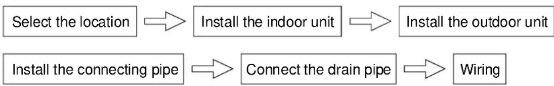
flowchart
graph LR
    A["Select the location"] --> B["Install the indoor unit"]
    B --> C["Install the outdoor unit"]
    D["Install the connecting pipe"] --> E["Connect the drain pipe"]
    E --> F["Wiring"]
ATTACHED FITTINGS
Please check whether the following fittings are of full scope. If there are some attached fittings free from use, please restore them carefully.
| Installation Fittings | Tubing & Fittings |
1. Expansible hook......4?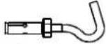 2. Installation hook......4 2. Installation hook......4 3. Installation paper board......1 3. Installation paper board......1 4. Bolt M5×16 or M6×12......4 4. Bolt M5×16 or M6×12......4 | 5. Connecting pipe group......16. Binding tape......6 7. Soundproof / insulation sheath......2 7. Soundproof / insulation sheath......2 |
| Drainpipe Fittings | Protect Pipe Fittings |
8. Out-let pipe sheath......1 9. Out-let pipe clasp......1 9. Out-let pipe clasp......1 10. Tightening band......20[IMAGE]11. Drain elbow......1 10. Tightening band......20[IMAGE]11. Drain elbow......1 12. Seal ring......1 12. Seal ring......1 | 13. Wall conduit......114. Wall conduit cover......1[IMAGE] |
| Others | |
| 19. Owner's manual......120. Installation manual......1 | |
| Remote controller & Its Frame | |
15. Remote controller......1[HTTS]16. Frame......1[GT6Z]17. Mounting screw(ST2.9×10-C-H)......2[DSXG]18. Alkaline dry batteries (AM4)......2 |
INSTALLATION PLACE
CAUTIONS
Location in the following places may cause malfunction of the machine.(If unavoidable, please consult your local dealer)
a. There is petrolatum existing.
b. There is salty air surrounding (near the coast).
c. There is caustic gas (the sulfide, for example) existing in the air (near a hot spring).
d. The Volt vibrates violently (in the factories).
e. In buses or cabinets.
f. In kitchen where it is full of oil gas.
g. There is strong electromagnetic wave existing.
h. There are inflammable materials or gas.
i. There is acid or alkaline liquid evaporating.
j. Other special conditions.
NOTICES BEFORE INSTALLATION
- Select the correct carry-in path.
- Move this unit as originally packaged as possible.
- If the air conditioner is installed on a metal part of the building, it must be electrically insulated according to the relevant standards to electrical appliances.
1. The indoor unit
- There is enough room for installation and maintenance.
- The ceiling is horizontal, and its structure can endure the weight of the indoor unit.
- The air outlet and the air inlet are not impeded, and the influence of external air is the least.
- The air flow can reach throughout the room.
- The connecting pipe and drainpipe could be extracted out easily.
• There is no direct radiation from heaters.
2. The outdoor unit
- There is enough room for installation and maintenance.
- The air outlet and the air inlet are not impeded, and can not be reached by strong wind.
- It must be a dry and well ventilating place.
- The support is flat and horizontal and can stand the weight of the outdoor unit. And will no additional noise or vibration.
- Your neighborhood will not feel uncomfortable with the noise or expelled air.
- There is no leakage of combustible air.
- It is easy to install the connecting pipe or cables.
- Determine the air outlet direction where the discharged air is not blocked.
- A place free of a leakage of combustible gases.
In the case that the installation place is exposed to a strong wind such as a seaside or high position, secure the normal fan operation by putting the unit lengthwise along the wall or using a duct or shield plates.
- If possible, do not install the unit where it is exposed to direct sunlight.
- If necessary, install a blind that does not interfere with the air flow.
- During the heating mode, the water drained off the outdoor unit, The condensate should be well drained away by the drain hole to an appropriate place, so as not to interfere other people or public.
- Select the position where it will not be subject to snow drifts, accumulation of leaves or other seasonal debris. It is important that the air flow for the outdoor unit is not impeded as this will result in reduction in heating or cooling performance.
INDOOR UNIT INSTALLATION
1. Install the main body
A. The existing ceiling (to be horizontal)
a. Please cut a quadrangular hole of 880 × 880mm in the ceiling according to the shape of the installation paper board. (Refer to Chart3, 4)
- The center of the hole should be at the same position of that of the air conditioner body.
- Determine the lengths and outlets of the connecting pipe, drainpipe and cables.
- To balance the ceiling and to avoid vibration, please enforce the ceiling when necessary.
b. Please select the position of installation hooks according to the hook holes on the installation board.
- Drill four holes of 12mm , 45 50mm deep at the selected positions on the ceiling. Then embed the expansible hooks (fittings).
- Face the concave side of the installation hooks toward the expansible hooks. Determine the length of the installation hooks from the height of ceiling, then cut off the unnecessary part.
- If the ceiling is extremely high, please determine the length of the installation hook according to facts.
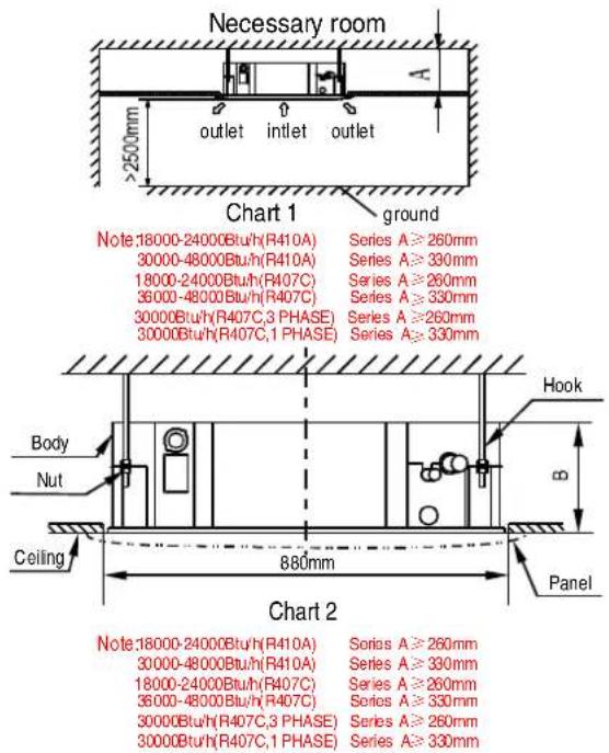
text_image
Necessary room >2500mm outlet intlet outlet Chart 1 ground Note:18000-24000Btu/h(R410A) Series A≥260mm 30000-48000Btu/h(R410A) Series A≥330mm 18000-24000Btu/h(R407C) Series A≥260mm 36000-48000Btu/h(R407C) Series A≥330mm 30000Btu/h(R407C,3 PHASE) Series A≥260mm 30000Btu/h(R407C,1 PHASE) Series A≥330mm Hook Body Nut Ceiling 880mm Panel Chart 2 Note:18000-24000Btu/h(R410A) Series A≥260mm 30000-48000Btu/h(R410A) Series A≥330mm 18000-24000Btu/h(R407C) Series A≥260mm 36000-48000Btuh/R407C) Series A≥330mm 30000Btu/h(R407C,3 PHASE) Series A≥260mm 30000Btu/h(R407C,1 PHASE) Series A≥330mm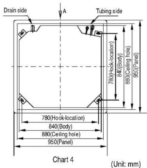
text_image
Drain side A Tubing side 780(Hock-location) 840(Body) 880(Ceiling hole) 950(Panel) 780(Hook-location) 840(Body) 880(Ceiling hole) 950(Panel) Chart 4 (Unit: mm)
text_image
>1000mm >1000mm >1000mm >1000mm Chart 3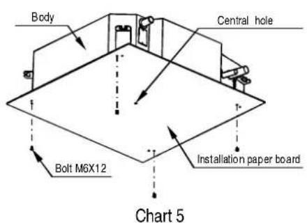
text_image
Body Central hole Bolt M6X12 Installation paper board Chart 5The length could be calculated from Chart5
Length=H-181+L (in general, L=100mm and is half of the whole length of the installation hook)
c. Please adjust the hexangular nuts on the four installation hooks evenly, to ensure the balance of the body.
- If the drainpipe is awry, leakage will be caused by the malfunction of the water-level switch.
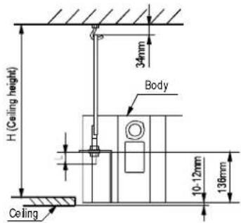
- Adjust the position to ensure the gaps between the body and the four sides of ceiling are even. The body's lower part should sink into the ceiling for 10\~12 mm (Refer to chart 5).
- Locate the air conditioner firmly by wrenching the nuts after having adjusted the body's position well.
text_image
H (Ceiling height) 34mm Body 10-12mm 138mm CeilingChart6
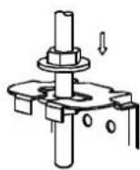
Chart7
B. New built houses and ceilings
a. In the case of new built house, the hook can be embedded in advance (refer to the A.B mentioned above). But it should be strong enough to bear the indoor unit and will not become loose because of concrete shrinking.
b. After installing the body, please fasten the installation paper board onto the air conditioner with bolts(M6×12) to determine in advance the sizes and positions of the hole opening on ceiling.
- Please first guarantee the flatness and horizontal of ceiling when installing it.
• Refer to the A.a mentioned above for others.
c. Refer to the A.c mentioned above for installation.
d. Remove the installation paper board.
CAUTIONS
After completion of installing the body, the four bolts(M6×12) must be fastened to the air conditioner to ensure the body is grounded well.
2. Install The Panel
CAUTIONS
- Never put the panel face down on floor or against the wall, or on bulgy objects.
- Never crash or strike it.
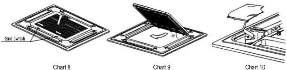
(1) Remove the inlet grid.
a. Slide two grid switches toward the middle at the same time, and then pull them up. (Refer to chart 8)
b. Draw the grid up to an angle of about 45^ , and remove it. (Refer to chart 9)
(2) Remove the installation covers at the four corners.
Wrench off the bolts, loose the rope of the installation covers, and remove them. (Refer to chart 10)
(3) Install the panel
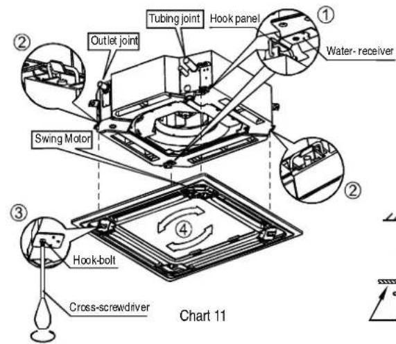
a. Align the swing motor on the panel to the tubing joints of the body properly. (Refer to chart 11)
b. Fix hooks of the panel at swing motor and its opposite sides to the hooks of corresponding water receiver. (Refer to chart 11①) Then hang the other two panel hooks onto corresponding hangers of the body. (Refer to chart 11②)
CAUTIONS
Do not coil the wiring of the swing motor into the seal sponge.
c. Adjust the four panel hook screws to keep the panel horizontal, and screw them up to the ceiling evenly. (Refer to chart 11③)
d. Regulate the panel in the direction of the arrow in Chart11 ④ slightly to fit the panel's center to the center of the ceiling's opening. Guarantee that hooks of four corners are fixed well.
e. Keep fastening the screws under the panel hooks, until the thickness of the sponge between the body and the panel's outlet has been reduced to about 4\~6mm. The edge of the panel should contact with the ceiling well. (Refer to chart 12)
- Malfunction described in Chart13 can be caused by inappropriate tightness the screw.
- If the gap between the panel and ceiling still exists after fastening the screws, the height of the indoor unit should be modified again. (Refer to chart 14-left)
- You can modify the height of the indoor unit through the openings on the panel's four corners, if the lift of the indoor unit and the drainpipe is not influenced (refer to chart 14-right).
(4) Hang the air-in grid to the panel, then connect the lead terminator of the swing motor and that of the control box with corresponding terminators on the body respectively.
(5) Relocate the air-in grid in the procedure of reversed order.
(6) Relocate the installation cover.
a. Fasten the rope of installation cover on the bolt of the installation cover. (Refer to chart 15-left)
b. Press the installation cover into the panel slightly. (Refer to chart 15-right)
text_image
Tubing joint Hook panel Outlet joint Water- receiver Swing Motor Hook-bolt Cross-screwdriver Chart 11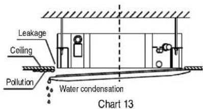
text_image
Leakage Ceiling Pollution Water condensation Chart 13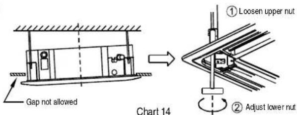
text_image
Gap not allowed Chart 14 ① Loosen upper nut ② Adjust lower nut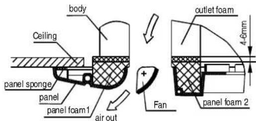
text_image
body Ceiling panel sponge panel panel foam1 air out outlet foam 4-6mm Fan panel foam 2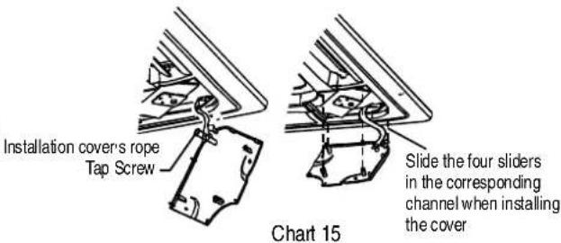
text_image
Installation covers rope Tap Screw Slide the four sliders in the corresponding channel when installing the cover Chart 15Chart 12
OUTDOOR UNIT INSTALLATION
CAUTIONS
- Keep this unit away from direct radiation of the sun or other heaters.
- If unavoidable, please cover it with a shelter.
- In places near coast or with a high attitude where the wind is violent, please install the outdoor unit against the wall to ensure normal performance.
Use a baffle when necessary.
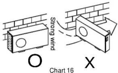
- In the case of extremely strong wind, please prevent the air from flowing backwards into the outdoor unit. (Refer to chart 16)
- Locate the outdoor unit as close to the indoor unit as possible.
- The minimum distance between the outdoor unit and obstacles described in the installation chart does not mean that the same is applicable to the situation of an airtight. Leave open two of three directions A,B,C..
text_image
Strong wind O Chart 16 XNECESSARY ROOM FOR INSTALLATION AND MAINTENANCE
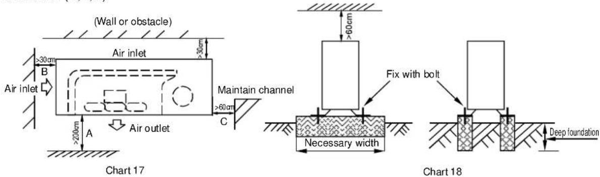
(Refer to chart 17,chart 18)
If possible, please remove the obstacles nearby to prevent the performance from being impeded by too little of air circulation.
The minimum distance between the outdoor unit and obstacles described in the installation chart does not mean that the same is applicable to the situation of an airtight room. Leave open two of the three directions (A,B,C)
text_image
(Wall or obstacle) Air inlet >30cm B Air inlet >200cm A Air outlet >30cm C Maintain channel >60cm >60cm Fix with bolt Necessary width Deep foundation Chart 17 Chart 18MOVING AND INSTALLING
- Since the gravity center of this unit is not at its physical center, so please be careful when lifting it with a sling.
- Never hold the air-in of the outdoor unit to prevent it from deforming.
Do not touch the fan with hands or other objects.
- Do not lean it more than 45^ , and do not lay it sidelong.
- Please fasten the feet of this unit with bolts firmly to prevent it from collapsing in case of earthquake or strong wind.
• Make concrete foundation of the size of 590*328.(Refer to chart 18)
INSTALL THE CONNECTING PIPE
CAUTIONS
Check whether the height drop between the indoor unit and outdoor unit, the length of refrigerant pipe, and the number of the bends meet the following requirements:
The max height drop....20m
(If the height drop is more than 10m, you had better put the outdoor unit over above the indoor unit.)
The length of refrigerant pipe....less than 30m
The number of bends....less than 15
CAUTIONS
- Do not let air, dust, or other impurities fall in the pipe system during the time of installation.
- The connecting pipe should not be installed until the indoor and outdoor units have been fixed already.
- Keep the connecting pipe dry, and do not let moisture in during installation.
The Procedure of Connecting Pipes
- Measure the necessary length of the connecting pipe, and make it by the following way. (Refer to "Connect The Pipes" for details)
1) Connect the indoor unit at first, then the outdoor unit.
- Bend the tubing in proper way. Do not harm to them.
CAUTION
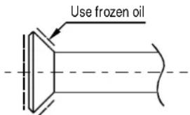
- Daub the surfaces of the flare pipe and the joint nuts with frozen oil, and wrench it for 3\~4 rounds with hands before fasten the flare nuts.(Refer to chart 19)
- Be sure to use two wrenches simultaneously when you connect or disconnect the pipes.
text_image
Use frozen oilChart 19
Bend the pipe with thumb

min-radius 100mm
Chart 20
Make the end straight
Chart 21
2) The stop value of the outdoor unit should be closed absolutely (as original state). Every time you connect it, first loosen the nuts at the part of stop value, then connect the flare pipe immediately (in 5 minutes). If the nuts have been loosened for a long time, dusts and other impurities may enter the pipe system and may cause malfunction later. So please expel the air out of the pipe with refrigerant (R407C) before connection.
3) Expel the air (refer to the "Expel The Air") after connecting the refrigerant pipe with the indoor unit. Then fasten the nuts at the repair-points.
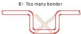
Notices For Bendable Pipe
- The bending angle should not exceed 90^ .
- Bending position is preferably in the middle of the bendable pipe. The larger the bending radius the better it is.
- Do not bend the pipe more than three times.
Bend the connecting pipe of small wall thickness ( 9.53mm)
- Cut out a desired concave at the bending part of the insulating pipe.
- Then expose the pipe (cover it with tapes after bending).
• To prevent collapsing or deforming, please bend the pipe at its biggest radius.
• Use bender to get a small radius pipes.
Use the market brass pipe
- Be sure to use the same insulating materials when you buy the brass pipe (more than 9mm thick).
- Locate The Pipes
- Drill a hole in the wall (suitable just for the size of the wall conduit, 53, 71 series diameter is 90mm, and 120,105,140 series diameter is 105 in general), then set on the fittings such as the wall conduit and its cover.
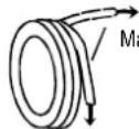
- Bind the connecting pipe and the cables together tightly with binding tapes. Do not let air in, which will cause water leakage by condensation.
-
Pass the bound connecting pipe through the wall conduit from outside. Be careful of the pipe allocation to do no damage to the tubing.
-
Connect the pipes.
-
Then, open the stem of stop values of the outdoor unit to make the refrigerant pipe connecting the indoor unit with the outdoor unit in fluent flow.
-
Be sure of no leakage by checking it with leak detector or soap water.
-
Cover the joint of the connecting pipe to the indoor unit with the soundproof / insulating sheath (fittings), and bind it well with the tapes to prevent leakage.
Flaring
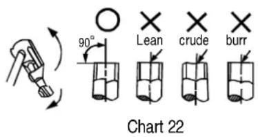
text_image
90° Lean crude burr Chart 22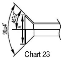
- Cut a pipe with a pipe cutter.
- Insert a flare nut into a pipe and flare thepipe.
| Outside-diameter (mm) | A(mm) | |
| Max Min | ||
| 6.35 | 8.3 | 8.3 |
| 9.53 | 12.4 | 12.0 |
| 12.7 | 15.8 | 15.4 |
| 16 | 19.0 | 18.6 |
| 19 | 23.3 | 22.9 |
Fasten the nuts
- Put the connecting tubing at the proper position, wrench the nuts with hands, then fasten it with a wrench. (Refer to Chart24)
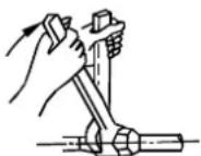
Chart 24
CAUTIONS
Too large torque will harm the bellmouthing and too small will cause leakage. Please determine the torque according to Table 2.
| Tubing Size | Torque |
| 6.35φ | 1420~1720 N·cm (144~176kgf·cm) |
| φ9.53 | 3270~3990 N·cm (333~407kgf·cm) |
| φ12.7 | 4950~6030 N·cm (504~616kgf·cm) |
| φ166 | 6180~7540 N·cm (630~770kgf·cm) |
| φ199 | 9720~11860 N·cm (990~1210kgf·cm) |
Table2 (kg)
Necessary Refrigerant Stow Capacity
| LENGTH(L) Capacity | 18000-24000Btu/h | 30000-48000Btu/h |
| Less than 8m (one-way) | —— | —— |
| Added Refrigerant When Over 8m(one-way) | 65g × (L-8)m | |
Table3
- Please record and reserve well the refrigerant stow capacity of your air conditioner for later maintenance.
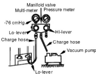
Expel the air with a vacuum pump
( Refer to Chart 25)
(please refer to its manual for the way of using manifold value)
- Loosen and remove the maintenance nuts of stop values A and B, and connect the charge hose of the manifold value with the maintenance terminator of stop value A. (Be sure that stop values A and B are both closed)
- Connect the joint of the charge hose with the vacuum pump.
- Open the Lo-lever of the manifold value completely.
- Turn on the vacuum pump. At the beginning of pumping, loosen the maintenance terminator nut of stop value B a little to check whether the air comes in (the sound of the pump changes, and the indicator of compound meter turns below zero). Then fasten the nut.
-
When the pumping has finished, close the Lo-lever of the manifold value completely and turn off the vacuum pump.
-
When you have pumped for over 15 minutes, please confirm that the indicator of multi-meter is on 1.0 × 10^-5 ~Pa(-76 ~cmHg) .
- Loosen and remove the quadrangle cover of stop values A and B to open stop value A and B completely, then fasten them.
- Disassemble the charge hose from the repair-mouth of stop value A, and fasten the nut.
text_image
Manifold valve Multi-meter | Pressure meter -76 cmHg Lo-lever Charge hose HI-lever Charge hose Vacuum pump Lo-leverChart 25
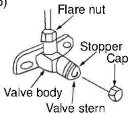
CAUTIONS
All the stop values should be opened before test operation. Each air conditioner has two stop values of different sizes on the side of the outdoor unit which operate as Lo-stop value and Hi-stop value, respectively. (Refer to Chart 26)
text_image
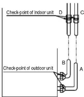
Flare nut Stopper Cap Valve body Valve sternCHECK THE LEAKAGE
Check all the joints with the leak detector or soap water. (refer to Chart 29)
NOTE: in the chart
A.....Lo-stop value
B......Hi-stop value
C,D......Joints of the connecting pipe to the indoor unit.
text_image
Check-point of indoor unit D C Check-point of outdoor unit B AChart 27
INSULATION
Be sure to with insulating materials cover all the exposed parts of the flare pipe joints and refrigerator-
- ant pipe on the liquid-side and the gas-side. Ensure that there is no gap between them.
- Incomplete insulation may cause water condensation.
CONNECT THE DRAIN PIPE
1. Install the drainpipe of the indoor unit
- You can use a polyethylene tube as the drainpipe (out-dia.37-39mm, in-dia.32mm). It could be bought at local market or from your dealer.
- Set the mouth of the drainpipe onto the root of the body's pump-pipe, and clip the drainpipe and the out-let pipe sheath (fittings) together firmly with the out-let pipe clasp (fitting).
CAUTIONS: Use your strength carefully to prevent the pump-pipe from breaking.
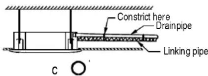
- The body's pump pipe and the drainpipe (especially the indoor part) should be covered evenly with the out-let pipe sheath (fittings) and be bound tightly with the constrictor to prevent condensation caused by entered air.
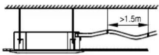
- To prevent water from flowing backwards into the air conditioner while the air conditioner stops, please lean the drainpipe down toward outdoor (outlet-side) at a degree of over 1/50. And please avoid any bulge or water deposit.( Refer to Chart 28.a)
- Do not drag the drainpipe violently when connecting to prevent the body from being pulled. Meanwhile, one support-point should be set every 1\~1.5m to prevent the drainpipe from yielding (Refer to Chart 28.b). Or you can tie the drainpipe with the connecting pipe to fix it.(Refer to Chart 28.c)
- In the case of prolonged drainpipe, you had better tighten its indoor part with a protection tube to prevent it from loosing.
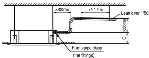
- If the outlet of the drainpipe is higher than the body's pump joint, the pipe should be arranged as vertically as possible. And the lift distance must be less than 200mm, otherwise the water will overflow when the air conditioner stops.( Refer to Chart 29)
- The end of the drainpipe should be over 50mm higher than the ground or the bottom of the drainage chute, and do not immerse it in water. If you discharge the water directly into sewage, be sure to make a U-form aquaseal by bending the pipe up to prevent the smelly gas entering the house through the drain pipe.
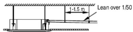
text_image
1-1.5 m Lean over 1/50a O
b ×
text_image
Constrict here Drainpipe Linking pipe c'Chart 28
text_image
>200mm >1-1.5 m Lean over 1/50 >200mm C Pump-pipe clasp (the fittings)Chart 29
2. Drainage test
- Check whether the drainpipe is unhindered
- New built house should have this test done before paving the ceiling.
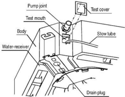
1) Remove the test cover, and stow water of about 2000ml to the water receiver through the stow tube. (Refer to Chart 30)
text_image
Pump joint Test mouth Body Water-receiver Test cover Stow tube Drain plugChart 30
2) Turn on the power, and operate the air conditioner under the "COOLING" mode. Listen to the sound of the drain pump. Check whether the water is discharger well (a lag of 1min is allowed before discharging, according to the length of the drain pipe), and check whether water leaks from the joints.
CAUTIONS: If there is any malfunction, please resolve it immediately.
3) Stop the air conditioner, turn off the power, and reset the test cover to its original position.
- The drain plug is used to empty the water-receiver for maintenance of the air conditioner. Please stuff it imposition at all times during operation to avoid leakage.
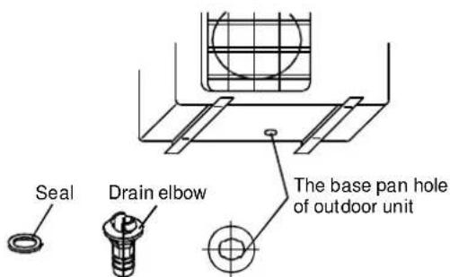
3. Drain Elbow Installation
Fit the seal into the drain elbow, then insert the drain elbow into the base pan hole of outdoor, rotate 90^ to securely assemble them. Connect the drain elbow with an extension drain hose (Locally purchased), in case of the condensate draining off the outdoor unit during the heating mode.
text_image
Seal Drain elbow The base pan hole of outdoor unit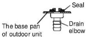
Chart 31
Installation of Flange and duc
Fresh air is intaken by indoor fan motors or ductable fan motor devices on field. The positions of fresh air intake can be changed according to the installation of ductable fan motor.
text_image
57 φ75 96 80 4- Φ 6 Hole 80 96Note:
-
The device can be installed in ceiling cassette type indoor units (several-direction flow).
-
When installing the device, duct is needed on field and the rated diameter is 75mm.
When metal duct pass through wooden wall, electric insulation must be add between duct and wall.
The duct must be pulled out downside to prevent rain and water entering.
Net cover must be set at places where duct explodes to outdoor air to prevent birds and animals entering.
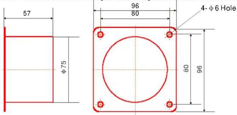
For different type of indoor units, the installation methods are different and the position of holes are different.
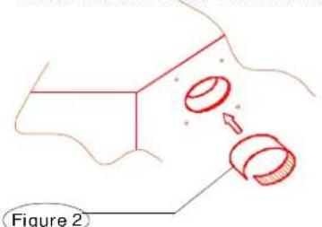
- Removal the hole on the board.
text_image
Installation Type 1 The hole is oppose to drainage pipe Drainage pipe Refrigerant Pipe Hole Insulation Material(Inside) Board Installation Type 2 The hole is oppose to refrigerant pipe Refrigerant Pipe Drainage pipe Hole Board No insulation material inside. only removal board Removal with Pincher Or Inclsel with knife Removal with Pincher Commissure Insulation Material(Inside) Board Removal with Pincher Commissure BoardStick insulation material 4 at indoor hole
text_image
Figure 2Installation Type 1
Put the insulation material 4 on the interface of the hole as shown in Figure 4, then stick on the inside and surface of the board. The interface of the hole can not have gap.
Stick insulation material at the opening part of the board
Installation Type 2
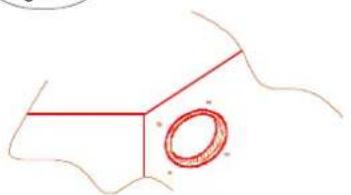
natural_image
Simple line drawing of a mechanical part with a circular feature and curved lines (no text or symbols)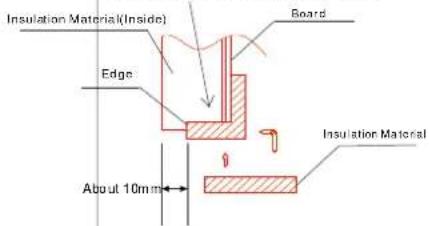
text_image
Insulation Material(Inside) Board Edge Insulation Material About 10mm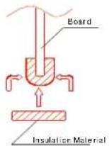
Ensure the interface of insulation material 4 closely contacts with the inside insulation material and the board.
Use screw 2 (M4X12, 4 Pieces) to install flange at the hole, and then stick insulation material 3.
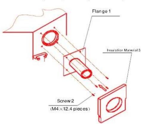
text_image
Flange 1 Insulation Material 3 Screw 2 (M4 × 12.4 pieces)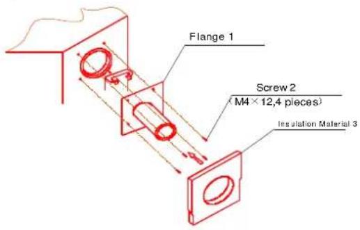
text_image
Flange 1 Screw 2 (M4 × 12,4 pieces) Insulation Material 3Figure 3
Install Duct (the rated diameter: 75 )
- Connect the duct to the flange. (the flange is assembled with the interface of duct.)
- After connection, use the ethylene tape (provided on field) to wrap the joint to prevent air-leakage.
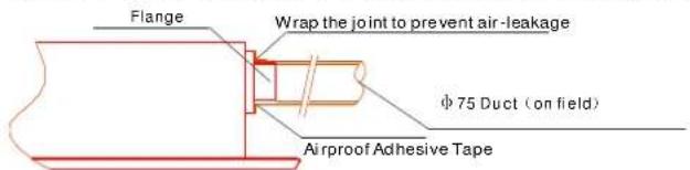
text_image
Flange Wrap the joint to prevent air-leakage φ 75 Duct (on field) Airproof Adhesive TapeNote:
- All ducts must be completely heat-insulated.
- The following phenomenon are not allowed when installing duct:
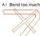
Wrong
Wrong
Wrong
WIRING
CAUTION
- The air conditioner should use separate power supply with rated voltage.
- The external power supply to the air conditioner should have ground wiring, which is linked to the ground wiring of the indoor and outdoor unit.
- The wiring work should be done by qualified persons according to circuit drawing.
- A disconnection device having an air gap contact separation in all active conductors should be incorporated in the fixed wiring according to the National wiring regulation.
- Be sure to locate the power wiring and the signal wring well to avoid cross-disturbance and their contact with connecting pipe or stop value body.
- The wiring attached to this air conditioner is 6m long. Be sure to prolong it with wiring of the same type and proper length if necessary. Generally, do not twist two wiring together unless the joint is soldered well and covered with insulator tape.
-
Do not turn on the power until you have checked carefully after wiring.
-
The Specification of Power
| TYPE(Btu/h) | 18000Btu/h(For R407C and R410A, Heating&Cooling) | 24000Btu/h(For R407C and R410A, Heating&Cooling) | 30000-36000Btu/h(For R407C and R410A, Heating&Cooling) | ||
| POWER | PHASE | 1-PHASE | 1-PHASE | 1-PHASE | |
| FREQUENCY AND VOLT | 220-240V~, 50Hz | 220-240V~, 50Hz | 220-240V~, 50Hz | ||
| CIRCUIT BREAKER/FUSE (A) | 30/25 40/25 | 40/25 | |||
| INDOOR UNIT POWER WIRING( mm^2 ) | 3x1.5 | 3x2.5 | 3x3.5 | ||
| INDOOR/OUTDOOR CONNECTING WIRING( mm^2 ) | GROUND WIRING | 1.5 | 2.5 | 3.5 | |
| OUTDOOR UNIT POWER WIRING | 5x1.5 | 3x2.5 | 3x3.5 | ||
| STRONG ELECTRIC SIGNAL | —— | 3x1.0 | 3x2.5 | ||
| WEAK ELECTRIC SIGNAL | 1-core shield wire1x0.5 | 1-core shield wire1x0.5 | 1-core shield wire1x0.5 | ||
| TYPE(Btu/h) | 24000-3000Btu/(For R407C Heating&Cooling)24000Btu/(For R410A Heating&Cooling) | 36000-4800Btu/(For R407C Heating&Cooling)30000-4800Btu/(For R410A Heating&Cooling) | |||
| POWER | PHASE | 3-PHASE | 3-PHASE | ||
| FREQUENCY AND VOLT | 380V 3N~, 50Hz | 380V 3N~, 50Hz | |||
| CIRCUIT BREAKER/FUSE (A) | 20/15 | 25/15 | |||
| INDOOR UNIT POWER WIRING( mm^2 ) | 5x1.5 | 5x2.5 | |||
| INDOOR/OUTDOOR CONNECTING WIRING( mm^2 ) | GROUND WIRING | 1.5 | 2.5 | ||
| OUTDOOR UNIT POWER WIRING | 5x1.5 | 5x2.5 | |||
| STRONG ELECTRIC SIGNAL | 4x1.0 | 3x1.0 | |||
| WEAK ELECTRIC SIGNAL | 2-core shield wire2x0.5 | ||||
| TYPE(Btu/h) | 18000Btu/h(For R407C and R410A, Cooling only ) | 24000Btu/h(For R407C and R410A, Coding only ) | 30000-36000Btu/h(For R407C and R410A, Coding only ) | ||
| POWER | PHASE | 1-PHASE | 1-PHASE | 1-PHASE | |
| FREQUENCY AND VOLT | 220-240V~, 50Hz | 220-240V~, 50Hz | 220-240V~, 50Hz | ||
| CIRCUIT BREAKER/FUSE (A) | 30/25 | 40/25 | 40/25 | ||
| INDOOR UNIT POWER WIRING( mm^2 ) | 3x2.0 | 3x2.5 | 3x3.5 | ||
| INDOOR/OUTDOOR CONNECTING WIRING( mm^2 ) | GROUND WIRING | 2.0 | 2.5 | 3.5 | |
| OUTDOOR UNIT POWER WIRING | 4x2.0 | 3x2.5 | 3x3.5 | ||
| STRONG ELECTRIC SIGNAL | —— | 2x1.5 | 2x2.5 | ||
| WEAK ELECTRIC SIGNAL | —— | —— | —— | ||
| TYPE(Btu/h) | 24000-30000Btu/h(For R407C, Cooling only )24000 Btu/h(For R410A, Cooling only ) | 36000-48000Btu/h(For R407C, Cooling only )30000-48000Btu/h(For R410A, Cooling only ) | ||
| POWER | PHASE | 3-PHASE | 3-PHASE | |
| FREQUENCY AND VOLT | 380V 3N~, 50Hz | 380V 3N~, 50Hz | ||
| CIRCUIT BREAKER/FUSE (A) | 20/15 | 25/15 | ||
| INDOOR UNIT POWER WIRING( mm^2 ) | 5x1.5 | 5x2.5 | ||
| INDOOR/OUTDOOR CONNECTING WIRING( mm^2 ) | GROUND WIRING | 1.5 | 2.5 | |
| OUTDOOR UNIT POWER WIRING | 5x1.5 | 5x2.5 | ||
| STRONG ELECTRIC SIGNAL | 3x1.5 | 2x1.0 | ||
| WEAK ELECTRIC SIGNAL | 2-core shield wire2x0.5 | |||
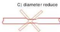
2. Remove the protection board.
Disassemble the bolts from the maintenance board, and pull it in the direction of the arrow to remove the protection board.
Notice: Do not scratch the surface during operation.
text_image
Terminator Protection board Chart 32ATTENTION: Chart 32 is based on the standard model, which may look a little different from your own outdoor unit.
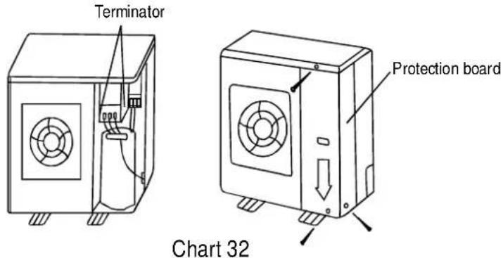
Wiring chart
flowchart
graph TD
    A["Power"] --> B["Switch/Fuse"]
    A --> C["Power linking wiring (indoor)"]
    D["Indoor Unit"] --> E["Outdoor Unit"]
    E --> F["Weak elec-signal link wiring"]
    E --> G["Strong elec-signal link wiring"]
- Please ground air conditioner well. Otherwise, an important grounding may affect anti-jamming performance of whole unit
Chart 33

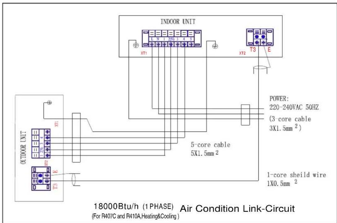
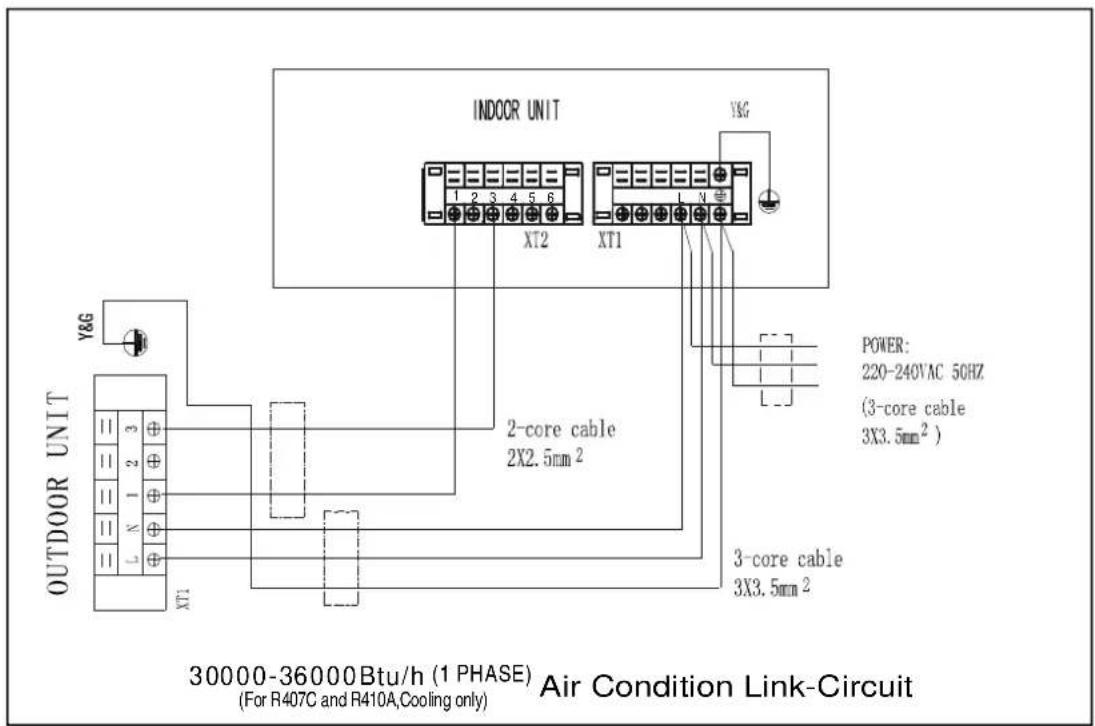
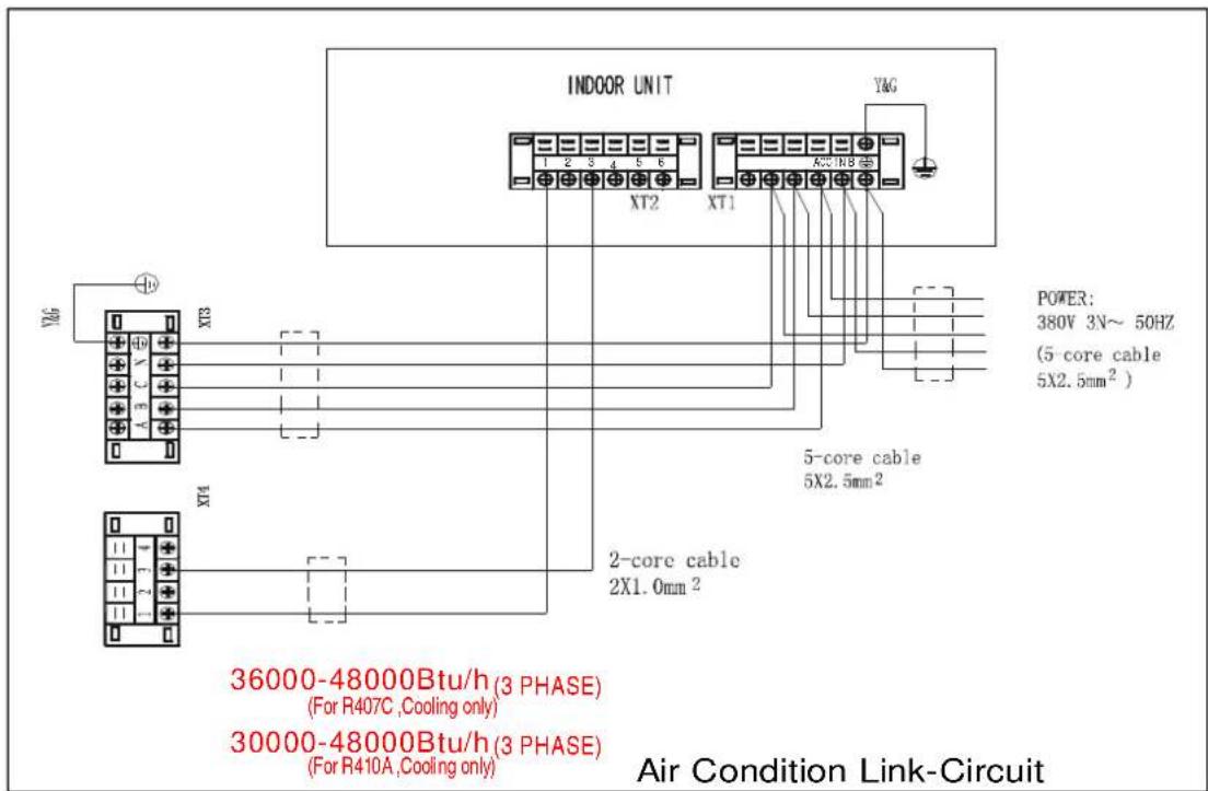
CAUTION: The wiring chart of both cooling only type and cooling& heating type in R22、R407C and R410A series are shown as follows. When wiring, please choose the corresponding chart, or it may cause damage.
text_image
INDOOR UNIT XT1 XT2 XT3 POWERS: 220-240VAC 50HZ (3 core cable 3X1.5mm²) 5-core cable 5X1.5mm² 1-core shield wire 1X0.5mm² OUTDOOR UNIT XT1 XT2 XT3 18000Btu/h (1 PHASE) Air Condition Link-Circuit (For R407C and R410A, Heating&Cooling)Chart 34
text_image
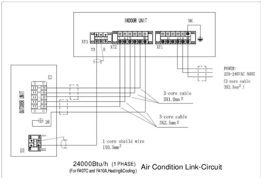
INDOOR UNIT XT3 T3 E XT2 XT1 YAG POWER: 220-240VAC 50HZ (3-core cable 3X2.5mm² ) 3-core cable 3X1.0mm² 3-core cable 3X2.5mm² OUTDOOR UNIT XT3 D O YAG IX2 1-core shield wire 1X0.5mm² 24000Btu/h (1 PHASE) (For R407C and R410A, Heating&Cooling) Air Condition Link-CircuitChart 35
text_image
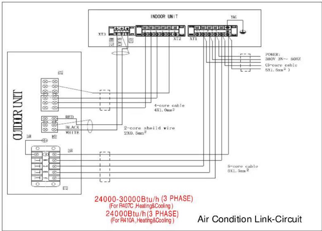
INDOOR UNIT XT3 XT2 XT1 YAG POWER: 380V 3N~ 50HZ (5-core cable 5X1.5mm² ) 4-core cable 4X1.0mm² 2-core shield wire 2X0.5mm² 5-core cable 6X1.5mm² OUTDOOR UNIT RED BLACK WHITE ND 24000-30000Btu/h (3 PHASE) (For R407C, Heating&Cooling ) 24000Btu/h (3 PHASE) (For R410A, Heating&Cooling ) Air Condition Link-CircuitChart36
text_image
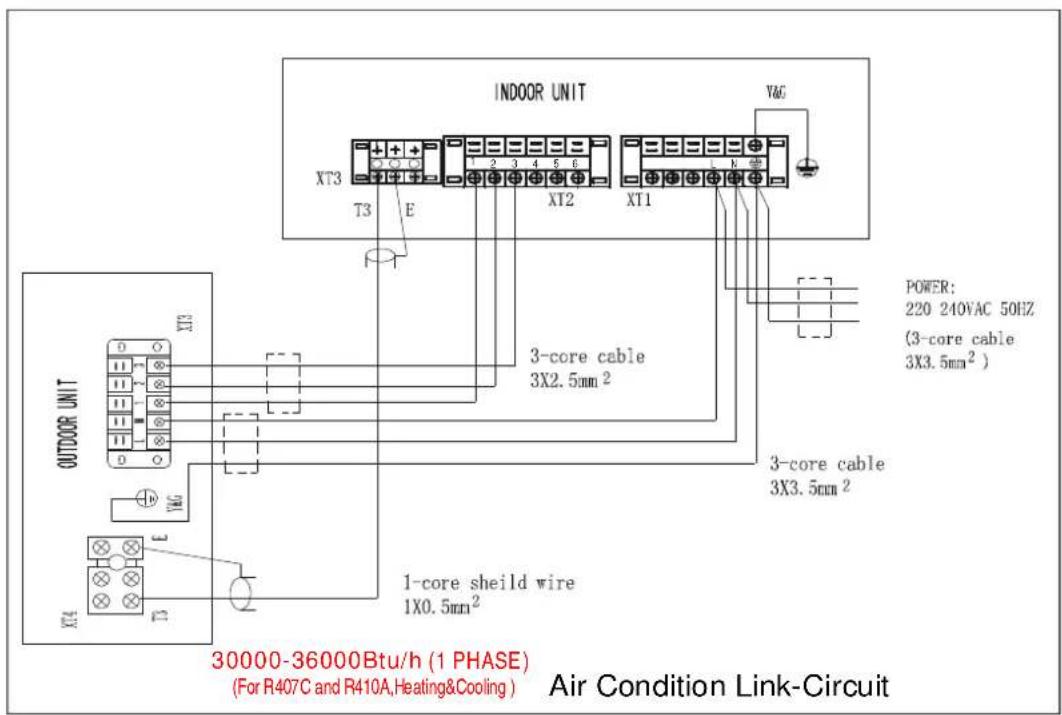
INDOOR UNIT XT3 T3 E XT2 XT1 VAC POWER: 220 240VAC 50HZ (3-core cable 3X3.5mm²) 3-core cable 3X3.5mm² OUTDOOR UNIT XT3 XT4 1-core shield wire 1X0.5mm² 30000-36000Btu/h (1 PHASE) (For R407C and R410A, Heating&Cooling) Air Condition Link-CircuitChart37
text_image
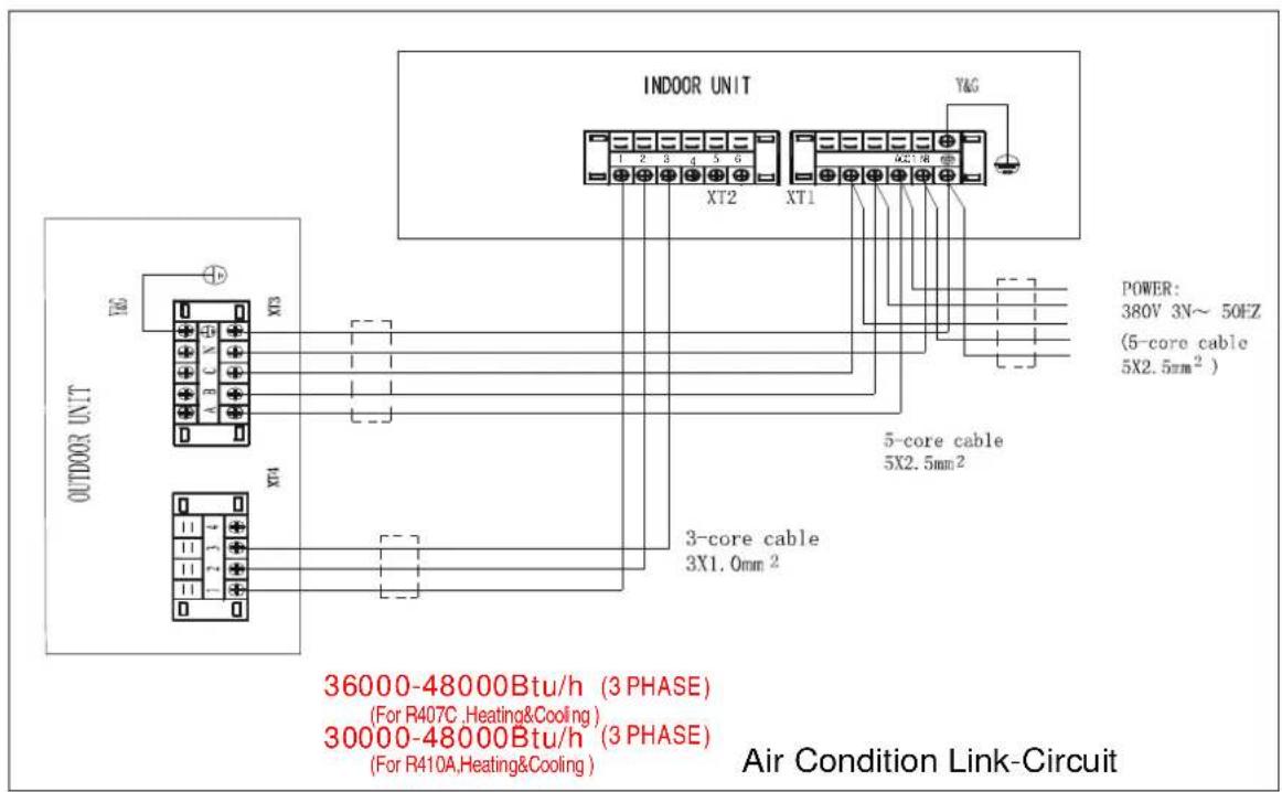
INDOOR UNIT YAG 1 2 3 4 5 6 XT2 XT1 POWER: 380V 3N~ 50HZ (5-core cable 5X2.5mm² ) POWERS: OUTDOOR UNIT XT3 A B C N XT4 3-core cable 3X1.0mm² 5-core cable 5X2.5mm² 36000-48000Btu/h (3 PHASE) (For R407C, Heating&Cooling ) 30000-48000Btu/h (3 PHASE) (For R410A, Heating&Cooling ) Air Condition Link-CircuitChart38
text_image
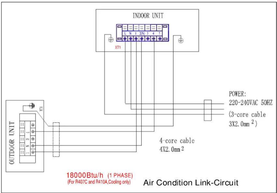
INDOOR UNIT L N 1 2(N) 3 4 5 XT1 OUTDOOR UNIT XT1 POWER: 220-240VAC 50HZ (3-core cable 3X2.0mm²) 4-core cable 4X2.0mm² 18000Btu/h (1 PHASE) (For R407C and R410A, Cooling only) Air Condition Link-CircuitChart 39
text_image
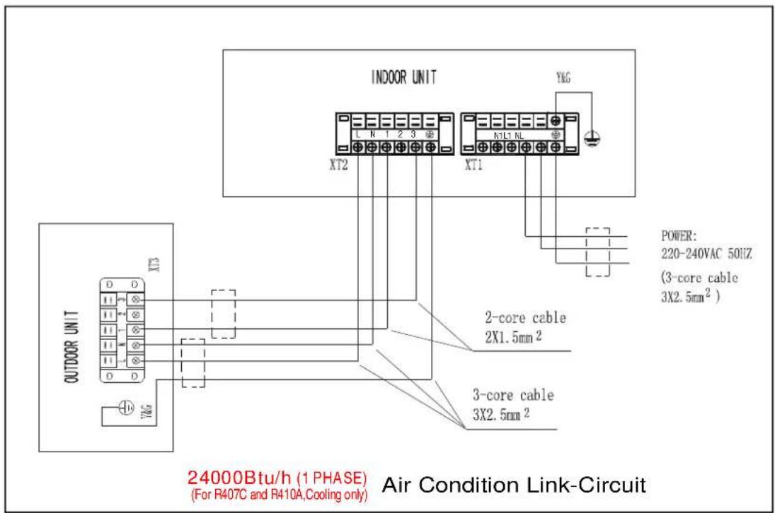
INDOOR UNIT XT2 XT1 Y&G POWER: 220-240VAC 50HZ (3-core cable 3X2.5mm² ) 2-core cable 2X1.5mm² 3-core cable 3X2.5mm² OUTDOOR UNIT XT3 OUTDOOR UNIT 24000Btu/h (1 PHASE) (For R407C and R410A,Cooling only) Air Condition Link-CircuitChart 4 0
text_image
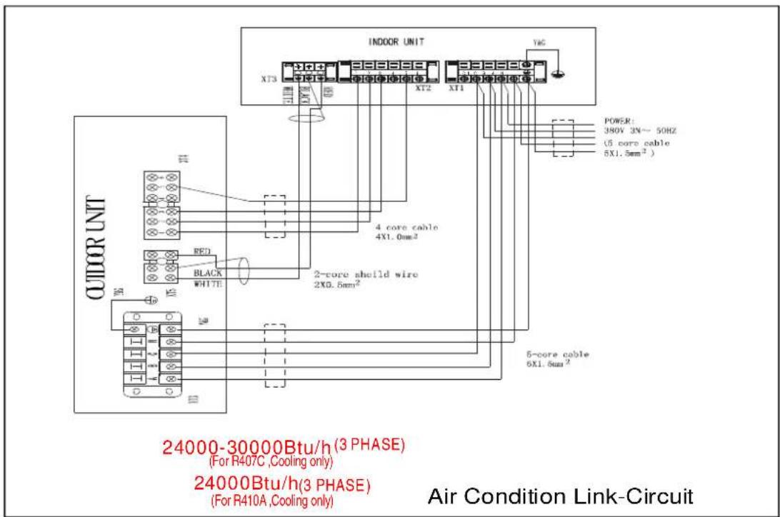
INDOOR UNIT XT3 XT2 XT1 YAG POWER: 390V 3N~50HZ (5 core cable 5X1.5mm²) 4 core cable 4X1.0mm² 2-core shield wire 2X0.5mm² 5-core cable 5X1.5mm² OUTDOOR UNIT RED BLACK WHITE YAG 24000-30000Btu/h (3 PHASE) (For R407C, Cooling only) 24000Btu/h (3 PHASE) (For R410A, Cooling only) Air Condition Link-CircuitChart41
text_image
INDOCR UNIT XT2 XT1 Y&G 2-core cable 2X2.5mm² 3-core cable 3X3.5mm² POWER: 220-240VAC 50HZ (3-core cable 3X3.5mm² ) OUTDOOR UNIT XT1 30000-36000Btu/h (1 PHASE) (For R407C and R410A,Cooling only) Air Condition Link-CircuitChart 42
text_image
INDOOR UNIT YAG 1 2 3 4 5 6 XT2 XT1 ACU1B8 POWER: 380V 3N~ 50HZ (5 core cable 5X2.5mm² ) 5-core cable 5X2.5mm² 36000-48000Btu/h (3 PHASE) (For R407C, Cooling only) 30000-48000Btu/h (3 PHASE) (For R410A, Cooling only) 2-core cable 2X1.0mm² XT3 XT4 Air Condition Link-CircuitChart 43
TEST OPERATION
- The test operation must be carried out after the entire installation has been completed.
-
Please confirm the following points before the test operation:
-
The indoor unit and outdoor unit are installed properly.
- Tubing and wiring are correctly completed.
- The refrigerant pipe system is leakage-checked.
• The drainage is unimpeded.
• The heating insulation works well. - The ground wiring is connected correctly.
- The length of the tubing and the added stow capacity of the refrigerant have been recorded.
- The power voltage fits the rated voltage of the air conditioner.
- There is no obstacle at the outlet and inlet of the outdoor and indoor units.
- The gas-side and liquid-side stop values are both opened.
-
The air conditioner is pre-heated by turning on the power.
-
According to the user's requirement, install the remote controller frame where the remote controller's signal can reach the indoor unit smoothly.
-
Test operation
- Set the air conditioner under the mode of "COOLING" with the remote controller, and check the following points per the "Owner's Manual". If there is any malfunction, please resolve it as per chapter "Troubles And Cause" in the "Owner's Manual".
1) The indoor unit
a. Whether the switch on the remote controller works well.
b. Whether the buttons on the remote controller works well.
c. Whether the air flow louver moves normally.
d. Whether the room temperature is adjusted well.
e. Whether the indicator lights normally.
f. Whether the temporary buttons works well.
g. Whether the drainage is normal.
h. Whether there is vibration or abnormal noise during operation.
I. Whether the air conditioner heats well in the case of the HEATING/COOLING type.
2) The outdoor unit
a. Whether there is vibration or abnormal noise during operation.
b. Whether the generated wind, noise, or condensed of by the air conditioner have influenced your neighborhood.
c. Whether any of the refrigerant is leaked.
CAUTION
A protection feature prevents the air conditioner from being activated for approximately 3 minutes when it is restarted immediately after shut off.
MDV04I-008bW