KT-ES208X12HP8E - NAS Sans Digital - Kostenlose Bedienungsanleitung
Finden Sie kostenlos die Bedienungsanleitung des Geräts KT-ES208X12HP8E Sans Digital als PDF.

Benutzerfragen zu KT-ES208X12HP8E Sans Digital
0 Frage zu diesem Gerät. Beantworten Sie die, die Sie kennen, oder stellen Sie Ihre eigene.
Eine neue Frage zu diesem Gerät stellen
Laden Sie die Anleitung für Ihr NAS kostenlos im PDF-Format! Finden Sie Ihr Handbuch KT-ES208X12HP8E - Sans Digital und nehmen Sie Ihr elektronisches Gerät wieder in die Hand. Auf dieser Seite sind alle Dokumente veröffentlicht, die für die Verwendung Ihres Geräts notwendig sind. KT-ES208X12HP8E von der Marke Sans Digital.
BEDIENUNGSANLEITUNG KT-ES208X12HP8E Sans Digital
ES208X6+B Quick Installation Guide
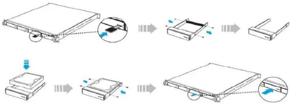
Hard Drive Installation
I. Press the key (included in the package) into the lock slot located at the front of the hard drive tray until the tray handle unlocks.
2. Pull on the tray handle to remove the tray from the enclosure.
3. Dismount the plastic tray protector rods by removing the screws on the sides of the tray.
4. Place the hard drive in the tray, and fasten it with the screws (included in the package) in corresponding locations.
5. Place the tray back into the enclosure and lock the tray by pushing in the tray handle.
flowchart
graph TD
    A["File Attachment"] --> B["Assembly Step 1"]
    B --> C["Assembly Step 2"]
    C --> D["Final Packaging"]
    style A fill:#f9f,stroke:#333
    style D fill:#bbf,stroke:#333
Product Diagrams
Unit Backplane
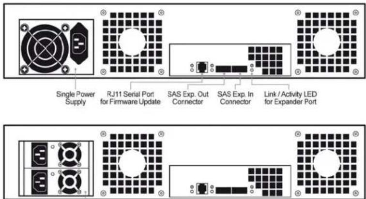
Redundant Power Supplies
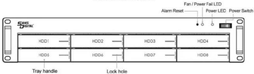
Hard Drive Locations
flowchart
graph TD
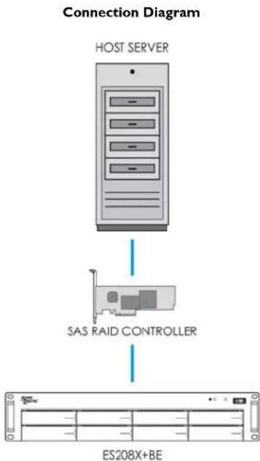
A["HOST SERVER"] --> B["SAS RAID CONTROLLER"]
B --> C["ES208X+BE"]
Redundant Power Supply (Optional)
The redundant power supply feature consists of hot-swappable power supply modules. If one of the power modules fails, the remaining working power supply modules will continue to provide power to the unit so users do not experience downtime. A replacement power supply could be installed while the unit is running. Once the replacement power supply has been installed, the unit will regain its redundant power feature.
Note: Power must be supplied to all power supply modules in order for the redundant feature to operate correctly.
Fan/Power Fail LED Information (Front Panel)
When the power supply modules or internal cooling fan malfunctions, the front fail LED will blink and the alarm will go off. Please see table below:
| Description Alarm Buzzer Fail LED | ||
| Power supply failure Always on Blinking red | ||
| Cooling fan failure Beep with one second interval Blinking red |
Note: Pressing down the 'Alarm Reset' button temporarily silences the alarm. Alarm will start buzzing again once the unit has been restarted.