
MX412 - Mikrofon SHURE - Gratis brugsanvisning og manual
Find enhedens vejledning gratis MX412 SHURE i PDF-format.


Brugerspørgsmål om MX412 SHURE
0 spørgsmål om dette apparat. Besvar dem du kender, eller stil dit eget.
Stil et nyt spørgsmål om dette apparat
Download vejledningen til din Mikrofon i PDF-format gratis! Find din vejledning MX412 - SHURE og tag din elektroniske enhed tilbage i hånden. På denne side er alle dokumenter nødvendige for brugen af din enhed offentliggjort. MX412 af mærket SHURE.
BRUGSANVISNING MX412 SHURE
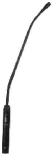
MODEL MX400 SERIES MICROPHONES
natural_image
Simple black curved line with a vertical bar at the end, no text or symbols presentMODEL VARIATIONS
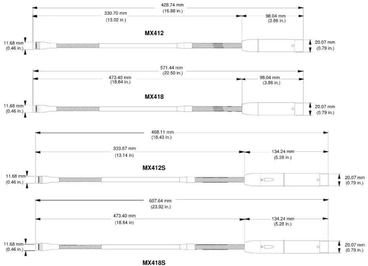
•MX412: 305 mm (12 in.) gooseneck microphone.
•MX418: 457 mm (18 in.) gooseneck microphone.
- MX412S: 305 mm (12 in) gooseneck microphone; includes a mute switch and an LED.
SPECIFICATIONS
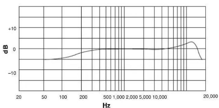
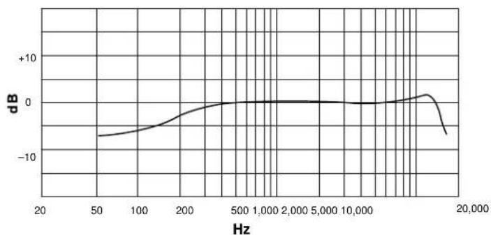
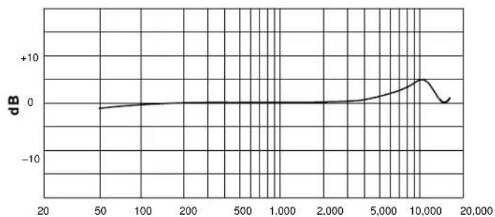
Frequency Response (Figure 1) 50 to 17,000 Hz
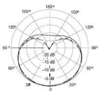
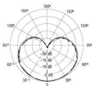
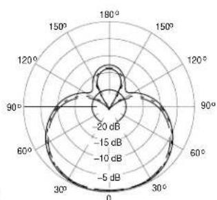
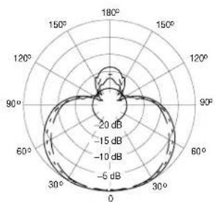
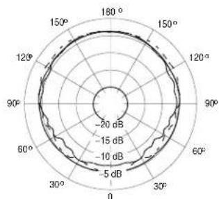
Polar Pattern (Figure 2)
Output Impedance (at 1000 Hz) Rated at 150 Ω (180 Ω actual)
Open Circuit Sensitivity (at 1 kHz, ref. 1 V/Pascal ^* ) Cardioid: -35.0 dB (17.8 mV)
Supercardioid: -33.5 dB (21.1 mV)
Omnidirectional: -27.5 dB (42.2 mV) All settings -12 dB at 0 gain *1 Pascal = 94 dB SPL
Maximum SPL (1 kHz at 1% THD, 1 kΩ load)
Cardioid: 124.2 dB Supercardioid: 122.7 dB
Omnidirectional: 116.7 dB All settings +6 dB at 0 gain
Equivalent Output Noise (A-weighted)
Cardioid: 28.0 dB SPL Supercardioid: 26.5 dB SPL Omnidirectional: 20.5 dB SP
Signal to Noise Ratio (referenced at 94 dB SPL)
Cardioid: 66.0 dB Supercardioid: 67.5 dB Omnidirectional: 73.5 dB
©2002, Shure Incorporated
OVERVIEW
Shure Microflex ^® MX400 Series microphones are miniature gooseneck-mounted electret condenser microphones designed primarily for speech and vocal pickup. They can be mounted on lecterns, pulpits, or conference tables. All models include a preamplifier and are available with interchangeable cardioid, supercardioid, or omnidirectional cartridges.
FEATURES
- Wide dynamic range and frequency response for accurate sound reproduction across the audio spectrum
- Interchangeable cartridges provide the right polar pattern for every application
•Balanced, transformerless output for increased immunity to noise over long cable runs - Shock mount that provides over 20 dB isolation from surface vibration noise
- Locking flange mount for permanently securing microphone to lecterns, pulpits, or conference tables
- Snap-fit foam windscreen
- MX418S: 457 mm (18 in) gooseneck microphone; includes a mute switch and an LED.
Dynamic Range at 1 kΩ Load
96.2 dB
100 dB at 0 gain
Common Mode Rejection 45.0 dB minimum
Mute Switch Attenuation (switched models only) 50.0 dB minimum
Preamplifier Output Clipping Level (1% THD) -6.0 dBV (0.5 V) -12 dB at 0 gain
Polarity
Positive sound pressure on diaphragm produces positive voltage on pin 2 relative to pin 3 of output connector.
Power Requirements
11 to 52 Vdc phantom, 2.0 mA
Environmental Requirements
Operating Temperature Range: -18^ to 57^ ( 0^ to 135^ )
Relative Humidity: 0 to 95%
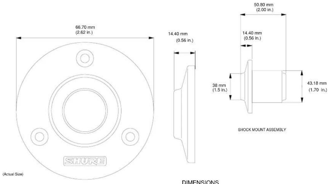
Dimensions (Figure 3)
Certification
Eligible to bear CE Marking. Conforms to European EMC Directive 89/336/EEC. Meets applicable tests and performance criteria in European Standard EN55103 (1996) parts 1 and 2, for residential (E1) and light industrial (E2) environments.
REPLACEMENT PARTS
Foam Ball Windscreen A99WS
Locking Metal Windscreen A412MWS
Portable Desktop Base A412B
Stand Adapter A57E
Omnidirectional Cartridge R183B
Supercardioid Cartridge R184B
Cardioid Cartridge R185B
Snap-fit Foam Windscreen (4) RK412WS
Shock Mount A400SM
line
| Hz | dB | | ------ | ----- | | 20 | -5.0 | | 50 | -3.0 | | 100 | -1.0 | | 200 | 0.0 | | 500 | 0.0 | | 1,000 | 0.0 | | 2,000 | 0.0 | | 5,000 | 0.0 | | 10,000 | 0.0 | | 15,000 | 5.0 | | 20,000 | -5.0 |CARDIOID
radar
| Angle | Value (dB) | |-------|------------| | 0 | 0 | | 30 | -5 | | 60 | -10 | | 90 | -15 | | 120 | -20 | | 150 | -20 | | 180 | -20 |— 250 Hz --- 500 Hz --- 1000 Hz
radar
| Angle | Value (dB) | |-------|------------| | 0 | -20 | | 30 | -15 | | 60 | -10 | | 90 | -5 | | 120 | -10 | | 150 | -15 | | 180 | -20 |2500 Hz 6400 Hz 10000 Hz
CARDIOID
line
| Hz | dB | |-------|--------| | 20 | -5.0 | | 50 | -4.0 | | 100 | -3.0 | | 200 | -1.0 | | 500 | 0.0 | | 1,000 | 0.0 | | 2,000 | 0.0 | | 5,000 | 0.0 | | 10,000| 0.0 | | 15,000| 1.0 | | 20,000| -5.0 |SUPERCARDIOID
radar
| Angle | Value | |---|---| | 0° | -20 dB | | 30° | -15 dB | | 60° | -10 dB | | 90° | -5 dB | | 120° | -10 dB | | 150° | -15 dB | | 180° | -20 dB |— 250 Hz --- 500 Hz --- 1000 Hz
radar
| Angle | Value (dB) | |---|---| | 0 | -20 | | 30 | -15 | | 60 | -10 | | 90 | -5 | | 120 | -10 | | 150 | -15 | | 180 | -20 |2500 Hz 6400 Hz 10000 Hz
SUPERCARDIOID
line
| x | dB | |-------|------| | 20 | -2.0 | | 50 | -1.5 | | 100 | -1.0 | | 200 | -0.5 | | 500 | 0.0 | | 1,000 | 0.0 | | 2,000 | 0.0 | | 5,000 | 2.0 | | 10,000| 8.0 | | 15,000| 2.0 |Hz OMNIDIRECTIONAL

radar
| Angle | Value (dB) | |---|---| | 0° | -20 | | 30° | -15 | | 60° | -10 | | 90° | -5 | | 120° | -10 | | 150° | -15 | | 180° | -20 |— 250 Hz --- 500 Hz — 1000 Hz
radar
| Angle | Value (dB) | |-------|------------| | 0 | -20 | | 30 | -15 | | 60 | -10 | | 90 | -5 | | 120 | -10 | | 150 | -15 | | 180 | -20 |2500 Hz 6400 Hz 10000 Hz
TYPICAL FREQUENCY RESPONSE
Figure 1
OMNIDIRECTIONAL TYPICAL POLAR PATTERNS
Figure 2
text_image
66.70 mm (2.62 in.) 14.40 mm (0.56 in.) 50.80 mm (2.00 in.) 14.40 mm (0.56 in.) 38 mm (1.5 in.) 43.18 mm (1.70 in.) SHOCK MOUNT ASSEMBLY (DActual Size) SHURE DIMENSIONSFigure 3
MOUNTING FLANGE