70-8113 - Ukategoriseret Metra - Gratis brugsanvisning og manual
Find enhedens vejledning gratis 70-8113 Metra i PDF-format.

Brugerspørgsmål om 70-8113 Metra
0 spørgsmål om dette apparat. Besvar dem du kender, eller stil dit eget.
Stil et nyt spørgsmål om dette apparat
Download vejledningen til din Ukategoriseret i PDF-format gratis! Find din vejledning 70-8113 - Metra og tag din elektroniske enhed tilbage i hånden. På denne side er alle dokumenter nødvendige for brugen af din enhed offentliggjort. 70-8113 af mærket Metra.
BRUGSANVISNING 70-8113 Metra
Receiver Wiring Adaptor
IMPORTANT
120 70-8113
Before starting, compare items on your invoice with items received. Thoroughly check packing materials. If an item is missing, please call Crutchfield at 1-888-955-6000.
Revision 03/13/17
STEP 1 -- MATCH & CONNECT WIRES
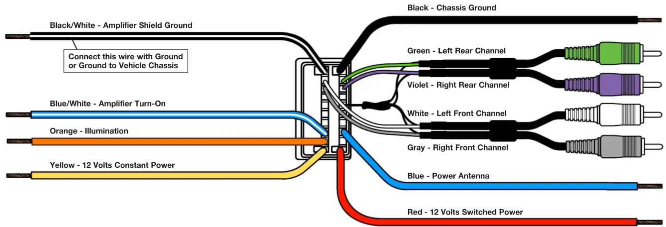
A. Match wires below to the matching function of each wire on your receiver (refer to instructions supplied with receiver). The wire colors of your new receiver may, or may not, match the wire colors of the adaptor. Match adaptor and receiver wires by function, disregarding color.
B. Your receiver illumination wire could be Orange or Orange/White. As with other wires, match this wire to the illumination wire in this harness by function, not by color. If your receiver does not have an illumination wire, tape off the illumination wire.
C. Individually tape off any unused wires.
D. Make final wiring connections following instructions on the next page.
text_image
Black/White - Amplifier Shield Ground Connect this wire with Ground or Ground to Vehicle Chassis Blue/White - Amplifier Turn-On Orange - Illumination Yellow - 12 Volts Constant Power Black - Chassis Ground Green - Left Rear Channel Violet - Right Rear Channel White - Left Front Channel Gray - Right Front Channel Blue - Power Antenna Red - 12 Volts Switched PowerReceiver Wiring Adaptor Connections
120 70-8113
STEP 2 -- CRIMP CONNECTIONS
Tools & Parts Required ▶
Wire Stripper/Crimp Tool Crimp Caps
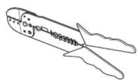
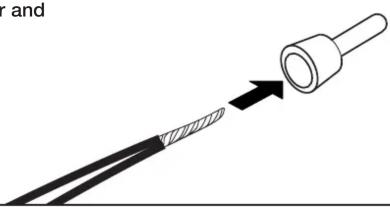
A. Strip wires back 1/2".

natural_image
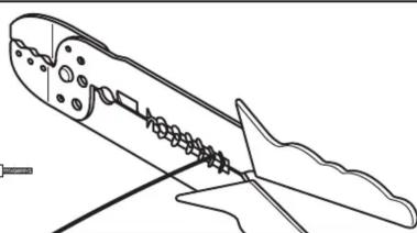
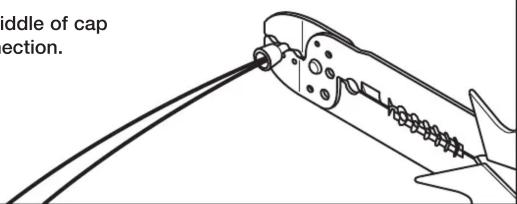
Line drawing of a mechanical component with internal gear-like structure (no text or symbols)B. Twist wires together and insert in crimp cap.
natural_image
Diagram showing a cable being inserted into a plug, with an arrow indicating the insertion direction (no text or symbols present)C. Squeeze middle of cap for tight connection.
text_image
diddle of cap ection.STEP 2 -- CONTINUED
D. Complete crimp connections for all necessary wires.
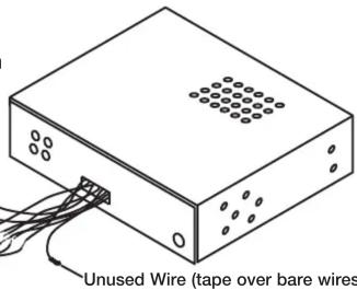
E. Be sure to wrap any wires from the Wiring Adaptor that are not necessary (wires with no match from the new receiver) with electrical tape.
Receiver Wiring Adaptor
Generic Illustration
text_image
Unused Wire (tape over bare wires)STEP 3 -- APPLICATION
When ready to install the receiver, plug the Wiring Adaptor from the new receiver or receiver assembly into the factory radio harness(es) in the vehicle dash.

text_image
to install the receiver, plug aptor from the new receiver sembly into the factory (es) in the vehicle dash.Generic Illustration
CRUTCHFIELD®
Copyright 2017 Crutchfield Corporation