
FS133E270MBU060 - Symaskine Union Special - Gratis brugsanvisning og manual
Find enhedens vejledning gratis FS133E270MBU060 Union Special i PDF-format.

Brugerspørgsmål om FS133E270MBU060 Union Special
0 spørgsmål om dette apparat. Besvar dem du kender, eller stil dit eget.
Stil et nyt spørgsmål om dette apparat
Download vejledningen til din Symaskine i PDF-format gratis! Find din vejledning FS133E270MBU060 - Union Special og tag din elektroniske enhed tilbage i hånden. På denne side er alle dokumenter nødvendige for brugen af din enhed offentliggjort. FS133E270MBU060 af mærket Union Special.
BRUGSANVISNING FS133E270MBU060 Union Special
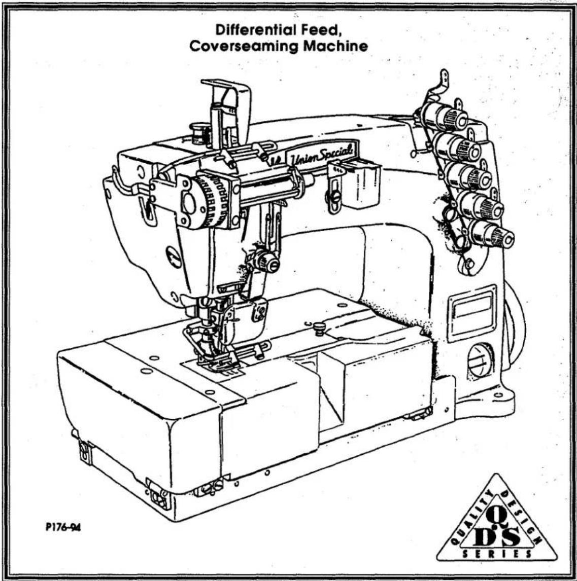
Union Special INDUSTRIAL SEWING EQUIPMENT
ILLUSTRATED PARTS LIST
MANUAL NO. PT9402
STYLES
FS133E270MBU060
PREFACE
This parts manual has been prepared to assist you in locating individual parts or assemblies on FS100 Series machines. It can be used in conjunction with Union Special Adjusting Manual IN9403.
It is the desire of Union Special that each machine run at its optimum performance. Parts listed in this manual are designed specifically for your machine and are manufactured with utmost precision to assure long lasting service.
This manual has been comprised on the basis of available information. Changes in design and/or improvements may incorporate a slight modification of configuration in illustrations or part numbers.
On the following pages are illustrations and terminology used in describing the parts used on FS100 Series machines.
SAFETY RULES

General Operating Directions
The sewing machines described in this instruction manual are prohibited from being put into service until it has been ascertained that the sewing units, in which these sewing machines will be built-in have conformed with the EC Council Directives (89/392/EEC, Annex II B).
- Before putting the machines described in this manual into service, carefully read the instructions. The starting of each machine is only permitted after taking notice of the instructions and by qualified operators.
IMPORTANT! Before putting the machine into service, also read the safety rules and instruction from the motor supplier.
-
Observe the national safety rules valid for your country.
-
Each machine is only allowed to be used as foreseen. The foreseen use of the particular machine is described in paragraph "STYLES OF MACHINES" of this instruction manual. Another use, going beyond the description, is not as foreseen.
-
All safety devices must be in position when the machine is ready for work or in operation. Operation of the machine without the appertaining safety devices is prohibited.
-
The following safety devices are components of the sewing machines: Fingerguard, needle lever eyelet guard, needle bar guard, needle break protection shield and handwheel-belt guard.
-
When gauge parts are exchanged (e.g. needle, presser foot, needle plate, feed dog and bobbin) during threading, when the operator leaves the workplace, and during service work, the machine must be isolated from the main power by switching off the main switch or disconnecting the main plug. On mechanically operated clutch motors without a start inhibitor it is necessary to wait until the motor has stopped.
-
Wear safety glasses.
-
In case of machine conversions and changes all valid safety rules must be considered. Conversions and changes are made at your own risk.
-
Commissioning of the sewing head is prohibited until such time as the entire sewing unit is found to comply with EC regulations.
-
The warning hints in the instructions are marked with one of these two symbols:

Items require special attention
Danger of injury to operative or service staff
Be sure to observe and adhere to these indications and to the generally applicable regulations.
Special Operating Directions
- For the following the machine has to be disconnected from the power supply by turning off the main switch or by pulling out the main plug:
11.1 For threading needle(s), looper, spreader etc.
11.2 For replacing sewing parts such as needle, presser foot, throat plate, looper, spreader, feed dog, needle guard, folder, fabric guide etc.
11.3 When leaving the workplace and when the workplace is unattended.
11.4 For maintenance work.
11.5 When using clutch motors without actuation lock, wait until the motor is stopped totally.
General Maintenance Directions
-
Maintenance, repair and conversion work (see item 8) must be done only by trained technicians or special skilled personnel under consideration of the instructions.
-
Any work on the electrical equipment must be done by an electrician or under direction and supervision of special skilled personnel.
Special Maintenance Directions
-
Work on parts and equipment under electrical tension is not permitted. Permissible exceptions are described in the applicable sections of standard sheet DIN VDE 0105.
-
Before doing maintenance and repair work on the pneumatic equipment, the machine has to be disconnected from the compressed air supply. In case of existing residual air pressure after disconnecting from compressed air supply (e.g. pneumatic equipment with air tank), the pressure has to be removed by bleeding.
Exceptions are only allowed for adjusting work and function checks done by special skilled personnel.
Standards
- The sewing machines described in this manual are built according to the following standards:
EN292-2 Safety of machinery-basic concepts, general principles for design.
IEC204-3-1/EN60204-3-1 Electrical equipment of industrial machines. Part 3: Particular requirements for sewing machines, units and systems.
CONTENTS
IDENTIFICATION OF MACHINES 4
MACHINE STYLES 4
ILLUSTRATIONS 5
NEEDLES 5
TERMS 5
NOTES 8
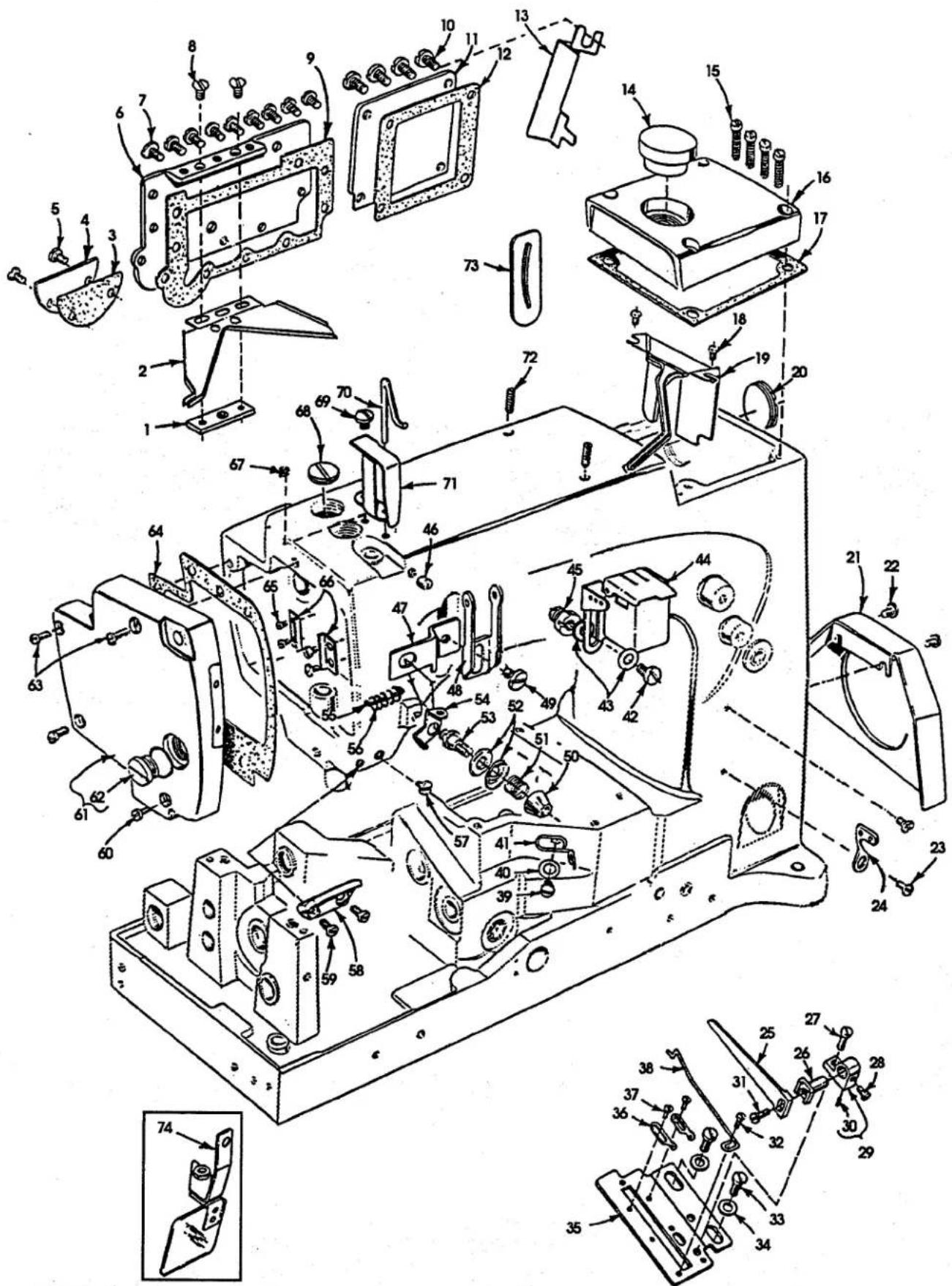
EXPLODED VIEWS
MAIN FRAME, CAST-OFF PLATE & MISCELLANEOUS COVERS....9
MAIN FRAME, CAST-OFF PLATE & MISCELLANEOUS COVERS (CONT.) 11
MAIN FRAME, BUSHINGS, OIL SIGHT GAUGE & MISCELLANEOUS OILING PARTS 13
CRANKSHAFT, NEEDLE LEVER, NEEDLE BAR & LOOPER DRIVING PARTS 15
CRANKSHAFT, NEEDLE LEVER, NEEDLE BAR & LOOPER DRIVING PARTS (CONT.) 17
SPREADER & SPREADER DRIVE....19
LOOPER ROCKER & CONNECTING ROD PARTS 21
MAIN & DIFFERENTIAL FEED MECHANISMS 23
MAIN & DIFFERENTIAL FEED MECHANISMS (CONT.) 25
MAIN SHAFT & KNIFE DRIVING PARTS 27
THREAD TENSION & LIFTER LEVER PARTS....29
COVERS & MISCELLANEOUS PARTS 31
PRESSER FOOT, THROAT PLATE & FEED DOG PARTS 33
STEPPER MOTOR METERING DEVICE & SYNCHRONIZER KIT 35
THREAD STAND & MISCELLANEOUS ACCESSORIES ....37
TAPE REEL ASSEMBLIES 38
NOTES 39
NOTES 40
NUMERICAL INDEX OF PARTS 41
NUMERICAL INDEX OF PARTS 42
NOTES 43
IDENTIFICATION OF MACHINES
Each Union Special machine carries a style number, which on this class machine is stamped in the style plate affixed to the right front of the machine.
The serial number is stamped in the casting at the right rear base of machine.
MACHINE STYLES
FS133E270MBU060
COLLARETTE: Three needle, differential feed, medium capacity with upper elastic metering device (two stage) lower fabric undertrimmer and pneumatic elastic cutter - Typical application - For attaching 3/16" to 1 1/2" wide elastic from a roll, to panties and lingerie. Requires workstation number WS42800BK10A. Seam specifications 605 LSb-1. Standard Gauge Number 060, 15/64" (6.0 mm). Maximum recommended speed 5500 R.P.M. Recommended needle 121GBS, size 080/032.
ILLUSTRATIONS
This manual has been arranged to simplify ordering repair parts. Exploded views of various sections of the mechanism are shown so that the parts may be seen in their actual position in the machine. On the page opposite the illustration will be found a listing of the parts with their part numbers, description and the number of pieces required in the particular view being shown.
Numbers in the first column are reference numbers only, and merely indicate the position of the part in the illustration. The reference number should never be used in ordering parts. Always use the part number listed in the second column.
Component parts of sub-assemblies which can be furnished for repairs are indicated by indenting their descriptions under the description of the main sub-assembly. As an example refer to the following text.
- 29126EC Upper Looper Drive Shaft Assembly 1
- 22503F Screw 1
- 39543E Cam Follower Locking Clamp .... 1
It will be noted in the previous example that the cam follower, bushing, cam guide, and the upper looper drive shaft are not listed. The reason is that replacement of these parts individually is not recommended, so the complete upper looper drive shaft assembly should be ordered.
When a part is common to all machines covered in this manual, no specific usage will be mentioned in the description. However, when the parts for the various machines are not the same, the specific usage will be mentioned in the description and, if necessary, the difference will be shown in the illustration.
A numerical index of all the parts shown in this manual is located at the back. This will facilitate locating the illustration and description when only a part number is known.
IDENTIFYING PARTS
Where the construction permits, each part is stamped with its part number. On some of the smaller parts and on those where construction does not permit, an identification letter is stamped in, to distinguish the part from similar ones.
PLEASE NOTE: Part numbers represent the same part, regardless of which manual they appear. On all orders please include part number, name and style of machine for which the part was ordered.
NEEDLES
Each needle has both a type and size number. The type number denotes the kind of shank, point, length, groove, finish and other details. The size number, stamped on the needle shank, denotes the largest diameter of the blade measured between the shank and the eye. Collectively, the type number and size number represent the complete symbol which is given on the label of all needles packed and sold by Union Special.
TYPE
DESCRIPTION
121 GBS Round shank, round point, short, single groove, struck groove, spotted, ball point, chromium plated. Sizes available 065/025, 070/027, 075/029, 080/032, 090/036, 100/040.
When changing the needle, make sure it is fully inserted in the needle head before the nut is tightened.
To have needles promptly and accurately filled, an empty package, a needle sample, or the type and size number should be forwarded. Use the description on the label. A complete order should read as follows: "100 needles, type 121 GBS, size 070/027".
TERMS
Prices are net cash and subject to change without notice. All shipments are forwarded F.O.B. shipping point. A charge is made to cover postage and insurance.
P165-94
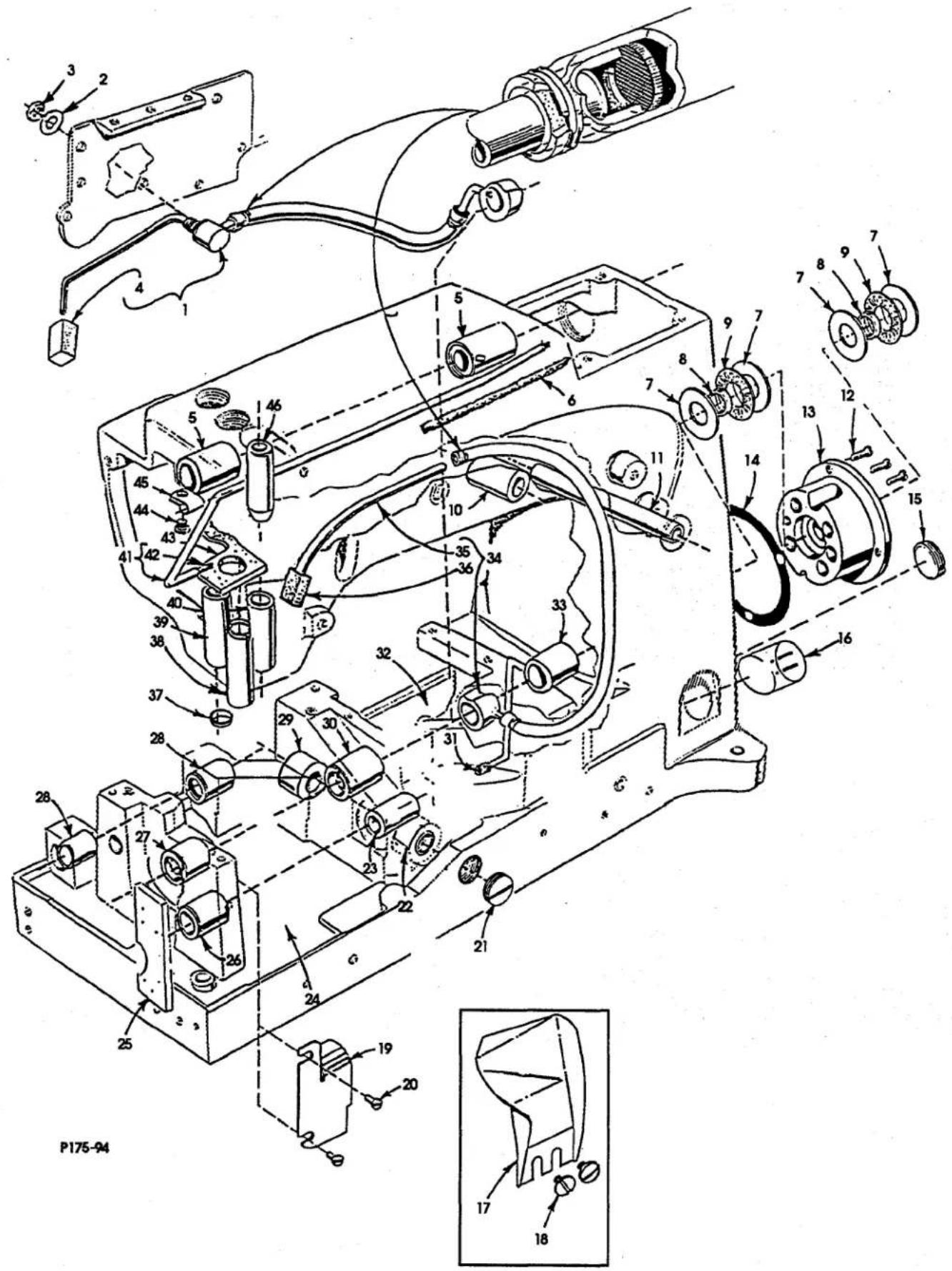
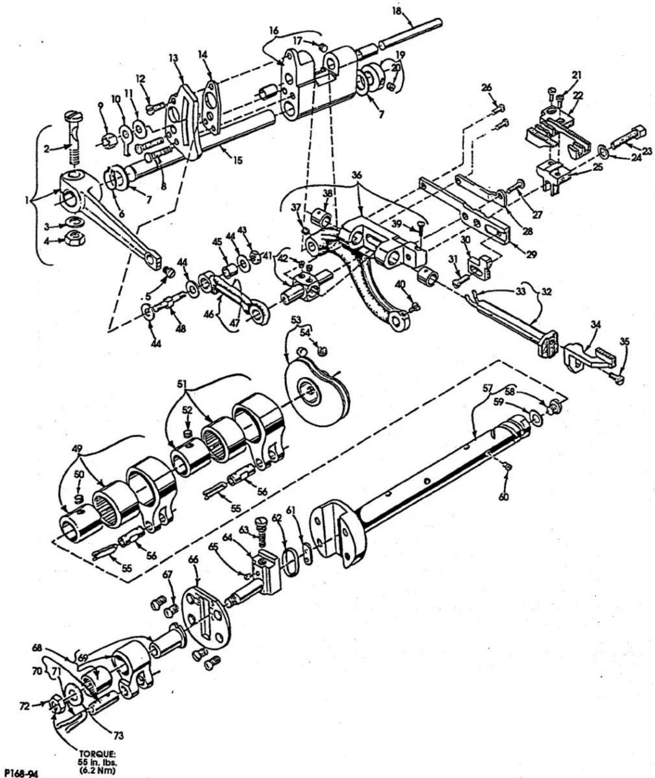
MAIN FRAME, CAST-OFF PLATE & MISCELLANEOUS COVERS
| Ref. | Amt. | ||
| No. | Part No. | Description | Req. |
- 56382Y Block, for oil drip plate .... 1
- 56382AB Oil Drip Plate 1
- 56382K Gasket, for looper drive shaft cover .... 1
- 56382J Cover, for looper drive shaft .... 1
- 22829 Screw, for looper drive shaft cover 2
- 56382AA Oil Reservoir Cover Back .... 1
- 22848 Screw, for oil reservoir cover, back 9
- 22524 Screw, for oil drip plate 2
- 56382L Gasket, for oil reservoir cover, back .... 1
- 22548 Screw, for crank chamber cover, lower 4
- 56382D Crank Chamber Cover Lower 1
- 56382E Gasket, for crank chamber cover, lower....1
- 57795B Synchronizer Bracket .... 1
- 660-1002 Plug, for crank chamber cover, upper .... 1
- 22541C Screw, for crank chamber cover, upper 4
- 57782M Crank Chamber Cover Upper 1
- 56382C Gasket, for crank chamber cover, upper .... 1
- 90 Screw, for bearing oiler assembly 2
- 56382AC Bearing Oiler Assembly 1
- 22539S Plug Screw, for bed .... 1
- 21375CE Belt Guard 1
- 22829 Screw, for belt guard 2
- 98A Screw, for looper guard thread eyelet 2
- 158B Looper Thread Eyelet 1
- 52904B Retaining Finger 1
- 52804E Retainer Support ....1
- 22768 Screw, for retaining finger support .... 1
- 87U Screw, for retainer support .... 1
- 52904E Retaining Finger Support .... 1
- 50-216BLK Pin 1
- 22516 Screw, for retaining finger .... 1
- 73A Screw, for cast off wire .... 1
- 22569C Screw, for support plate 2
- 69H Washer, for support plate screw 2
- 57757B Cast-Off Plate 1
- 52958D Looper Thread Take-Up Eyelet 2
- 73A Screw, for take-up eyelet 2
- 52904G Cast-Off Wire 1
- 22585A Screw 1
- 20 Washer 1
- 53758 Looper Thread Eyelet 1
- 22848 Screw, for lubricator bracket 1
- 20 Washer, for lubricator bracket 1
- 57894D Eyelet, for needle thread lubricator .... 1
- 22889H Adapter Screw, for needle thread frame eyelet .... 1
- 95 Screw 1
- 57844C Eyelet, for mounting plate 1
- 57858 Spreader Thread Eyelet 1
-
22839C Screw 1
-
thru 74. See following page
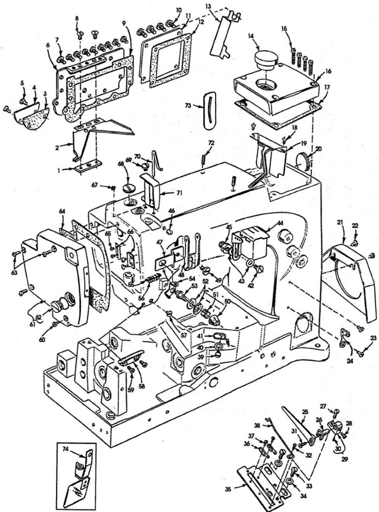
P165-94
MAIN FRAME, CAST-OFF PLATE & MISCELLANEOUS COVERS (CONT.)
Ref.
No. Part No.
Description
Amt.
Req.
- thru 49. See preceding page
| 50. | 57892H | Nut, for spreader thread post | 1 |
| 51. | 57892C5 | Spreader Tension Spring | 1 |
| 52. | 80665F | Disk, for tension post | 2 |
| 53. | 57892J | Spreader Tension Post | 1 |
| 54. | 57844 | Spreader Thread Guide | 1 |
| 55. | 34758 | Needle Thread Guide | 1 |
| 56. | 57858A | Thread Guide Spring | 1 |
| 57. | 22542 | Screw, for spreader thread guide | 1 |
| 58. | 57944B | Needle Thread Guide | 1 |
| 59. | 605A | Screw, for needle thread guide | 2 |
| 60. | 22541C | Screw, for head cover | 2 |
| 61. | 57882M | Head cover | 1 |
| 62. | 22539AB | Plug Screw, for head cover | 1 |
| 63. | 22851D | Screw, for head cover | 2 |
| 64. | 57882L | Gasket, for head cover | 1 |
| 65. | 22564B | Screw, for guide plate | 4 |
| 66. | 34831C | Guide plate | 2 |
| 67. | 22539AA | Plug Screw, for bed | 1 |
| 68. | 22894Y | Set Screw | 1 |
| 69. | 22585A | Screw, for eyelet guard | 1 |
| 70. | 57770 | Needle Thread Take-Up | 1 |
| 71. | 33795 | Guard, for needle thread eyelet | 1 |
| 72. | 22894E | Screw, for needle lever stud | 2 |
| 73. | 660-617 | Gasket, for needle lever eyelet | 1 |
| 74. | 99682XCA | Guard, for needle break | 1 |
MAIN FRAME, BUSHINGS, OIL SIGHT GAUGE & MISCELLANEOUS OILING PARTS
| Ref. No. | Part No. | Description | Amt. Req. |
| 1. | 59493A | Base Oil Pump Assembly | 1 |
| 2. | 660-230 | Gasket | 1 |
| 3. | 258A | Nut | 1 |
| 4. | 666-214 | Felt Intake | 1 |
| 5. | 57849 | Bushing, for spreader rocker shaft | 2 |
| 6. | CL-21 | Oil Wick | 1 |
| 7. | 56390H | Thrust Washer | 4 |
| 8. | 56390J | Pilot Ring | 2 |
| 9. | 660-665 | Needle Thrust Bearing | 2 |
| 10. | 52883R | Bushing, for presser foot lifter | 1 |
| 11. | 21657X | Release Bushing | 1 |
| 12. | 22569B | Screw, for crankshaft bushing housing | 3 |
| 13. | 57890B | Crankshaft Bushing Housing | 1 |
| 14. | 56390E | Gasket, housing | 1 |
| 15. | 22539R | Oil Drain Plug | 1 |
| 16. | 51-902BLK | Oil Sight Gauge | 1 |
| 17. | 52879A | Chip Guard Lower | 1 |
| 18. | 22711 | Screw | 2 |
| 19. | 57894 | Oil Deflector | 1 |
| 20. | 90 | Screw, for oil deflector | 2 |
| 21. | 22539 | Plug Screw | 1 |
| 22. | 52942AB | Bushing, for looper drive lever shaft | 1 |
| 23. | 50-895BLK | Bushing, for looper rocker shaft | 1 |
| 24. | 56393P | Felt, base, front | 1 |
| 25. | 666-259 | Felt (Must be modified) | 1 |
| 26. | 50-895BLK | Bushing, for looper rocker shaft | 2 |
| 27. | 56390 | Main Shaft Bushing | 1 |
| 28. | 57836B | Bushing, for feed rocker shaft | 1 |
| 29. | 57842B | Bushing, for looper drive shaft, rear | 1 |
| 30. | 56190 | Main Shaft Bushing, rear | 1 |
| 31. | 35897BV | Filter, for main shaft bushing | 1 |
| 32. | 56393Q | Felt, base, rear | 1 |
| 33. | 56390G | Main Shaft Bushing, rear | 1 |
| 34. | 57893 | Oil Pump Assembly, head | 1 |
| 35. | 57893A | Oil Tube | 1 |
| 36. | 666-214 | Felt Intake | 1 |
| 37. | 660-739 | Oil Seal | 1 |
| 38. | 51257AA | Presser Bar Bushing | 1 |
| 39. | 57847B | Spreader Bushing | 1 |
| 40. | 57854 | Needle Bar Bushing, lower | 1 |
| 41. | 57893C | Oil Tube | 1 |
| 42. | 6-67-125 | Felt | 1 |
| 43. | 56393W | Felt Oil Attraction | 1 |
| 44. | 22585A | Screw, for clamp | 1 |
| 45. | 660-406 | Clamp, for oil tube | 1 |
| 46. | 51154E | Needle Bar Bushing, upper | 1 |

CRANKSHAFT, NEEDLE LEVER, NEEDLE BAR & LOOPER DRIVING PARTS
| Ref. | Amt. | ||
| No. | Part No. | Description | Req. |
- 22586R Screw, for needle lever assembly .... 1
- 56382AK Gasket, for thrust collar .... 1
- 51250D Washer 1
- 51250V Washer 1
- 660-625 "O"-ring 1
- 56350J Collar 1
- 56350K Retaining Washer 2
- 29348AF Needle Lever Assembly 1
- 56315A Needle Lever 1
- 56350G Bushing 1
- 77 Screw 1
- 56354D Link, for needle bar .... 1
- 51254K Needle Bar Connection .... 1
- 22562A Screw 1
- 22564 Screw 1
- 660-215 Retaining Ring 4
- 52336A Link Pin 2
- WO-3 Yarn, Columbia (6 strands) 2
- 56350D Needle Lever Stud 1
- 660-625 "O"-ring 1
- 22768 Screw, for needle lever eyelet .... 1
- 54458-9 Needle Lever Thread Eyelet 1
- 29105BC Ball Joint, for needle lever .... 1
- 22559G Screw, for ball joint 2
- 51216N Washer, for ball joint .... 1
- 51216P Nut, for ball joint .... 1
- 56316 Needle Lever Connecting Rod 2
- 61321L Retaining Plate 1
- 22574 Screw, for handwheel 3
- 57821D Handwheel 1
- 56321S Pulley, for synchronizer .... 1
- 22894AB Screw, for pulley 2
- 660-206 Oil Seal Ring, for pulley 1
- 660-202 "O" ring 1
- 29476NZ Crankshaft Assembly 1
- 51216M Needle Bearing 28
- 56316C Connecting Rod Guide .... 1
- 12934A Nut, for connecting rod guide .... 1
- 57893 Oil Pump Assembly, head 1
- 59493A Oil Pump Assembly, base 1
- 56343F Coupling, for looper drive lever coupling 2
- 22653L-8 Screw, for looper drive lever coupling .... 4
- 22894C Set Screw, for looper drive lever coupling 2
- 22894D Spot Screw, for looper drive lever coupling 2
- 29105BB Looper Lever Crank Assembly 1
- 22587K Screw 2
- 56343C Ball Joint Guide .... 1
- 56343E Oil Splasher 1
-
22729AB Screw 2
-
thru 67. See following page
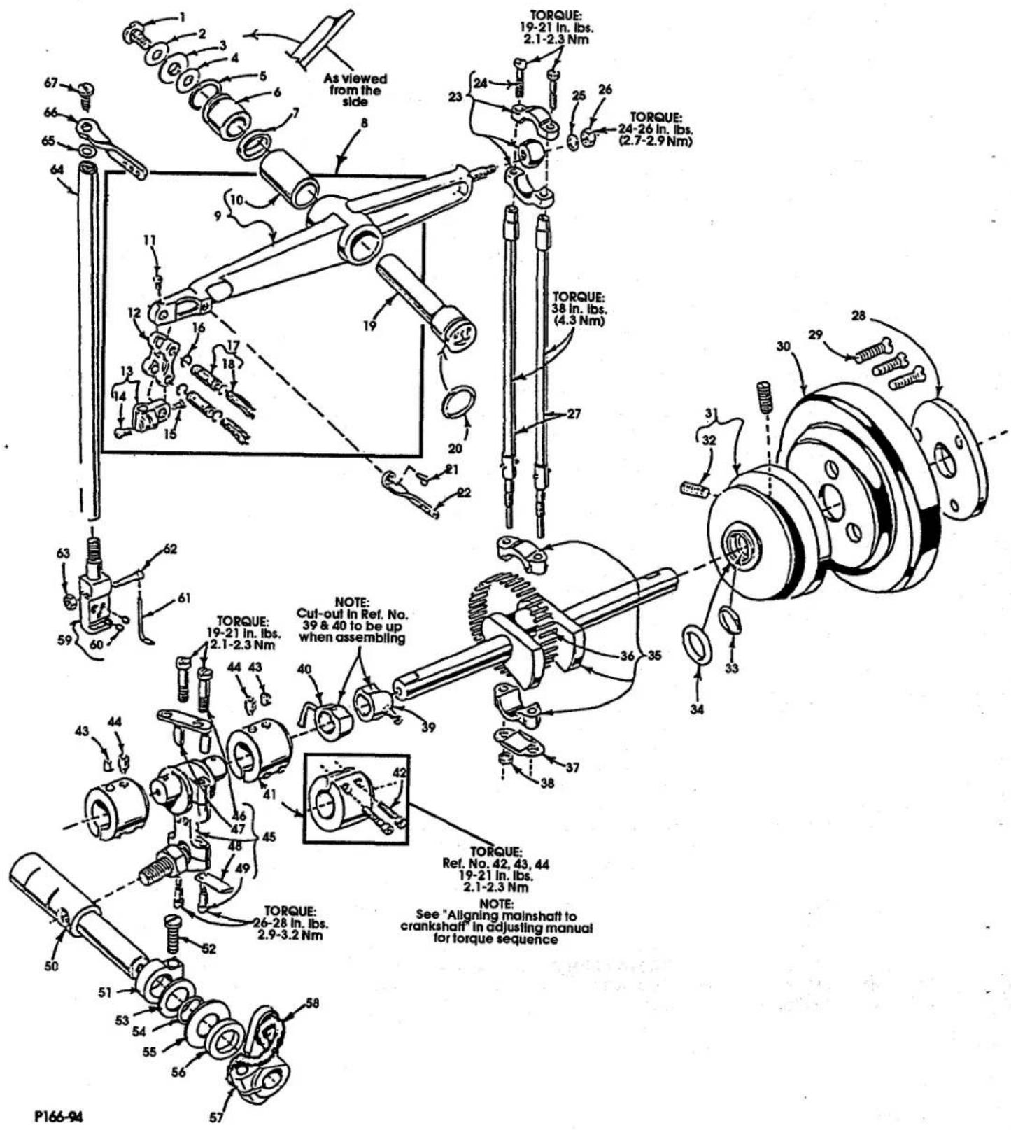
CRANKSHAFT, NEEDLE LEVER, NEEDLE BAR & LOOPER DRIVING PARTS (CONT.)
Ref.
No. Part No.
Description
Amt.
Req.
1. thru 49. See preceding page
-
52942AF Looper Drive Lever Rocker Shaft 1
-
34342J Clamp 1
-
22652A12 Screw 1
-
57849C Thrust Washer 1
-
660-202 "O"-ring 1
-
56390H Washer 1
-
52951C Thrust Washer 1
-
56342K Looper Drive Lever 1
-
CL-21 Oil Wick 1
-
57818A060 Needle Head, for all 3 needle, .060 gauge machines .... 1
-
28C Screw, needle head 3
-
34818B Cover Thread Guide 1
-
99331A Screw, for cover thread guide .... 1
-
95262V Nut, for screw 1
-
34317 Needle Bar 1
-
27-435BLK Washer, for needle bar thread 1
-
56958A Needle Bar Thread Eyelet 1
-
22768 Screw, for needle bar eyelet .... 1
P167-94
SPREADER & SPREADER DRIVE
| Ref. | Amt. | ||
| No. | Part No. | Description | Req. |
-
50345L Spreader .... 1
-
C50046 Spreader Holder 1
-
22562B Screw 2
-
77 Screw ....1
-
41332J Thrust Washer ....1
-
34847A Spreader Holder Drive Shaft ....1
-
1204002 Oil Wick 1
-
34848 Carrier Connecting Rod Assembly 4
-
22729 Screw
-
57835M Washer, ball 4
-
22729 Screw 1
-
93 Screw 1
-
20 Washer, for carrier connecting rod assembly ....1
-
18 Nut, for carrier connecting rod assembly .... 1
-
57849A Spreader Rocker Shaft Arm ....1
-
55235D Locking Stud 1
-
6042A Washer 1
-
55235E Nut 3
-
57849C Washer, for spreader rocker shaft collar 2
-
999-232 "O"-ring, for spreader rocker shaft ....1
-
52849 Spreader Rocker Shaft 2
-
57847 Crankshaft Thrust Collar 2
-
95 Screw 1
-
57849D Spreader Rocker Shaft Collar, inner ....1
-
55235E Nut 1
-
6042A Washer 1
-
55235D Locking Stud 2
-
22559G Screw, for spreader connecting rod ball joint, upper 2
- 22569G Screw, for ball joint ....1
-
29105BD Spreader Connecting Rod Ball Joint, upper 1
-
52952D Segment Lever 1
-
55235D Locking Stud ....1
-
6042A Washer 1
-
55235E Nut 1
-
18 Nut, for spreader connecting rod ball joint .... 1
-
HA20A Washer 2
-
52916 Connecting Rod .... 1
-
29126CR Spreader Drive Eccentric Assembly 2
-
95 Screw 1
-
52951-B Retaining Washer 1
-
660-246 Retaining Ring ....1
-
52951C Spacer Washer ....1
-
52947A Counterweight 2
-
22587H Screw, for counterweight ....
P071-93
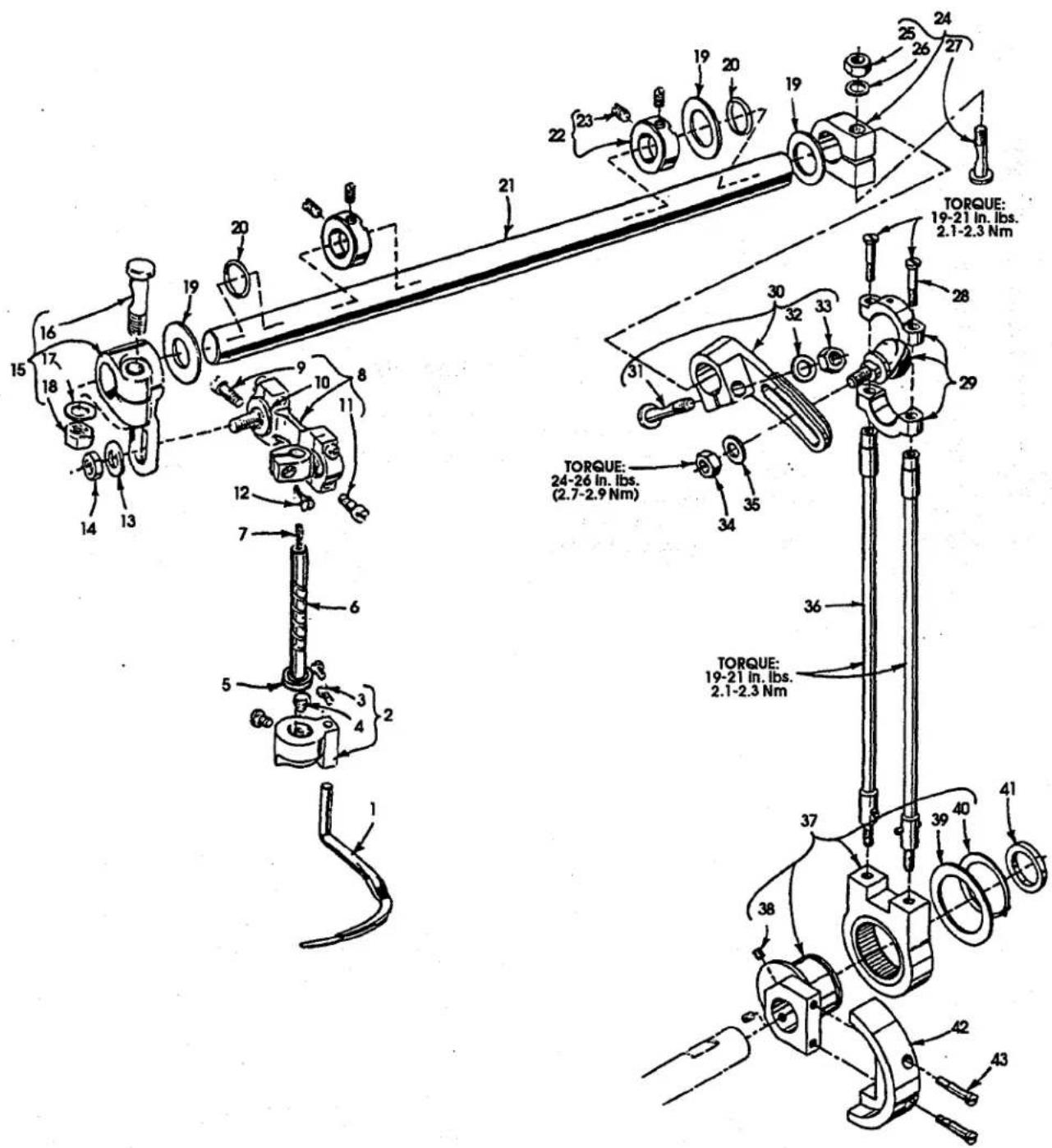
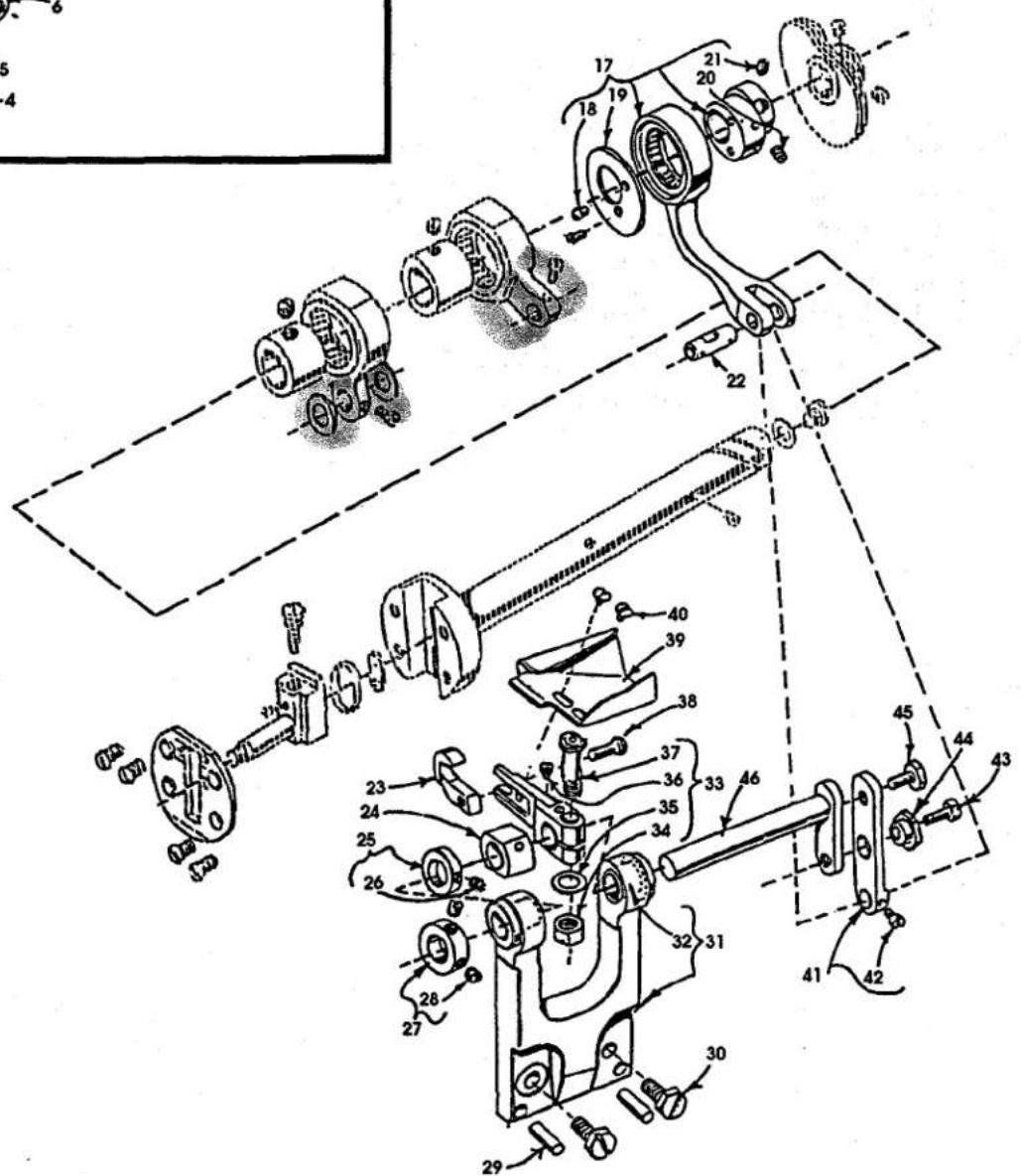
LOOPER ROCKER & CONNECTING ROD PARTS
| Ref. No. | Part No. | Description | Amt. Req. |
| 1. | 52825D | Holder, for front needle guard | 1 |
| 2. | 77 | Screw | 2 |
| 3. | 33174B | Screw | 2 |
| 4. | 51244L | Thrust Washer, for looper rocker shaft | 2 |
| 5. | 57725B | Front Needle Guard | 1 |
| 6. | 57846B | Nut, for looper rocker assembly | 1 |
| 7. | 57744A | Looper Rocker Frame 96 | 1 |
| 8. | 98 | Set Screw | 1 |
| 9. | 719 | Stop Screw | 1 |
| 10. | 51236J | Connecting Pin | 1 |
| 11. | 56344D | Looper Rocker Arm | 1 |
| 12. | CO67E | Cork Plug, for looper rocker shaft | 1 |
| 13. | 57744 | Looper Rocker Shaft | 1 |
| 14. | WO-3 | Wool Yam, for looper rocker shaft | 1 |
| 15. | 55244G | Stud, for looper rocker shaft collar | 1 |
| 16. | 51244N | Looper Rocker Shaft Collar | 1 |
| 17. | 51216N | Washer, for shaft stud | 1 |
| 18. | 18 | Nut, for shaft stud | 1 |
| 19. | 627 | Hexagon Screw | 1 |
| 20. | 20 | Washer, for looper lever stud screw | 1 |
| 21. | 56342K | Looper Drive Lever | 1 |
| 22. | 22882C | Screw | 1 |
| 23. | 20 | Washer | 1 |
| 24. | 29476LV | Looper Connecting Rod Ball Joint, right | 1 |
| 25. | 18 | Nut | 1 |
| 26. | 39141 | Looper Connecting Rod | 1 |
| 27. | 269 | Nut, for connecting rod | 2 |
| 28. | 87U | Screw, for ball joint oiler | 1 |
| 29. | 56393J | Ball Joint Oiler | 1 |
| 30. | 29192Z | Looper Rocker Assembly | 1 |
| 31. | 51745 | Stud, for looper rocker cone | 1 |
| 32. | 57713 | Looper Rocker | 1 |
| 33. | 15465F | Looper Rocker Cone | 1 |
| 34. | 88 | Screw | 2 |
| 35. | 258 | Lock Nut | 1 |
| 36. | 22829 | Screw | 1 |
| 37. | 96 | Spot Screw, for looper rocker frame | 1 |
| 38. | 22874 | Lock Screw, for looper rocker frame | 1 |
| 39. | 18 | Nut, for looper connecting rod ball joint, left | 1 |
| 40. | 52708B | Looper | 1 |
| 41. | 73 | Screw, for looper | 1 |
| 42. | 29105BA | Looper Connecting Rod Ball Joint, left | 1 |
| 43. | 22729C | Screw, for ball joint | 2 |
MAIN & DIFFERENTIAL FEED MECHANISMS
| Ref. | Ami. | ||
| No. | Part No. | Description | Req. |
-
57835R Feed Rocker Arm 1
-
55235D Stud, locking 1
-
6042A Washer 1
-
55235 Nut 1
-
22768A Screw 1
-
660-438 Retaining Ring 1
-
41391 Washer 2
-
75 Screw, for segment plate 2
-
52834N Nut, for differential feed regulating stud .... 1
-
39236C Regulating Stud Stop .... 1
-
51225W Washer, for regulating stud .... 1
-
22516 Screw, for segment plate .... 1
-
52836Y Feed Rocker Segment Plate 1
-
52836AA Shim, for segment plate 1
-
56335L Feed Rocker Shaft 1
-
52836AB Feed Rocker 1
-
22894P Screw, for feed rocker 2
-
57835X Shaft, for feed rocker, upper 1
-
56335D Collar, for feed rocker shaft 2
-
98 Screw, for collar 2
-
22593A Screw, for feed dog 2
-
Main Feed Dog 1
-
22653B10 Screw, for feed dog holder .... 1
-
51235G Washer 1
-
52853 Feed Dog Holder, main 1
-
22593 Screw, for guide 2
-
22635E24 Screw 1
-
57837D Guide Plate, for differential feed dog .... 1
-
57853E Guide Plate and Support 1
-
57825G Rear Needle Guard 1
-
91D Screw, for rear needle guard .... 1
-
57834A Differential Feed Bar 1
-
CL-21 Oil Wick 1
-
Differential Feed Dog 1
-
91 Screw, for differential feed dog .... 1
-
52834P Main Feed Bar 1
-
22637P-24 Screw 1
-
39237G Bushing, for differential feed bar 2
-
22560B Screw 1
-
77 Screw, for main feed bar 1
-
39237 Guide, for differential feed bar 1
-
22565C Screw 2
-
907 Nut, for regulating stud .... 1
-
51225W Washer, for regulating stud 3
-
39236V Bushing, for differential feed drive link 1
-
52835T Driving Link 1
-
CL-21 Oil Wick 1
-
39236B Regulating Stud, for differential feed 1
-
29476RJ072 Feed Lift Eccentric Assembly 1
-
22894AA Screw 1
-
thru 73. See following page
MAIN & DIFFERENTIAL FEED MECHANISMS (CONT.)
Ref.
No. Part No.
Description
Amt.
Req.
1. thru 50. See preceding page
- 29476RS062 Looper Avoid Eccentric Assembly 1
- 22894AA Screw 1
- 52923D Looper Thread Take-Up 1
- 22580D Screw, for take-up 2
- WO-3 Wool Yarn 2
- 51236J Link Pin 2
- 57722B Main Shaft 1
- 56322B Screw 1
- 22891B Gasket 1
- 22801 Screw, for main shaft 1
- 56336D Insert, feed crank stud .... 1
- 660-269B Quad Ring 1
- 22543B Screw, for stitch regulating 1
- 56336 Feed Crank Stud 1
- 22798C Screw, for feed crank stud .... 1
- 56322C Head Plate 1
- 22525A Screw, for head plate 4
- 56336K Feed Crank Link Assembly 1
- 56336C Ferrule 1
- 51236J Link Pin 1
- 666-149 1/8" Felt Wick 1
- 269 Nut, for feed crank stud .... 1
- 21657E Washer, for feed crank stud .... 1
P073-93
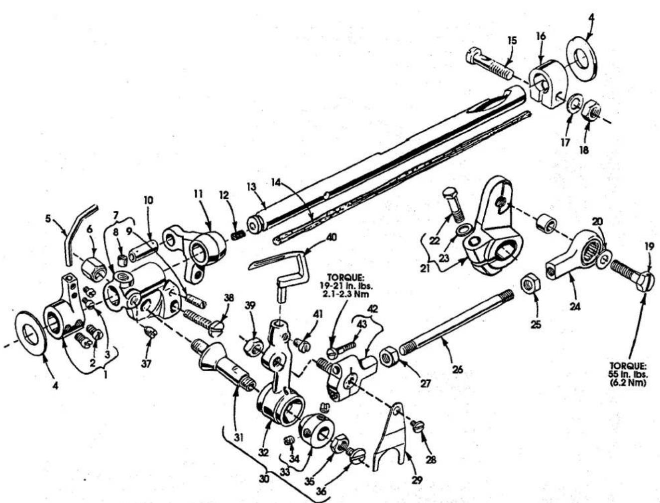
MAIN SHAFT & KNIFE DRIVING PARTS
| Ref. | Amt. | ||
| No. | Part No. | Description | Req. |
-
57795 Lock Nut 1
-
22771A Adjusting Screw 1
-
57750D Knife Bracket Lower 1
-
667C-8 Dowel Pin 2
-
22653B-8 Screw 2
-
14077 Nut 1
-
89 Screw 1
-
57740 Spring 1
-
57750E Guide Shaft 1
-
98 Screw 1
-
57750C Knife Block Lower 1
-
57950B Knife Clamp Lower 1
-
22588A Screw 1
-
57949 Knife Lower 1
-
88B Screw 2
-
57750H Knife Block Pin Lower 1
-
29132AJ Knife Drive Eccentric Assembly, .276" (7.01 mm) throw .... 1
-
22KH Screw 2
-
57751 Eccentric Retaining Plate 1
-
22560 Set Screw 2
-
88 Screw 2
-
51236J Link Pin 1
-
57770A Knife Upper 1
-
57750G Knife Bearing Block Lower 1
-
57735 Stop Collar 1
-
22565C Screw 1
-
39147D Collar 1
-
88 Screw 2
-
667C-10 Dowel Pin 2
-
22852A Screw 2
-
57773B Knife Bracket 1
-
57773 Bushing 2
-
57773A Knife Drive Lever 1
-
55235E Nut 1
-
6042A Washer 1
-
22764 Spot Screw 1
-
57736A Locking Stud 1
-
79048 Screw 1
-
57779A Chip Guard, upper 1
-
87U Screw 2
-
57750F Knife Drive Link 1
-
77 Screw 1
-
22782A Screw 1
-
57750B Eccentric Nut 1
-
22567B Screw 1
-
57785 Knife Drive Shaft 1
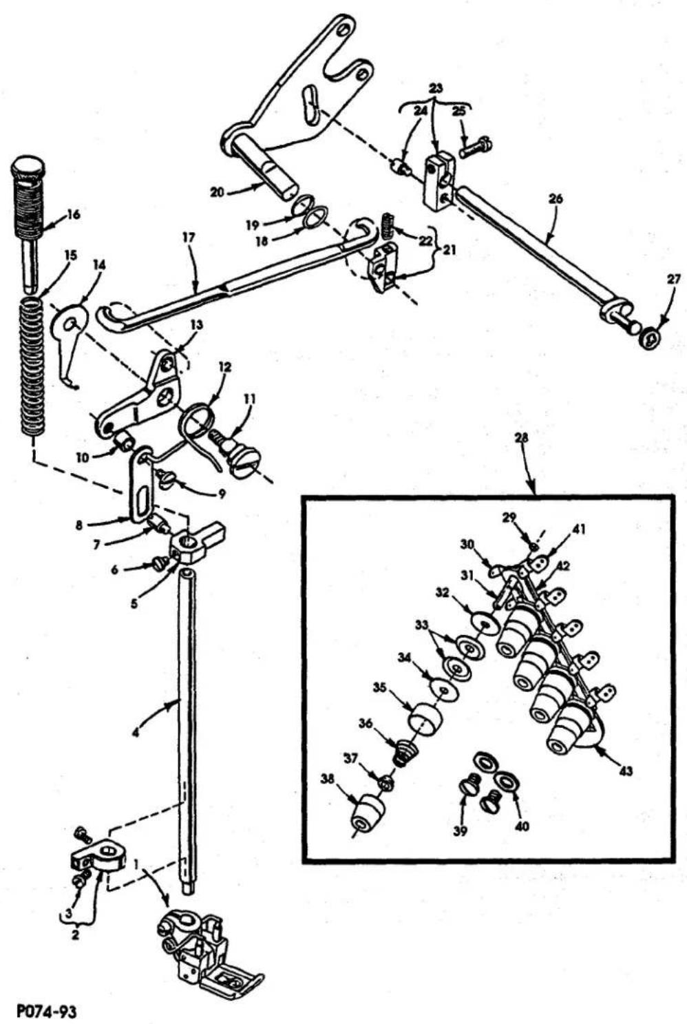
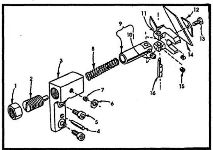
THREAD TENSION & LIFTER LEVER PARTS
| Ref. | Amt. | ||
| No. | Part No. | Description | Req. |
-
---- Presser Foot .... 1
-
523306AW Collar, for presser bar stop ....1
-
22786B Screw, for collar 2
-
51257K Presser Bar ....1
-
51257M Presser Bar Guide ....1
-
22596F Screw
-
22892E Screw, for presser bar guide ....1
-
34883 Lifter Lever Link ....1
-
99392A Screw, for lever link ....1
-
57883 Spacer Bushing .... 1
-
22557G Screw 1
-
56383D Spring, for lifter rod .... 1
-
34383BA Lifter Lever 1
-
57893B Head Oil Tube Clamp .... 1
-
51256C Presser Bar Spring .... 1
-
56356A Regulator Spring, for presser spring .... 1
-
56383AB Connecting Rod 1
-
39552C Washer, for lifter lever .... 1
-
660-207 "O"-ring, for lifter lever 1
-
51283H Lifter Lever 1
-
53783N Lifter Lever, right 1
-
22537 Screw 1
-
21657Y Lifter Lever Connection, tension release .... 1
-
402 Screw, for guide ....1
-
22596 Screw 1
-
21657W Lifter Lever Shaft .... 1
-
660-283A Retainer Washer ....1
-
29477NF Tension Assembly 1
-
U94187F Nut (11/64-40) 5
-
U94192K Thread Tension Eyelet 5
-
U94192P Tension Post 5
-
U94192E Felt Tension Disc 5
-
U94192D Tension Disc 10
-
U94192N Felt Tension Disc 5
-
U94192M Shield, for spring 5
-
U94192W Spring, for spreader (blue) 1
- U94192T Spring, for needle (red) 3
- U94192L Spring, for looper (blue) 1
-
39592AK Ferrule, for tension spring 5
-
U94192S Knob, needle (red) 3
- U94192V Knob, for spreader (blue) 1
- U94192J Knob, for looper (yellow) 1
-
22839C Screw 2
-
80557 Washer 2
-
57865 Thread Guide, lead-in .... 5
-
21657AP Separator, for tension disc .... 1
-
57892L Support, for tension post .... 1
P170-94
COVERS & MISCELLANEOUS PARTS
| Ref. | Amt. | ||
| No. | Part No. | Description | Req. |
-
52882AL End Cover .... 1
-
660-1001 Rubber Grommet 4
-
87A Screw 1
-
22773A Screw 3
-
60038K Washer 3
-
80 Screw, for cloth plate 2
-
52801M Cloth Plate .... 1
-
22839C Screw, for cloth plate .... 1
-
52802F Cloth Plate Slide Cover.... 2
Screw, for panel 1
-
22585A Screw 3
-
22524 Screw 8
-
56382G Oil Resistant Top Cover....1
-
56382H Gasket 1
-
57894E Oil Shield 1
-
87 Screw, for throat plate .... 1
-
57885D Hinge Bracket, right 2
-
52882AP Swing Down Cover .... 1
-
57885C Hinge Bracket, left .... 1
-
22848 Screw, for hinge 8
-
43281K Spring, for hinge bracket 2
-
90 Screw 4
-
660-1008 Rubber Grommet 2
-
52880C Throat Plate Support .... 1
Pin 2
-
22839 Screw, for throat plate support 3
-
---- Throat Plate .... 1
-
57885 Hinge Bracket 1
-
57885B Hinge Bracket 1
P171-94
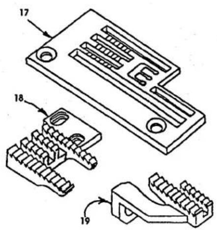
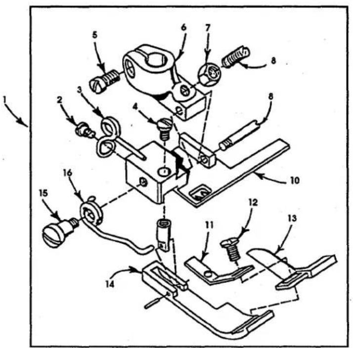
PRESSER FOOT, THROAT PLATE & FEED DOG PARTS
| Ref. | Amt. | ||
| No. | Part No. | Description | Req. |
-
52720M16 Presser Foot Assembly 1
-
605 Screw 1
-
52730AB Spring 1
-
73A Screw 1
-
91 Screw, for shank .... 1
-
52730T Shank 1
-
51430F Nut 1
-
22840A Screw 1
-
22799B Screw, for hinge 1
-
52730AC-16 Bottom, for presser foot assembly 1
-
52730AE Tape Guide 1
-
605A Screw 1
-
52730AD Chip Guard 1
-
52730AF Yielding Section 1
-
57WD Screw 1
-
52730Y Spring 1
-
C52724M16 Throat Plate 1
-
52705M Main Feed Dog 1
-
52726C Differential Feed Dog 1
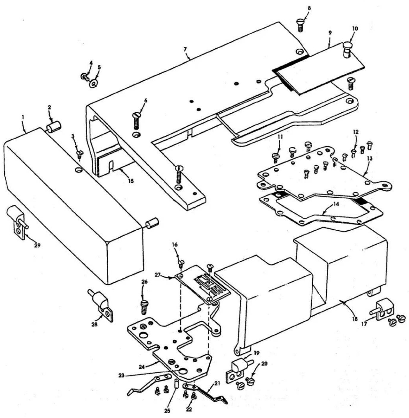
STEPPER MOTOR METERING DEVICE & SYNCHRONIZER KIT
| Ref. | Amt. | ||
| No. | Part No. | Description | Req. |
-
57882M Head Cover, for upper stepper motor .... 1
-
88D Screw 1
-
23306AP Head Cover Elastic Guide Bracket 1
-
23306AV Elastic Stop Guide 2
-
25B Screw 2
-
23306BL Mounting Block 1
-
23306AW Elastic Guide Bracket 1
-
22768B Screw 2
-
23306AU Elastic Guide 1
-
23306AV Elastic Stop Guide 2
-
25B Screw 2
-
670H139 Stepper Motor Metering Device 1
-
22653B36 Mounting Screw 2
-
95166C Screw 2
-
57849G Connector Bracket 1
- 35086LXD Plate 1
-
90241G Motor Wire Connection .... 1
-
90233MBA Clamp 1
-
95167DV Screw M3 x 40 3
-
997YX-455 Motor and Cable Assembly 1
-
95166V Screw M3 X 8 4
-
35086WD Mounting Plate 1
-
22737 Screw 7
-
95956 Washer 5
-
99697FC Flat Spring 2
-
34386AB1 Stand Off 1
-
34386B Elastic Guide 2
-
998-382 Knob 1
-
25B Screw 2
-
34386KC Cover 1
-
34386KB Cover 1
- 999-106XA Bearing 1
- 99316 Screw 3
-
77A Screw 2
-
34386CB Roller Bracket .... 1
-
34386GD Roller 1
-
34386AC Knife Holder 1
-
34386AB2 Stand Off 2
-
34386EH Roller 1
-
22743 Set Screw 2
-
35086WD1 Bushing 1
-
670N4 Control Box 1
-
AS12-13 Mounting Bracket 1
-
670M10 Synchronizer 1
-
670N5 Driver Box 1
natural_image
Technical line drawing of a mechanical assembly with multiple components and rods (no text or symbols)
P172-94
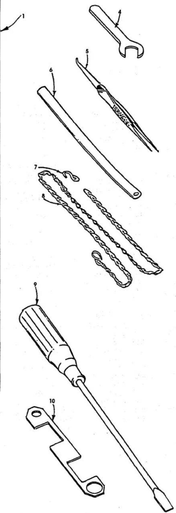
THREAD STAND & MISCELLANEOUS ACCESSORIES
Ref.
No. Part No.
Description
Amt.
Req.
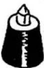
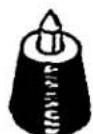
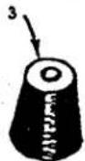
- 21101W5 Thread Stand.... 1
- 51295B Isolator 3
- 51295A Isolator 1
- 21388 Wrench....1
- 660-240 Thread Tweezer 1
- 23279D Threader....1
- 660-264 "S" Hook 1
- 421D34 Chain 2
- G21201 Screw Driver 1
- TT35 Looper Gauge (sold separately) 1
- 660-457 Plastic Cover (not shown) .... 1
- 28604R Oil Can (not shown) 1
- 660-662A Bundling Strap (not shown) 3
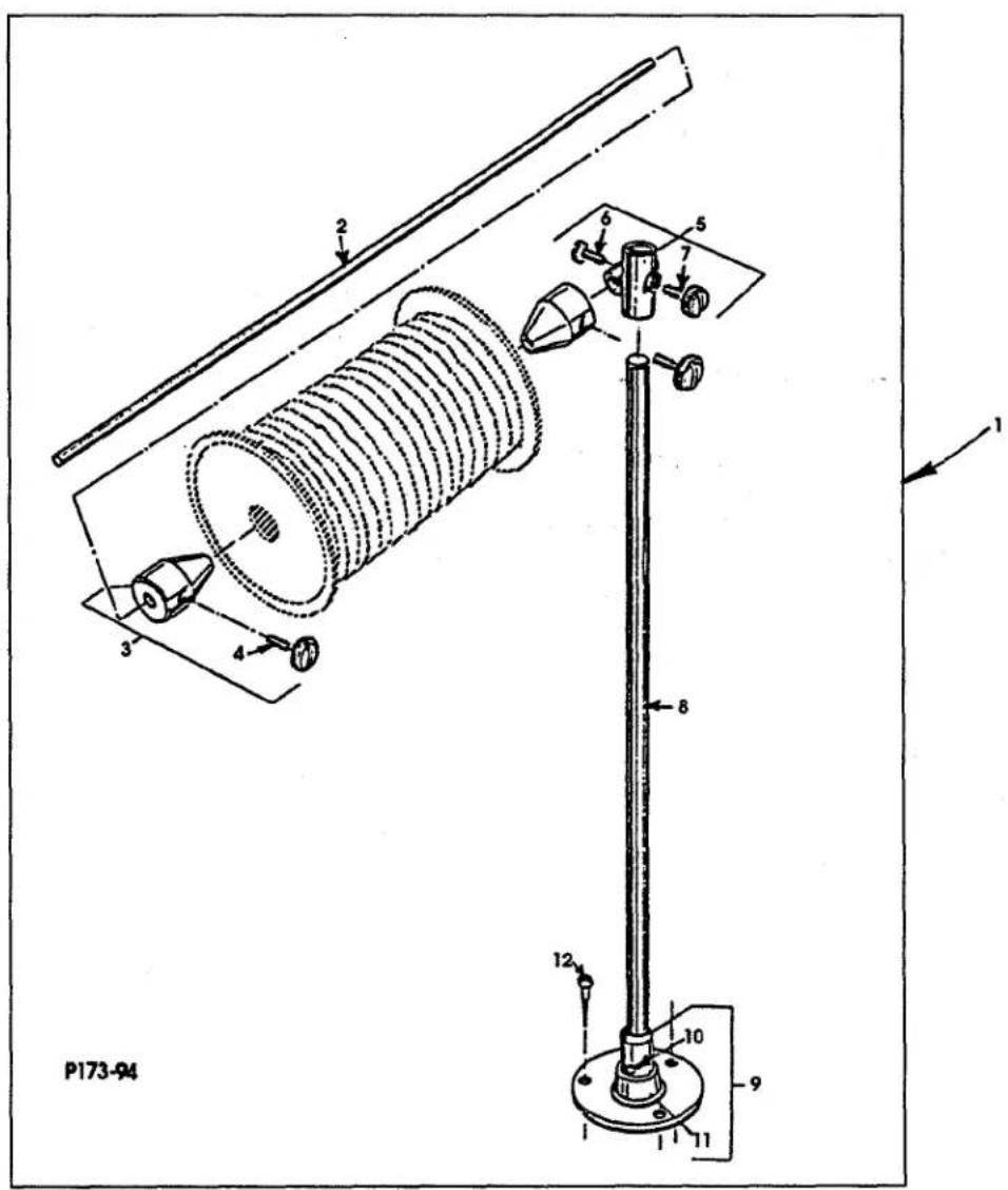
TAPE REEL ASSEMBLIES
| Ref. No. | Part No. | Description | Amt. Req. |
| 1. | 90561K | Tape Reel Assembly | 1 |
| 2. | 29480AHW | Tape Reel Rod | 1 |
| 3. | 21102B | Cone | 2 |
| 4. | 93064H-1 | Thumb Screw | 2 |
| 5. | 201C | Rod Support | 1 |
| 6. | G21217A | Thumb Screw | 1 |
| 7. | 188D | Thumb Screw | 1 |
| 8. | 22728 | Rod | 1 |
| 9. | 21104B-18 | Base | 1 |
| 10. | 21114AU | Set Screw | 1 |
| 11. | 22651CD-4 | "O"-ring | 1 |
| 12. | 660-304 | Wood Screw | 3 |
NOTES
NOTES
NUMERICAL INDEX OF PARTS
| 1204002 19 | 22593A 23 | 269 21, 25 | 50373CQ 11 | 52882AJ 38 |
| 12934A 15 | 22596 29 | 27-435BLK 17 | 51-902BLK 13 | 52882AK 31 |
| 14077 27 | 22596F 29 | 28604R 37 | 51054 25 | 52882AL 31 |
| 15465F 21 | 22635E24 23 | 28C 17 | 51154E 13 | 52882AP 31 |
| 158B 9 | 22637P-24 23 | 29105BA 21 | 51216M 15 | 52882M 35 |
| 18 19, 21 | 22651CD-4 38 | 29105BB 15 | 51216N 15, 21 | 52883R 13 |
| 188D 38 | 22652A12 17 | 29105BC 15 | 51216P 15 | 52888B 29 |
| 20 9, 19, 21 | 22653B-8 27 | 29105BD 19 | 51225W 23 | 52904B 9 |
| 201C 38 | 22653B10 23 | 29126CR 19 | 51235G 23 | 52904E 9 |
| 21101W4 37 | 22653B36 35 | 29132AJ 27 | 51236J 21, 25, 27 | 52904G 9 |
| 21101W5 37 | 22653L-8 15 | 29192Z 21 | 51244L 21 | 52916 19 |
| 21102B 38 | 22711 13 | 29348AF 15 | 51244N 21 | 52923D 25 |
| 21104B-18 38 | 22728 38 | 29476LV 21 | 51247 19 | 52942AA 17 |
| 21114AU 38 | 22729 19 | 29476NZ 15 | 51250D 15 | 52942AB 13 |
| 21201 37 | 22729AB 15 | 29476RJ062 25 | 51250V 15 | 52942AC 13 |
| 21375CE 9 | 22729C 21 | 29476RJ072 23 | 51254K 15 | 52942AF 17 |
| 21388 37 | 22737 35 | 29477NF 29 | 51256C 29 | 52947A 19 |
| 21388BA 37 | 22743 35 | 29477NG 29 | 51257AA 13 | 52951-B 19 |
| 21657AP 29 | 22764 27 | 29480AHW 38 | 51257K 29 | 52951C 17, 19 |
| 21657E 25 | 22768 9, 15, 17 | 33174B 21 | 51257M 29 | 52952D 19 |
| 21657W 29 | 22768A 23 | 33795 11 | 51283H 29 | 52958D 9 |
| 21657X 13 | 22768B 35 | 33795C 11 | 51295A 37 | 53-28-106-24 31 |
| 21657Y 29 | 22771A 27 | 34317 17 | 51295B 37 | 53634C 38 |
| 22516 9, 23 | 22773A 31 | 34342J 17 | 51430F 33 | 53758 9 |
| 22519C 23 | 22782A 27 | 34383BA 29 | 51745 21 | 53783N 29 |
| 22524 9, 31 | 22786B 29 | 34386AB1 35 | 523306AW 29 | 54458-9 15 |
| 22525A 25 | 22798C 25 | 34386AB2 35 | 52336A 15 | 55235 23 |
| 22537 29 | 22799B 33 | 34386AC 35 | 52705M 33 | 55235D 19, 23 |
| 22539 13 | 22801 25 | 34386B 35 | 52708B 21 | 55235E 19, 27 |
| 22539AA 11 | 22829 9, 21 | 34386CB 35 | 52720M12 33 | 55244G 21 |
| 22539AB 11 | 22839 31 | 34386EH 35 | 52720M16 33 | 56190 13 |
| 22539R 13 | 22839C 9, 29, 31 | 34386GD 35 | 52726C 33 | 56315A 15 |
| 22539S 9 | 22840A 33 | 34386KC 35 | 52730AB 33 | 56316 15 |
| 22541C 9, 11 | 22848 9, 11, 31 | 34758 11 | 52730AC-12 33 | 56316C 15 |
| 22542 11 | 22851D 11 | 34818B 17 | 52730AC-16 33 | 56321S 15 |
| 22543B 25 | 22852A 27 | 34831C 11 | 52730AD 33 | 56322B 25 |
| 22548 9 | 22852G 38 | 34847A 19 | 52730AE 33 | 56322C 25 |
| 22557G 29 | 22874 21 | 34848 19 | 52730AF 33 | 56335D 23 |
| 22559G 15, 19 | 22882C 21 | 34883 29 | 52730T 33 | 56335L 23 |
| 22560 27 | 22889H 9 | 35086LXD 35 | 52730Y 33 | 56336 25 |
| 22560B 23 | 22891B 25 | 35086WD 35 | 52801M 31 | 56336B 25 |
| 22562 29 | 22892E 29 | 35086WD1 35 | 52802F 31 | 56336C 25 |
| 22562A 15 | 22894AA 25 | 35086X 35 | 52804E 9 | 56336D 25 |
| 22562B 19 | 22894AB 15 | 35897BV 13 | 52825D 21 | 56336K 25 |
| 22564 15, 31 | 22894C 15 | 39141 21 | 52834N 23 | 56342D 13 |
| 22564B 11 | 22894D 15 | 39147D 27 | 52834P 23 | 56342K 17, 21 |
| 22565C 23, 27 | 22894E 11 | 39236B 23 | 52834R 23 | 56343C 15 |
| 22567B 27 | 22894P 23 | 39236C 23 | 52835T 23 | 56343E 15 |
| 22569B 13 | 22KH 27 | 39236V 23 | 52836AA 23 | 56343F 15 |
| 22569C 9 | 23279D 37 | 39237 23 | 52836AB 23 | 56344D 21 |
| 22569G 19 | 23306AP 35 | 39237G 23 | 52836W 23 | 56350D 15 |
| 22569J 11 | 23306AU 35 | 39552C 29 | 52836Y 23 | 56350E 15 |
| 22574 15 | 23306AV 35 | 39592AK 29 | 52849 19 | 56350F 15 |
| 22580D 25 | 23306AW 35 | 402 29 | 52853 23 | 56350G 15 |
| 22585A 9, 11, 13, 31 | 23306BL 35 | 41391 23 | 52853B 23 | 56350J 15 |
| 22585C 9 | 23432B 38 | 421D34 37 | 52864Y 31 | 56350K 15 |
| 22586R 15 | 23439G 13 | 43281K 31 | 52879A 13 | 56354D 15 |
| 22587K 15 | 258 21 | 50-216BLK 9 | 52880A 31 | 56356A 29 |
| 22588A 27 | 258A 13 | 50-895BLK 13 | 52880C 31 | 56382AA 9 |
| 22593 23 | 25B 35 | 50345L 19 | 52882AG 38 | 56382AB 9 |
NUMERICAL INDEX OF PARTS
| 56382AC 9 | 57835X 23 | 660-207 29 | 95956 35 |
| 56382AK 15 | 57836B 13 | 660-215 15 | 96 21 |
| 56382C 9 | 57837D 23 | 660-230 13 | 98 21, 23, 27 |
| 56382D 9 | 57842B 13 | 660-240 37 | 98A 9 |
| 56382E 9 | 57844 11 | 660-246 19 | 99316 35 |
| 56382G 31 | 57844A 11 | 660-264 37 | 99331A 17 |
| 56382H 31 | 57844C 9 | 660-269B 25 | 99392A 29 |
| 56382J 9 | 57846B 21 | 660-283A 29 | 99682XCA 11 |
| 56382K 9 | 57847 19 | 660-304 38 | 99697FC 35 |
| 56382L 9 | 57847B 13 | 660-406 13 | 997YX-455 35 |
| 56382Y 9 | 57849 13 | 660-438 23 | 997YY-455 35 |
| 56383AB 29 | 57849A 19 | 660-457 37 | 998-382 35 |
| 56383D 29 | 57849C 17, 19 | 660-617 11 | 999-106XA 35 |
| 56390 13 | 57849D 9, 19 | 660-625 15 | 999-232 19 |
| 56390E 13 | 57849G 35 | 660-662A 37 | AS12-13 35 |
| 56390G 13 | 57852A 19 | 660-665 13 | C50046 19 |
| 56390H 13, 17 | 57853E 23 | 660-738 38 | C52724M16 33 |
| 56390J 13 | 57854 13 | 660-739 13 | C52724N12 33 |
| 56392F 29 | 57858 9 | 660-870 37 | CL-21 13, 17, 23 |
| 56393J 21 | 57858A 11 | 666-149 25 | CO67E 21 |
| 56393P 13 | 57858B 9 | 666-214 13 | G21201 37 |
| 56393Q 13 | 57865 29 | 666-259 13 | G21217A 38 |
| 56393W 13 | 57882J 9 | 667C-10 27 | G50-785 19 |
| 56958A 15, 17 | 57882K 11 | 667C-8 27 | HA20A 19 |
| 57705A 33 | 57882L 11 | 670H139 35 | RM2871B 37 |
| 57713 21 | 57882M 11, 35 | 670M10 35 | T38 38 |
| 57722B 25 | 57883 29 | 670N4 35 | TT35 37 |
| 57725B 21 | 57885 31 | 670N5 35 | U94187F 29 |
| 57735 27 | 57885B 31 | 69H 9 | U94192D 29 |
| 57736A 27 | 57885C 31 | 719 21 | U94192E 29 |
| 57740 27 | 57885D 31 | 73 21 | U94192J 29 |
| 57744 21 | 57890B 13 | 73A 9 | U94192K 29 |
| 57744A 21 | 57892C5 11 | 75 23 | U94192L 29 |
| 57750B 27 | 57892H 11 | 77 15, 19, 21, 23, 27 | U94192M 29 |
| 57750C 27 | 57892J 11 | 77A 35 | U94192N 29 |
| 57750D 27 | 57892L 29 | 79048 27 | U94192P 29 |
| 57750E 27 | 57893 13, 15 | 80 31 | U94192S 29 |
| 57750F 27 | 57893A 13 | 80557 29 | U94192T 29 |
| 57750G 27 | 57893B 29 | 80665F 11 | U94192V 29 |
| 57750H 27 | 57893C 13 | 87 31 | U94192W 29 |
| 57751 27 | 57894 13 | 87A 31 | WO-3 15, 21, 25 |
| 57757B 9 | 57894D 9 | 87U 9, 21, 27 | |
| 57770 11 | 57894E 31 | 88 21, 27 | |
| 57770A 27 | 57944B 11 | 88B 27 | |
| 57773 27 | 57949 27 | 88D 35 | |
| 57773A 27 | 57950B 27 | 89 23, 27 | |
| 57773B 27 | 57WD 33 | 90 9, 13, 31 | |
| 57779A 27 | 59493A 13, 15 | 90233MBA 35 | |
| 57782M 9 | 6-67-125 13 | 90241G 35 | |
| 57785 27 | 60038K 31 | 90651K 38 | |
| 57795 27 | 6042A 19, 23, 27 | 907 23 | |
| 57795B 9 | 605 33 | 91 23, 33 | |
| 57818A060 17 | 605A 11, 33 | 91D 23 | |
| 57821D 15 | 61321L 15 | 93 19 | |
| 57822A 25 | 627 21 | 93064H-1 38 | |
| 57825G 23 | 660-1001 31 | 95 9, 19 | |
| 57834A 23 | 660-1002 9 | 95166C 35 | |
| 57834J 23 | 660-1008 31 | 95166V 35 | |
| 57835M 19 | 660-202 15, 17 | 95167DV 35 | |
| 57835R 23 | 660-206 15 | 95262V 17 |
NOTES

natural_image
World map with latitude and longitude grid lines, showing continents and oceans (no text labels)WORLDWIDE SALES AND SERVICE
Union Special Corporation maintains sales and service facilities throughout the world. These offices will aid you in the selection of the right sewing equipment for your particular operation. Union Special Corporation representatives and service technicians are factory trained and are able to serve your needs promptly and efficiently. Whatever your location, there is a qualified representative to serve you.
It is important to remember that LEWIS® machines are also products of Union Special Corporation, thus offering the Finest Quality sewing machines.
Corporate Offices:
One Union Special Plaza
Huntley, IL 60142
(708) 669-5101
Brussels, Belgium
Commerce, CA
Leicester, England
Miami, FL
Paris, France
Norcross, GA
Möglingen, Germany
Huntley, IL
Milan, Italy
Osaka, Japan
Hong Kong
Charlotte, N.C.
Warminster, PA
Montreal, Quebec
El Paso, TX
Mission, TX
Other Representatives throughout all parts of the world.

Finest Quality
Union Special® INDUSTRIAL SEWING EQUIPMENT
INDUSTRIAL SEWING EQUIPMENT
- Union Special INDUSTRIAL SEWING EQUIPMENT
- PREFACE
- SAFETY RULES
- General Operating Directions
- Special Operating Directions
- General Maintenance Directions
- Special Maintenance Directions
- Standards
- CONTENTS
- IDENTIFICATION OF MACHINES
- MACHINE STYLES
- ILLUSTRATIONS
- IDENTIFYING PARTS
- NEEDLES
- TYPE
- DESCRIPTION
- TERMS
- MAIN FRAME, CAST-OFF PLATE & MISCELLANEOUS COVERS
- MAIN FRAME, CAST-OFF PLATE & MISCELLANEOUS COVERS (CONT.)
- MAIN FRAME, BUSHINGS, OIL SIGHT GAUGE & MISCELLANEOUS OILING PARTS
- CRANKSHAFT, NEEDLE LEVER, NEEDLE BAR & LOOPER DRIVING PARTS
- CRANKSHAFT, NEEDLE LEVER, NEEDLE BAR & LOOPER DRIVING PARTS (CONT.)
- thru 49. See preceding page
- SPREADER & SPREADER DRIVE
- LOOPER ROCKER & CONNECTING ROD PARTS
- MAIN & DIFFERENTIAL FEED MECHANISMS
- MAIN & DIFFERENTIAL FEED MECHANISMS (CONT.)
- thru 50. See preceding page
- MAIN SHAFT & KNIFE DRIVING PARTS
- THREAD TENSION & LIFTER LEVER PARTS
- COVERS & MISCELLANEOUS PARTS
- PRESSER FOOT, THROAT PLATE & FEED DOG PARTS
- STEPPER MOTOR METERING DEVICE & SYNCHRONIZER KIT
- THREAD STAND & MISCELLANEOUS ACCESSORIES
- NOTES
- WORLDWIDE SALES AND SERVICE
Mærke : Union Special
Model : FS133E270MBU060
Kategori : Symaskine