
35800DLW - Symaskine Union Special - Gratis brugsanvisning og manual
Find enhedens vejledning gratis 35800DLW Union Special i PDF-format.

Brugerspørgsmål om 35800DLW Union Special
0 spørgsmål om dette apparat. Besvar dem du kender, eller stil dit eget.
Stil et nyt spørgsmål om dette apparat
Download vejledningen til din Symaskine i PDF-format gratis! Find din vejledning 35800DLW - Union Special og tag din elektroniske enhed tilbage i hånden. På denne side er alle dokumenter nødvendige for brugen af din enhed offentliggjort. 35800DLW af mærket Union Special.
BRUGSANVISNING 35800DLW Union Special
Union Special® INDUSTRIAL SEWING EQUIPMENT
ILLUSTRATED PARTS LIST
MANUAL NO. PT9407
STYLES
35800DLW
35800DWW
35800DWWL
Sixth Edition Copyright 1994
By
Union Special Corporation Rights Reserved In All Countries
Printed in U.S.A. August 1994
PREFACE
This parts manual has been prepared to assist you in locating individual parts or assemblies on 35800 Series machines. It can be used in conjunction with Union Special Adjusting Manual IN9406.
It is the desire of Union Special that each machine run at its optimum performance. Parts listed in this manual are designed specifically for your machine and are manufactured with utmost precision to assure long lasting service.
This manual has been comprised on the basis of available information. Changes in design and/or improvements may incorporate a slight modification of configuration in illustrations or part numbers.
On the following pages are illustrations and terminology used in describing the parts used on 35800 Series machines.
SAFETY RULES

General Operating Directions
The sewing machines described in this instruction manual are prohibited from being put into service until it has been ascertained that the sewing units, in which these sewing machines will be built-in have conformed with the EC Council Directives (89/392/EEC, Annex II B).
- Before putting the machines described in this manual into service, carefully read the instructions. The starting of each machine is only permitted after taking notice of the instructions and by qualified operators.
IMPORTANT! Before putting the machine into service, also read the safety rules and instruction from the motor supplier.
-
Observe the national safety rules valid for your country.
-
Each machine is only allowed to be used as foreseen. The foreseen use of the particular machine is described in paragraph "STYLES OF MACHINES" of this instruction manual. Another use, going beyond the description, is not as foreseen.
-
All safety devices must be in position when the machine is ready for work or in operation. Operation of the machine without the appertaining safety devices is prohibited.
-
The following safety devices are components of the sewing machines: Sewing guard, needle lever eyelet guard, needle bar guard, needle break protection shield and handwheel-belt guard.
-
When gauge parts are exchanged (i.e. needle, presser foot, needle plate, feed dog and bobbin), during threading, when the operator leaves the workplace, during service work, the machine must be isolated form the mains by switching off the main switch or disconnecting the main plug. On mechanically operated clutch motors without a start inhibitor it is necessary to wait until the motor has stopped.
-
Wear safety glasses.
-
In case of machine conversions and changes all valid safety rules must be considered. Conversions and changes are made at your own risk.
-
Commissioning of the sewing head is prohibited until such time as the entire sewing unit is found to comply with EC regulations.
-
The warning hints in the instructions are marked with one of these two symbols:

Items require special attention
Danger of injury to operative or service staff
Be sure to observe and adhere to these indications and to the generally applicable regulations.
Special Operating Directions
- For the following the machine has to be disconnected from the power supply by turning off the main switch or by pulling out the mains plug:
11.1 For threading needle(s), looper, spreader etc.
11.2 For replacing sewing tools such as needle, presser foot, throat plate, looper, spreader, feed dog, needle guard, folder, fabric guide etc.
11.3 When leaving the workplace and when the workplace is unattended.
11.4 For maintenance work.
11.5 When using clutch motors without actuation lock, wait until the motor is stopped totally.
General Maintenance Directions
-
Maintenance, repair and conversion work (see item 8) must be done only by trained technicians or special skilled personnel under consideration of the instructions.
-
Any work on the electrical equipment must be done by an electrician or under direction and supervision of special skilled personnel.
Special Maintenance Directions
-
Work on parts and equipment under electrical tension is not permitted.
-
Before doing maintenance and repair work on the pneumatic equipment, the machine has to be disconnected from the compressed air supply. In case of existing residual air pressure after disconnecting from compressed air supply (e.g. pneumatic equipment with air tank), the pressure has to be removed by bleeding.
Exceptions are only allowed for adjusting work and function checks done by special skilled personnel.
Standards
- The sewing machines described in this manual are built according to the following standards:
EN292-2 Safety of machinery-basic concepts, general principles for design.
IEC204-3-1/EN60204-3-1 Electrical equipment of industrial machines. Part 3: Particular requirements for sewing machines, units and systems.
CONTENTS
• IDENTIFICATION OF MACHINES .... 5
•CLASS DESCRIPTION 5
•STYLE OF MACHINES 5
•ILLUSTRATIONS 5
•ILLUSTRATIONS (CONT.) 6
• IDENTIFYING PARTS 6
-NEEDLES 6
•TERMS 6
•MAIN FRAME, CAST-OFF PLATE, EYELETS, MISCELLANEOUS COVERS AND BUSHINGS 9
•MAIN FRAME, CAST-OFF PLATE, EYELETS, MISCELLANEOUS COVERS AND BUSHINGS (CONT.) 11
•DIFFERENTIAL FEED CONTROL, CYLINDER COVERS AND BUSHINGS (ALL GAUGES) 13
•DIFFERENTIAL FEED CONTROL, CYLINDER COVERS AND BUSHINGS (CONT.) (ALL GAUGES) 15
-NEEDLE BAR, NEEDLE HEAD, DETACHABLE HEAD AND MISCELLANEOUS COVERS 17
•MISCELLANEOUS OILING, NEEDLE LEVER, CRANKSHAFT AND MAIN SHAFT PARTS (ALL GAUGES) ...... 19
•DIFFERENTIAL FEED BAR, MAIN FEED BAR, FEED LIFT ECCENTRIC ASSEMBLY (ALL GAUGES) 21
- LOOPERS, LOOPER HOLDERS, FEED DRIVE ASSEMBLY AND LOOPER AVOID ASSEMBLY 23
- LOOPERS, LOOPER HOLDERS, FEED DRIVE ASSEMBLY AND LOOPER AVOID ASSEMBLY (CONT.) 25
• UPPER ROLLER FEED, FOOT LIFTER AND THREAD TENSION PARTS 27
• UPPER ROLLER FEED, FOOT LIFTER AND THREAD TENSION PARTS (CONT.) 29
•PULLEY, CRANKSHAFT, CLUTCH AND CLUTCH DRIVING MECHANISM 31
•PULLEY, CRANKSHAFT, CLUTCH AND CLUTCH DRIVING MECHANISM (CONT.) 33
• PRESSER FOOT, THROAT PLATE, FEED DOGS 35
•THREAD STAND 37
•ACCESSORIES 38
•NOTES 39
• NOTES 40
• NOTES 41
• NUMERICAL INDEX OF PARTS 42
• NUMERICAL INDEX OF PARTS 43
EXPLODED VIEWS
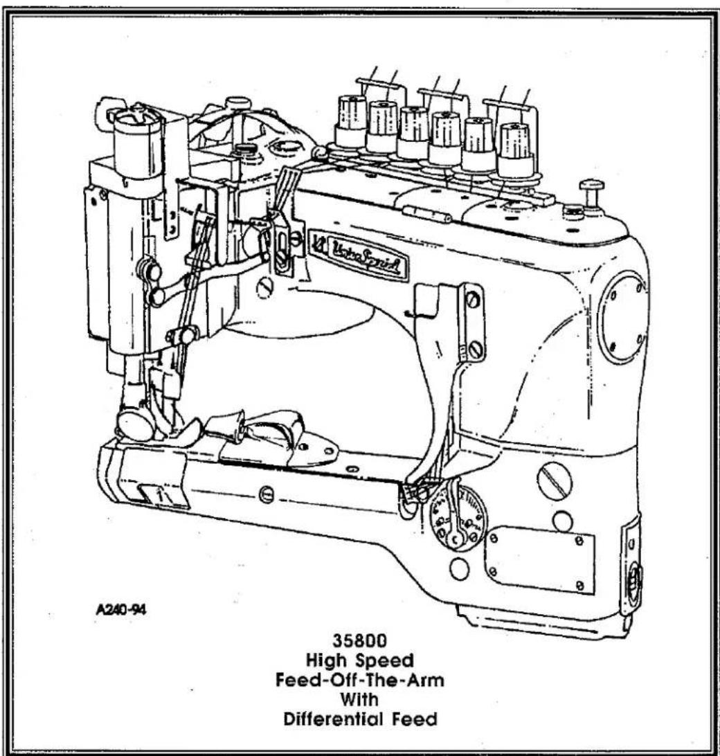
IDENTIFICATION OF MACHINES
Each Union Special machine carries a style number, which on this class machine is stamped in the style plate affixed to the right front of the machine.
The serial number is stamped in the casting at the right rear base of machine.
CLASS DESCRIPTION
High Speed, Feed-Off-The-Arm High Throw Machines, Two or Three Needle, Left Needle In Front, Operator Controlled Differential Feed. Light Weight Presser Bar Mechanism, Adjustable Looper Avoid, Space in Front of Needles 8" (203.2mm), Single Disc Looper Thread Take-Up, Automatic Enclosed Type Oiling System and Filter Type Oil Pump, Visual Sight Oil Action and Supply Gauges, .558" (9/16", 14MM) wide roller.
STYLE OF MACHINES
35800DLW
DOUBLE LAP SEAM. Three needle, low capacity, differential feed with upper driven roller feed (wide roller). -Typical Application- For in and seams on medium weight denim garments. Seam Specification 401 LSc-3. Standard gauge Number 9 (9/64", 3.6mm). Recommended needle 130GS, size 125/049. Maximum recommended speed 4500 R.P.M.. .040 step parts.
35800DWW
DOUBLE LAP SEAM. Two and three needle, high capacity differential feed, high lift feed eccentric, with upper driven, roller feed (wide roller). Feeds have higher teeth on front of feeds. - Typical Application- For use on heavy weight denim garments. Seam Specifications 401 LSc-2 or 401 LSc-3. Standard gauge Numbers 8 (1/8", 3.2mm), 9 (9/64", 3.6mm), 18 (9/32", 7.2mm). Recommended needle 130GS, size 140/054. Maximum recommended speed 4500 R.P.M.. .094 step parts.
NOTE: 18 gauge available with two needles only.
35800DWWL
DOUBLE LAP SEAM. Same as 35800DWW without the folder. Two and three needle, high capacity differential feed, high lift feed eccentric with upper driven roller feed (wide roller). Feeds have higher teeth on front of feeds. - Typical Application- For use on heavy weight denim garments. Seam Specifications 401 LSc-2 or 401 LSc-3. Standard gauge Numbers 8 (1/8", 3.2mm), 9 (9/64", 3.6mm), 18 (9/32", 7.2mm). Recommended needle 130GS size 140/054. Recommended speed 4500 R.P.M.. .094 step parts.
NOTE: 18 gauge available with two needles only.
ILLUSTRATIONS
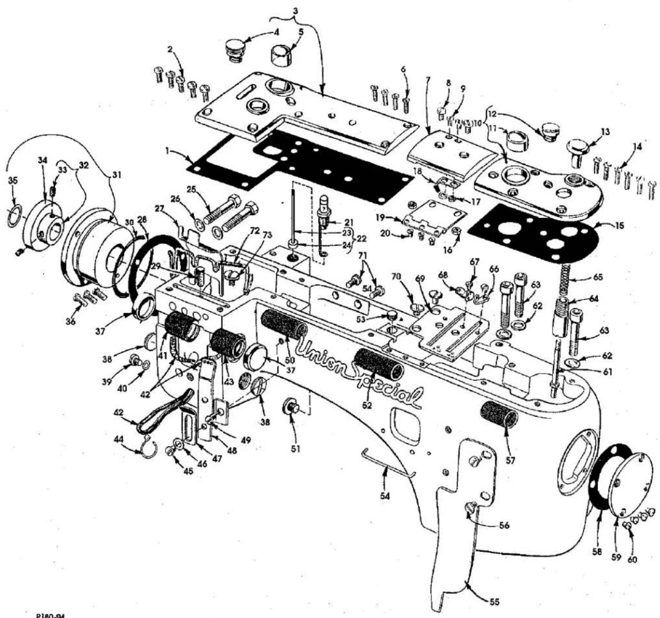
This manual has been arranged to simplify ordering repair parts. Exploded views of various sections of the mechanism are shown so that the parts may be seen in their actual position in the machine. On the page opposite the illustration will be found a listing of the parts with their part numbers, description and the number of pieces required in the particular view being shown.
Numbers in the first column are reference numbers only, and merely indicate the position of the part in the illustration. The reference number should never be used in ordering parts. Always use the part number listed in the second column.
Component parts of sub-assemblies which can be furnished for repairs are indicated by indenting their descriptions under the description of the main sub-assembly. As an example refer to the following text.
-
29126 EC Upper Looper Drive Shaft Assembly .... 1
-
22503 F Screw 1
-
39543 E Cam Follower Locking Clamp .... 1
ILLUSTRATIONS (CONT.)
It will be noted in the previous example that the cam follower, bushing and cam guide and the upper looper drive shaft are not listed. The reason is that replacement of these parts individually is not recommended, so the complete upper looper drive shaft assembly should be ordered.
When a part is common to all machines covered in this manual, no specific usage will be mentioned in the description. However, when the parts for the various machines are not the same, the specific usage will be mentioned in the description and, if necessary, the difference will be shown in the illustration.
A numerical index of all the parts shown in this manual is located at the back. This will facilitate locating the illustration and description when only a part number is known.
IDENTIFYING PARTS
Where the construction permits, each part is stamped with its part number. On some of the smaller parts and on those where construction does not permit, an identification letter is stamped in to distinguish the part from similar ones.
PLEASE NOTE: Part numbers represent the same part, regardless of which manual they appear. On all orders please include part number, name and style of machine for which the part was ordered.
NEEDLES
Each needle has both a type and size number. The type number denotes the kind of shank, point, length, groove, finish and other details. The size number, stamped on the needle shank, denotes the largest diameter of the blade measured between the shank and the eye. Collectively, the type number and size number represent the complete symbol which is given on the label of all needles packed and sold by Union Special.
TYPE
DESCRIPTION
130 GS Short, double groove, struck groove, ball eye, spotted, government point, chromium plated- Sizes available 080/032, 090/036, 100/040, 110/044, 125/049, 140/054, 150/060.
To have needles promptly and accurately filled, an empty package, a needle sample, or the type and size number should be forwarded. Use the description on the label. A complete order should read as follows: "100 needles, type 130 GS, size 125/049".
TERMS
Prices are net cash and subject to change without notice. All shipments are forwarded F.O.B. shipping point. A charge is made to cover postage and insurance.
P180-94
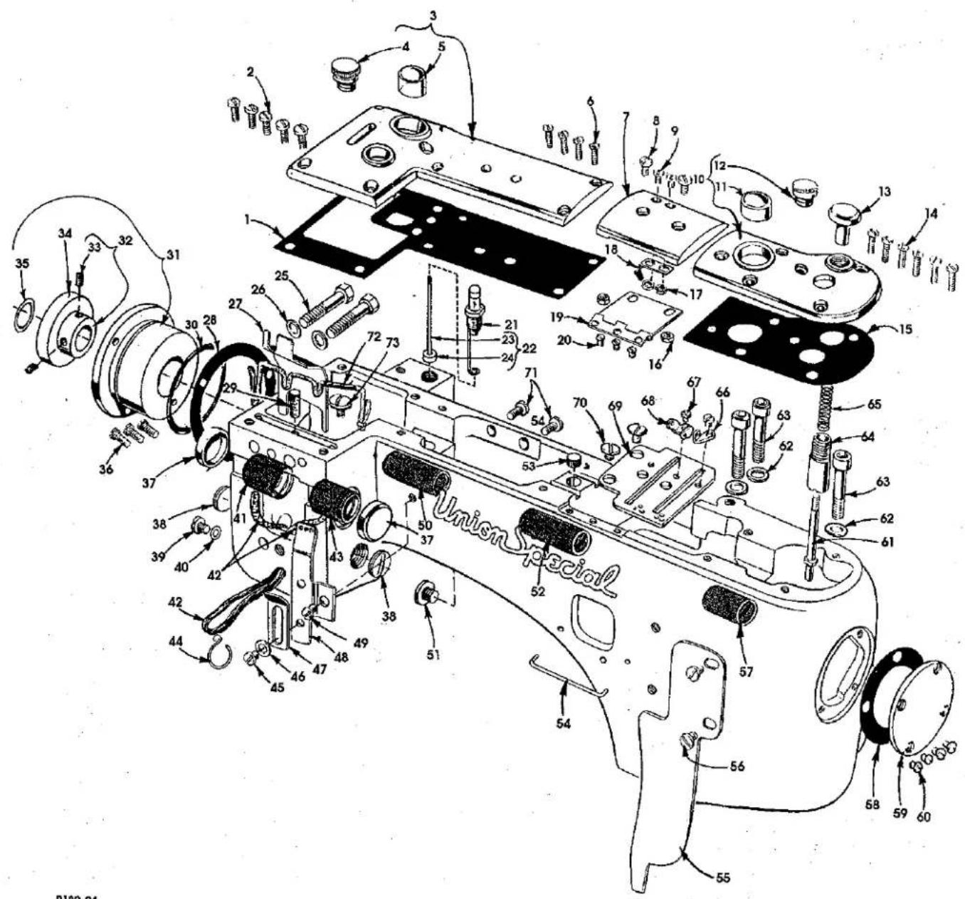
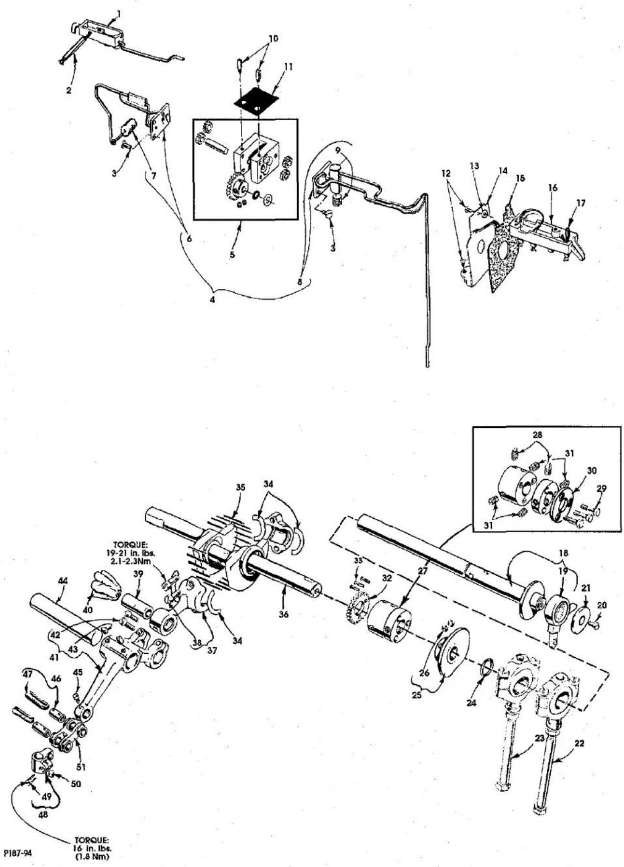
MAIN FRAME, CAST-OFF PLATE, EYELETS, MISCELLANEOUS COVERS AND BUSHINGS
| Ref. | Amt. | ||
| No. | Part No. | Description | Req. |
- 35888 P Gasket 1
- 93 Screw 5
- 35888 NR Crank Chamber Cover 1
- 18-1426 Screw 1
- 50-537 BLK Oil Sight Gauge 1
- 22516 A Screw 4
- 35887 X Top Cover, middle 1
- 93 A Screw 2
- 90 Screw 2
- 35887 AE Top Cover, front 1
- 50-537 BLK Oil Sight Gauge .... 1
- 18-1426 Screw 1
- 35853 Z Looper Throw-Out Plunger Knob 1
- 22516 A Screw 6
- 35887 AD Gasket 1
- 12934 A Nut 2
- 41071 G Nut 2
- 35887 M Spring 1
- 35887 R Middle Top Cover Hinge 1
- 22564 B Screw 3
- 36293 B Oil Sight Gauge 1
- 36293 F Oil Sight Gauge Indicator Assembly 1
- 36293 E Oil Sight Indicator 1
- 39593 C Oil Gauge Float 1
- 22759 A Screw 2
- 6042 A Washer 2
- 35889 H Oil Shield 1
- 56390 E Gasket 1
- C 067 E Cork 1
- 660-1014 "O" Ring 660-955 1
- 35890 M Bearing Housing Assembly 1
- 35890 L Shaft Coupling 1
- 22894 F Screw 2
- 660-1016 Bearing 1
- 660-206 "O" Ring 660-1017 1
- 22569 B Screw 3
- 35761 D Bushing Cap, plastic 2
- 22539 T Plug Screw 2
- 22733 B Oil Drain Screw 1
- 660-935 "O" Ring 660-906 1
- 35760 E Needle Lever Shaft Bushing, rear 1
- CL 21 Oil Wick 2
- 35760 D Needle Lever Shaft Bushing, front 1
- 35897 AW Oil Wicking Hook, upper 1
- 22570 Screw 1
- 8372 A Washer 1
- 35871 A Needle Thread Eyelet, three holes.... 1
- 35871 B Needle Thread Eyelet, three holes 1
- 22570 A Screw 1
- thru 73. See following page
P180-94
MAIN FRAME, CAST-OFF PLATE, EYELETS, MISCELLANEOUS COVERS AND BUSHINGS (CONT.)
| Ref. | Amt. | ||
| No. | Part No. | Description | Req. |
- thru 49. See preceding page
| 50. | 35890 E | Crankshaft Bushing, front | 1 |
| 51. | 22733 B | Main Shaft Bushing, rear | 1 |
| 52. | 35890 D | Plug Screw | 1 |
| 53. | 50-539 BLK | Plug | 1 |
| 54. | 35781 D | Looper Thread Guide Wire | 1 |
| 55. | 35856 AA | Looper Thread Shield | 1 |
| 56. | 22829 | Screw | 2 |
| 57. | 36290 B | Main Shaft Bushing, front | 1 |
| 58. | 35887 V | Gasket | 1 |
| 59. | 35887 Z | Main Frame End Cover | 1 |
| 60. | 22564 B | Screw | 4 |
| 61. | 35853 W | Looper Throw-Out Plunger | 1 |
| 62. | 35876 U | Washer | 3 |
| 63. | 22653 E-20 | Screw | 3 |
| 64. | 35853 AA | Looper Throw-Out Plunger Bushing | 1 |
| 65. | 35853 Y | Looper Throw-Out Plunger Spring | 1 |
| 66. | 35772 T | Cast-Off Plate Eyelet, front | 1 |
| 67. | 28 | Screw | 2 |
| 68. | 35772 S | Cast-Off Plate Eyelet, rear | 1 |
| 69. | 35704 C | Cast-Off Plate | 1 |
| 70. | 22730 | Screw | 2 |
| 71. | 93 | Screw, for rotary pump housing | 2 |
| 72. | CL 21 | Oil Wick | 1 |
| 73. | 22711 | Screw, for oil wick | 1 |
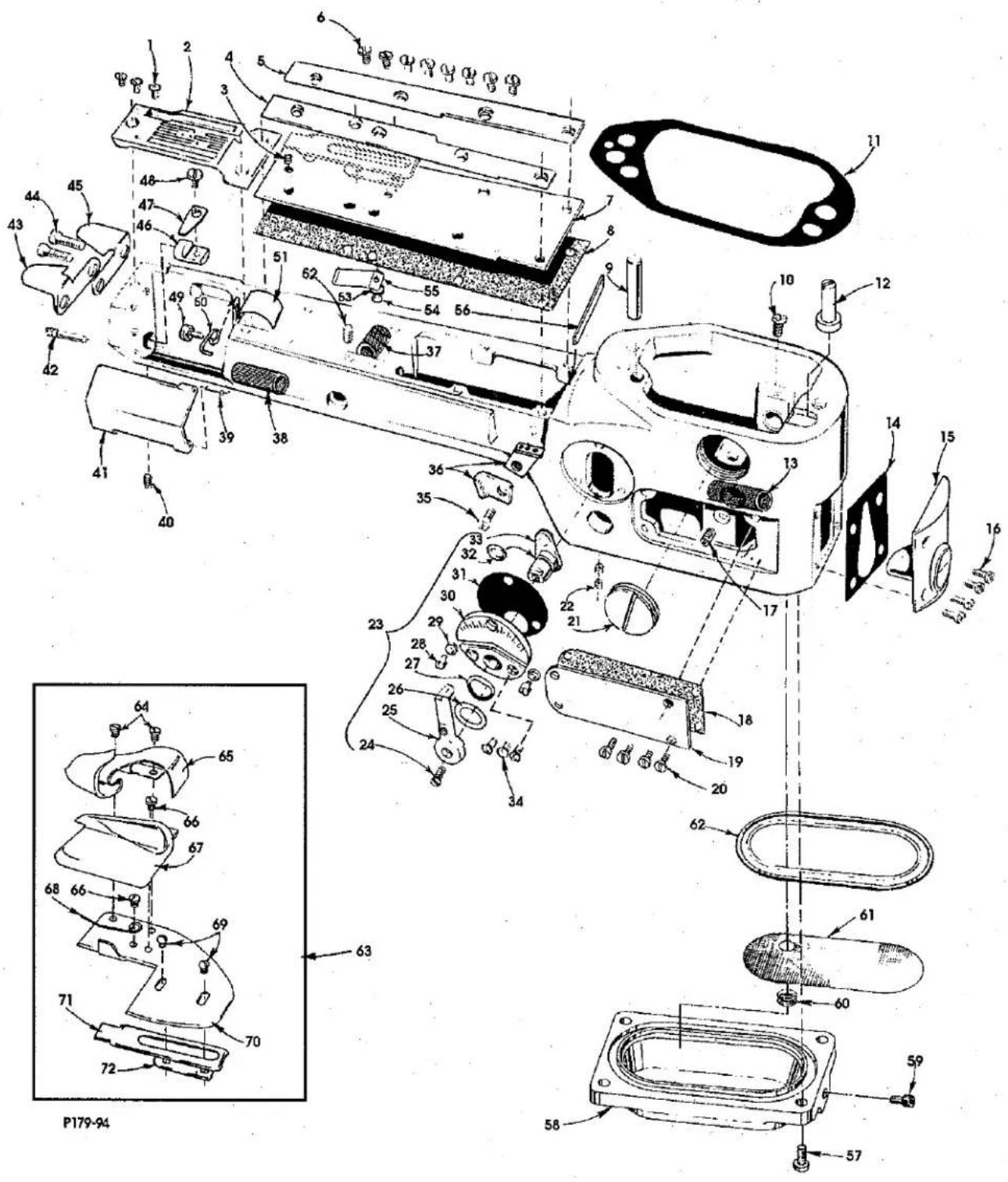
DIFFERENTIAL FEED CONTROL, CYLINDER COVERS AND BUSHINGS (ALL GAUGES)
| Ref. | Amt. | ||
| No. | Part No. | Description | Req. |
- 22524 Screw 3
- ---- Throat Plate (see page 35) .... 1
- 22798 Screw 1
- 35883 N Folder Gib, left 1
- 35883 P Folder Gib, right....1
- 22564 J Screw 8
- 35883 T Cylinder Cover 1
- 35883 S Gasket 1
- 667 D-16 Dowel Pin, straight 1
- 22596 Screw 1
- 36284 Gasket 1
- 36229 A1 Eccentric Stud, for Styles35800DWW, 35800DWWL.... 1
- 36249 A Looper Shaft Bushing, front 1
- 35884 D Gasket 1
- 36284 C Cylinder Cover and Oil Gauge, front 1
- J 87 J Screw 4
- 22560 A Screw 1
- 36286 A Gasket 1
- 36286 Cylinder Side Cover 1
- 22766 Screw 4
- 22539 S Plug Screw 1
- 531 Screw 2
- 29478 CZ Differential Feed Control Assembly 1
- 538 Screw 1
- 36237 K Operating Lever 1
- 652 K-24 Washer, fiber 1
- 36237 J Spring Washer 1
- 36237 H Stop Screw Pin 2
- 60078 Z Nut 2
- 36238 Adjusting Plate 1
- 36238 E Gasket 1
- 660-220 Oil Seal Ring 1
- 36237 E Adjusting Lever 1
- 87 A Screw 3
- 22849 A Screw 1
- 35856 Y Looper Thread Eyelet 2
- 36237 F Bushing, for feed bar eccentric stud....1
- 35850 D Looper Shaft Bushing, rear 1
- 35883 G Pin 1
- 22894 W Screw, for cylinder hinge cover spring support stud .... 1
- 35883 R Cylinder Hinged Cover 1
- 22791 E Screw Pin 1
- 35796 B Chain Cutter Blade, upper 1
- 22747 Screw 2
- 35796 C Chain Cutter Blade, lower 1
- 36283 C Cylinder Hinged Cover Spring Support Stud....1
- 35883 U Cylinder Cover Spring 1
-
22585 C Screw 1
-
thru 72. See following page
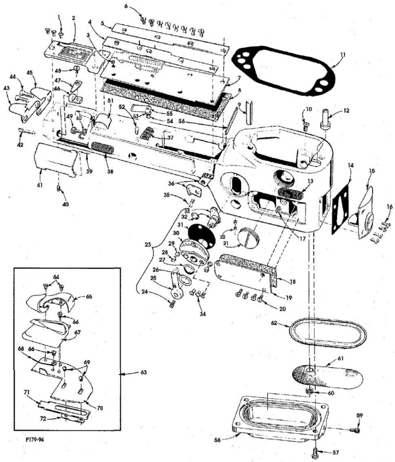
DIFFERENTIAL FEED CONTROL, CYLINDER COVERS AND BUSHINGS (CONT.) (ALL GAUGES)
| Ref. | Amt. | ||
| No. | Part No. | Description | Req. |
- thru 48. See preceding page
| 49. | 22849 | Screw | 1 |
| 50. | 36256 B | Cylinder Looper Thread Guide Wire | 1 |
| 51. | 35884 M | Lower Lint Shield | 1 |
| 52. | 531 | Screw | 1 |
| 53. | 40-107 | Washer | 1 |
| 54. | 22798 | Screw | 1 |
| 55. | 36284 E | Upper Lint Shield | 1 |
| 56. | 35883 V | Gasket | 1 |
| 57. | 22596 | Screw | 4 |
| 58. | 36282 | Bottom Cover | 1 |
| 59. | 22571 E | Screw | 1 |
| 60. | 661-150 | "O" Ring | 1 |
| 61. | 36293 G | Screen | 1 |
| 62. | 36284 F | Gasket | 1 |
| 63. | 23420 CC 18-1/8 | Folder Assembly, for Styles 35800DWW, 35800DLW | 1 |
| 64. | 22513 | Screw | 2 |
| 65. | 23421 CC 18-1/8 | Upper Scroll and Base | 1 |
| 66. | 22760 A | Screw | 2 |
| 67. | 23422 CC 18-1/8 | Lower Scroll | 1 |
| 68. | 23245 | Spring | 1 |
| 69. | 22849 A | Screw | 2 |
| 70. | 642-423 BLK | Base | 1 |
| 71. | 23423 V | Sliding Base | 1 |
| 72. | 23423 W | Clamp, for sliding base | 1 |
P178-94
NEEDLE BAR, NEEDLE HEAD, DETACHABLE HEAD AND MISCELLANEOUS COVERS
| Ref.No. | Part No. | Description | Amt.Req. |
| 1. | 35829 AC | Detachable Head | 1 |
| 2. | 22524 | Screw | 2 |
| 3. | 35767 | Sewing Head Key | 2 |
| 4. | 35859 L | Needle Bar Bushing, lower | 1 |
| 5. | 22653 B-8 | Screw | 3 |
| 6. | 667 C-12 | Dowel Pin | 2 |
| 7. | 35859 K | Needle Bar Bushing, upper | 1 |
| 8. | 35831 G | Presser Bar Bushing, lower | 1 |
| 9. | 667 B-20 | Dowel Pin | 2 |
| 10. | 22653 B-16 | Screw | 2 |
| 11. | 35876 AA | Puller Clutch Bracket | 1 |
| 12. | 22894 C | Screw | 1 |
| 13. | 35889 AA | Gasket | 1 |
| 14. | 35889 Y | Head Cover, left | 1 |
| 15. | 6042 A | Washer | 1 |
| 16. | 664 F-16 | Dowel Pin, tapered | 1 |
| 17. | 318 | Screw | 1 |
| 18. | 35889 Z | Detachable Head Cover, front | 1 |
| 19. | 22564 B | Screw | 2 |
| 20. | 22829 | Screw | 2 |
| 21. | 22513 | Screw | 8 |
| 22. | 35731 A | Presser Bar Guide Plate | 4 |
| 23. | 35897 AW | Oil Wicking Hook | 1 |
| 24. | CL 21 | Oil Wick | 1 |
| 25. | 35817 E | Needle Bar, marked "DY" | 1 |
| 26. | 35818 BY-8 | Needle Bar Head, marked "V-8", for all 8 gauge Styles | 1 |
| 35818 BY-9 | Needle Bar Head, marked "V-9", for all 9 gauge Styles | 1 | |
| 27. | 605 | Screw | 3 |
| 28. | 57 WD | Screw | 1 |
| 29. | 15438 C | Needle Thread Nipper Spring | 1 |
| 30. | 57 WB | Needle Thread Nipper Spring Plate | 1 |
| 31. | 605 | Screw | 1 |
| 32. | 43296 | Needle Thread Nipper Base | 1 |
| 33. | 35869 L | Thread Controller Arm | 1 |
| 34. | 89 | Screw | 2 |
| 35. | 12934 A | Nut | 1 |
| 36. | 69 H | Washer | 2 |
| 37. | 22758 E | Screw | 2 |
| 38. | 35869 D | Control Lever Connection Link | 1 |
| 39. | 22557 A | Screw | 1 |
| 40. | 35869 K | Needle Thread Lever Control Eyelet | 1 |
| 41. | 25 B | Screw | 1 |
| 42. | 35869 C | Needle Thread Control Lever | 1 |
| 43. | 22768 | Screw | 2 |
| 44. | 35870 | Needle Thread Take-up | 1 |
| 45. | 22524 | Screw | 2 |
| 46. | 35889 X | Detachable Head Cover, front | 1 |
| 47. | 35889 B | Gasket | 1 |
| 48. | 12982 | Nut | 1 |
| 49. | 22768 | Screw | 2 |
| 50. | 35854 | Needle Bar Guard | 1 |
| 51. | 77 | Screw | 2 |
| 52. | 35864 F | Needle Lever Thread Eyelet | 1 |
| 53. | 35889 G | Baffle Plate | 1 |
MISCELLANEOUS OILING, NEEDLE LEVER, CRANKSHAFT AND MAIN SHAFT PARTS (ALL GAUGES)
| Ref. No. | Part No. | Description | Amt. Req. |
| 1. | 35894 V | Oil Reservoir, back | 1 |
| 2. | 35897 BU | Oil Reservoir Outlet Tube | 1 |
| 3. | 22585 A | Screw | 6 |
| 4. | 29472 AD | Oil Pump Assembly | 1 |
| 5. | 29472 AC | Oil Pump | 1 |
| 6. | 35897 CC | Oil Pump Assembly Cover, rear, for oil pump assembly | 1 |
| 7. | 35897 BV | Intake Filter | 1 |
| 8. | 35897 CH | Oil Pump Housing Cover, front | 1 |
| 9. | 22571 B | Plug Screw | 1 |
| 10. | 21756 G | Vent Screw, for oil pump | 2 |
| 11. | 35897 BW | Gasket | 1 |
| 12. | 90 | Screw | 2 |
| 13. | 80265 | Spacer Washer | 1 |
| 14. | 36261 B | Take-up Shield | 1 |
| 15. | 35861 D | Gasket | 1 |
| 16. | 35894 K | Oil Reservoir, front | 1 |
| 17. | WO 3 | Oil Wick | 1 |
| 18. | 29478 DZ | Looper Drive Connecting Rod Assembly (see page 25, ref. no.43) | 1 |
| 19. | 35853 AJ | Looper Drive Connection | 1 |
| 20. | 22526 | Screw | 1 |
| 21. | 35895 V | Washer | 1 |
| 22. | 29478 EC | Feed Drive Eccentric Assembly | 1 |
| 23. | 29478 DV | Feed Lift Eccentric Assembly, for Style 35800DLW (see page 21, ref. no. 13) | 1 |
| 29478 EB | Feed Lift Eccentric Assembly, for Styles 35800DWW, 35800DWWL (see page 21, ref. no. 13) | 1 | |
| 24. | 660-202 | Oil Seal Ring | 1 |
| 25. | 35723 C | Looper Thread Take-Up | 1 |
| 26. | 22580 D | Screw | 2 |
| 27. | 35895 W | Main Shaft and Crankshaft Coupling | 1 |
| 28. | 22894 K | Spot Screw | 2 |
| 29. | 22519 F | Screw | 3 |
| 30. | 35895 Z | Washer Plate | 1 |
| 31. | 22894 J | Set Screw | 4 |
| 32. | 35897 BY | Oil Pump Driving Gear | 1 |
| 33. | 22797 | Screw | 3 |
| 34. | 35763 G | Needle Bearing Retainer | 4 |
| 35. | 35763 F | Needle Bearing | 28 |
| 36. | 35822 W | Crankshaft | 1 |
| 37. | 35862 | Needle Lever Connecting Rod | 1 |
| 38. | 22587 B | Screw | 2 |
| 39. | 35763 | Needle Lever Connecting Rod Pin | 1 |
| 40. | WO 3 | Oil Wick | 1 |
| 41. | 35815 A | Needle Lever | 1 |
| 42. | 22729 | Screw | 2 |
| 43. | 22596 B | Screw | 2 |
| 44. | 35761 | Needle Lever Shaft | 1 |
| 45. | 77 | Screw | 1 |
| 46. | 51054 | Link Pin | 2 |
| 47. | 666-149 | Oil Wick | 2 |
| 48. | 51254 J | Needle Bar Connection | 1 |
| 49. | 22562 A | Screw | 1 |
| 50. | 22564 | Screw | 1 |
| 51. | 56354 A | Needle Lever Link | 1 |
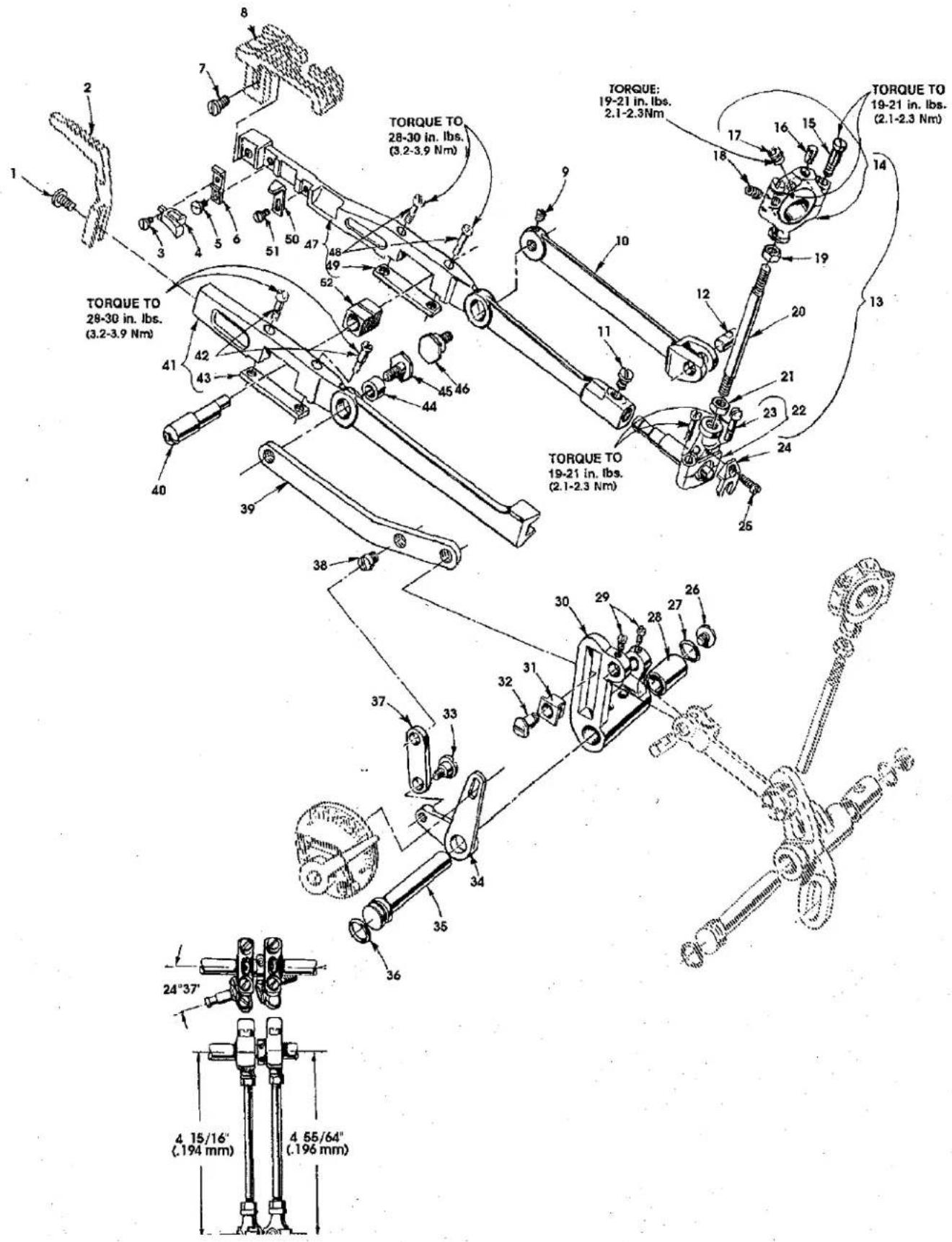
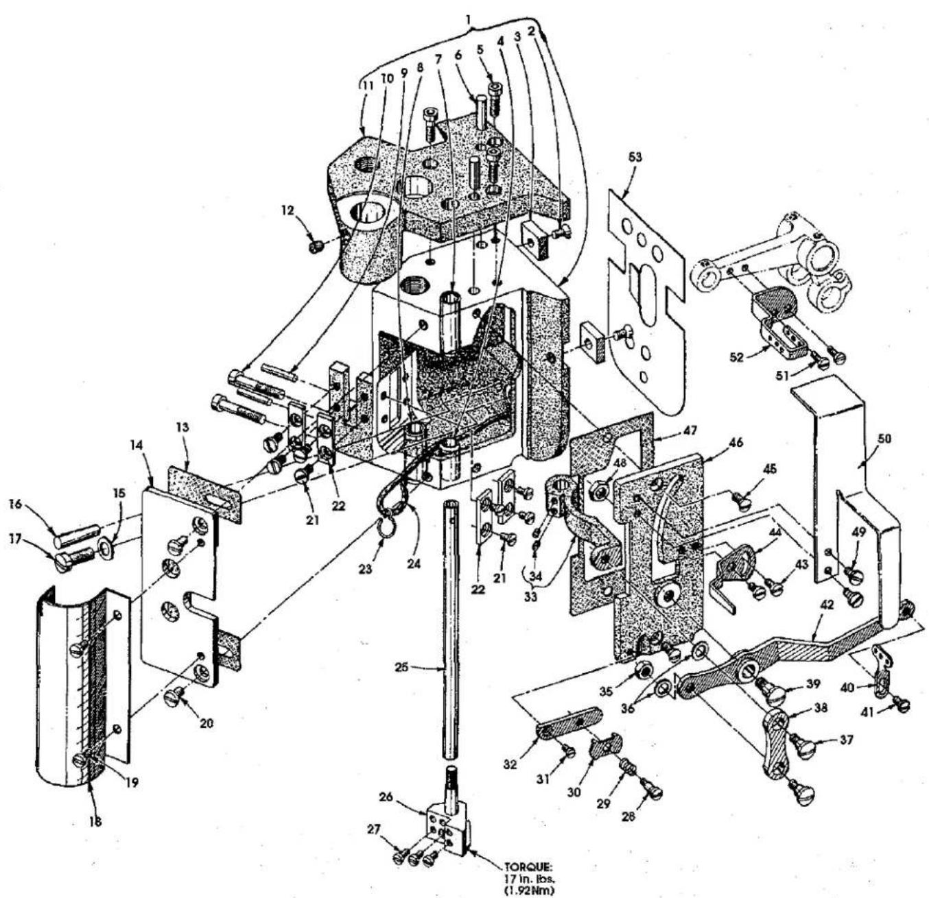
DIFFERENTIAL FEED BAR, MAIN FEED BAR, FEED LIFT ECCENTRIC ASSEMBLY (ALL GAUGES)
| Ref. No. | Part No. | Description | Amt. Req. |
| 1. | 22528 | Screw | 1 |
| 2. | ---- | Differential Feed Dog (see page 35) | 1 |
| 3. | 87 U | Screw | 1 |
| 4. | 35825 AC | Needle Guard | 1 |
| 5. | 22768 | Screw | 1 |
| 6. | 35835 B | Needle Guard Holder | 1 |
| 7. | 22528 | Screw | 1 |
| 8. | ---- | Main Feed Dog (see page 35) | 1 |
| 9. | 22894 P | Screw | 1 |
| 10. | 35834 W | Main Feed Bar Driving Link | 1 |
| 11. | 33174 B | Screw | 1 |
| 12. | 62238 A | Link Pin | 1 |
| 13. | 29478 EB | Feed Lift Eccentric Assembly, for Styles 35800DWW, 35800DWWL | 1 |
| - | 29478 DV | Feed Lift Eccentric Assembly, for Style 35800DLW | 1 |
| 14. | 29103 U | Feed Lift Eccentric Assembly Ball Joint, for Styles 35800DWW, 35800DWWL | 1 |
| - | 29103 T | Feed Lift Eccentric Assembly Ball Joint, for Style35800DLW | 1 |
| 15. | 22587 E | Screw | 2 |
| 16. | WO 3 | Oil Wick | 1 |
| 17. | 22894 W | Set Screw | 2 |
| 18. | 22894 AA | Spot Screw | 1 |
| 19. | 269 | Nut, left thread | 1 |
| 20. | 36244 | Connecting Rod | 1 |
| 21. | 18 | Nut, right thread | 1 |
| 22. | 36244 A | Ball Joint, complete | 1 |
| 23. | 22729 C | Screw | 2 |
| 24. | 41255 B | Ball Fork | 1 |
| 25. | 22747 | Screw | 1 |
| 26. | 22711 | Screw | 1 |
| 27. | 660-206 | Oil Seal Ring | 1 |
| 28. | 36236 B | Bushing, for feed rocker shaft | 1 |
| 29. | 77 | Screw | 2 |
| 30. | 35836 A | Feed Rocker | 1 |
| 31. | 36236 K | Differential Feed Driving Link Slide Block | 1 |
| 32. | 36236 J | Differential Feed Bar Driving Link Stud | 1 |
| 33. | 22504 C | Screw | 1 |
| 34. | 36237 | Differential Feed Adjusting Lever | 1 |
| 35. | 36236 A | Feed Rocker Shaft | 1 |
| 36. | 660-207 | Oil Seal Ring | 1 |
| 37. | 36237 A | Differential Feed Adjusting Lever Link | 1 |
| 38. | 22845 M | Screw | 1 |
| 39. | 35836 B | Differential Feed Bar Driving Link | 1 |
| 40. | 36234 D | Feed Bar Eccentric Stud | 1 |
| 41. | 36234 F | Differential Feed Bar | 1 |
| 42. | 22587 H | Screw | 2 |
| 43. | 36234 G | Feed Bar Plate | 1 |
| 44. | 36236 H | Bushing | 1 |
| 45. | 36236 G | Differential Feed Bar Driving Link Stud | 1 |
| 46. | 35834 X | Main Feed Bar Ecentric Driving Stud | 1 |
| 47. | 35834 AB | Main Feed Bar | 1 |
| 48. | 22587 H | Screw | 2 |
| 49. | 36234 G | Feed Bar Plate | 1 |
| 50. | 35834 AC | Main Feed Dog Support, for Styles35800DWW, 35800DWWL | 1 |
| 35834 AA | Main Feed Dog Support, for Style 35800DLW | 1 | |
| 51. | 22804 | Screw | 1 |
| 52. | 36234 C | Feed Bar Slide Block | 1 |
LOOPERS, LOOPER HOLDERS, FEED DRIVE ASSEMBLY AND LOOPER AVOID ASSEMBLY
| Ref. | Amt. | ||
| No. | Part No. | Description | Req. |
- 35848 B Looper Holder, for left needle looper, marked "A".... 1
- 22562 A Screw 1
- 22564 Screw 1
- 35848 E Looper Holder, for right needle looper, marked "D" 1
- 22562 A Screw 1
- 22564 Screw 1
- 35848 D Looper Holder, for middle needle looper, marked "C" ..... 1
- 22562 A Screw
- 22564 Screw 1
- 35809 AY Looper, for middle needle, marked "AV" 1
- 35808 AY Looper, for right needle, marked "AU" 1
- 35809 BY Looper, for left needle, marked "AY" 1
- 35849 C Looper Rocker Shaft 1
- 35836 C Feed Rocker Driving Link Screw 1
- 660-207 Oil Seal Ring 1
- 36236 A Feed Drive Shaft 1
- 258 A Nut 1
- 36236 H Bushing, for feed rocker driving link 1
- 36236 C Feed Rocker Driving Link 1
- 62238 A Link Pin 1
- 29478 EC Feed Drive Assembly 1
- 18 Nut, right hand thread 1
- 43246 Connecting Rod 1
- 269 Nut, left hand thread 1
- 29101 K Feed Drive Eccentric Assembly 1
- WO 3 Oil Wick 1
- 35840 Eccentric Bearing 1
- 22587 E Screw 2
- 35839 C Eccentric 1
- 22894 U Screw 1
- 22894 W Screw 2
- 35842 L Feed Drive Rocker Assembly 1
- 22729 C Screw 2
- 22747 Screw 2
- 35840 A Shell 1
- 35846 D Guide 1
- 35842 K Feed Drive Looper Avoid Assembly 1
- 36236 B Bushing 1
-
35866 Nut 1
-
thru 61. See following page
LOOPERS, LOOPER HOLDERS, FEED DRIVE ASSEMBLY AND LOOPER AVOID ASSEMBLY (CONT.)
| Ref. | Amt. | ||
| No. | Part No. | Description | Req. |
- thru 39. See preceding page
| 40. | 660-206 | Oil Seal Ring | 1 |
| 41. | 22711 | Screw | 1 |
| 42. | 35766 B | Nut | 1 |
| 43. | 29478 DZ | Looper Drive Connecting Rod Assembly | 1 |
| 44. | 35853 V-156 | Hinge Pin | 1 |
| 45. | 660-310 | Truarc Ring | 2 |
| 46. | 56341 G | Locking Spring | 1 |
| 47. | 50-458 BLK | Pin | 1 |
| 48. | 35853 AK | Looper Drive Connecting Rod | 1 |
| 49. | 22729 D | Screw | 2 |
| 50. | 36278 C | Stud, for looper shaft sleeve | 1 |
| 51. | 29478 DM | Looper Avoid Link Assembly | 1 |
| 52. | 35851 K | Screw | 2 |
| 53. | P 51-184 BLK | Ferrule | 2 |
| 54. | 35851 M | Connecting Rod Bearing Shell | 1 |
| 55. | 660-311 | Needle Bearing | 2 |
| 56. | 22560 A | Screw | 1 |
| 57. | 36249 B | Looper Shaft Sleeve | 1 |
| 58. | 22729 D | Screw | 1 |
| 59. | 652 C-9 | Washer | 1 |
| 60. | 35751 G | Looper Shaft Collar | 1 |
| 61. | 22572 B | Screw | 1 |
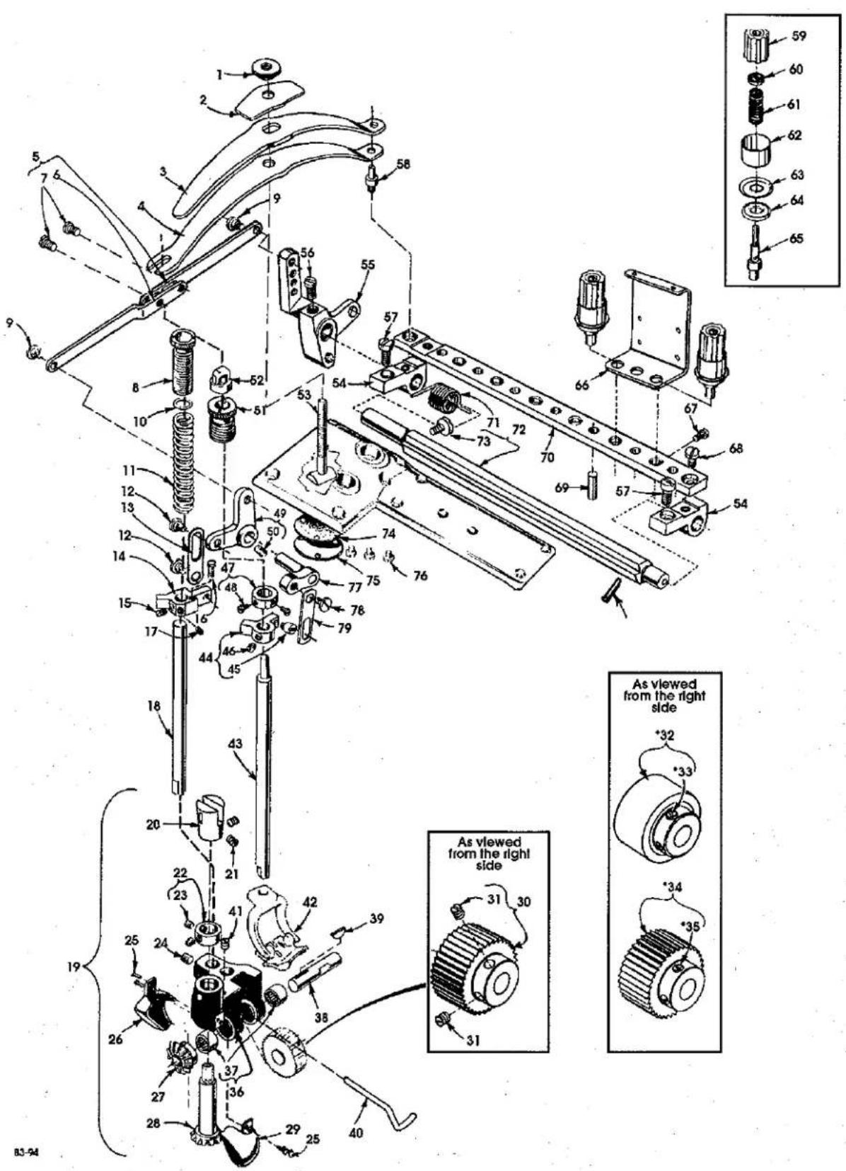
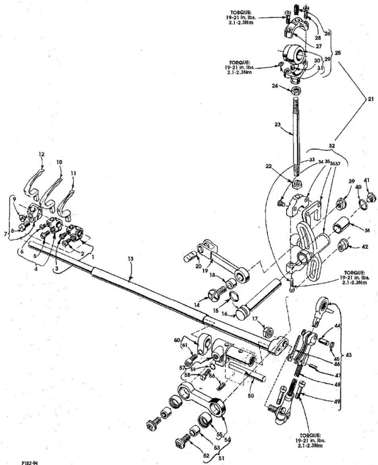
UPPER ROLLER FEED, FOOT LIFTER AND THREAD TENSION PARTS
| Ref. | Amt. | ||
| No. | Part No. | Description | Req. |
| 1. | 35733 B | Presser Regulating Screw | 1 |
| 2. | 35833 C | Presser Spring Plate | 1 |
| 3. | 35833 E | Presser Spring, upper | 1 |
| 4. | 35833 D | Presser Spring, lower | 1 |
| 5. | 36280 V | Lifter Lever Link Assembly | 1 |
| 6. | 36280 U | Lifter Lever Link | 1 |
| 7. | 22585 C | Screw | 2 |
| 8. | 61257 G | Roller Presser Spring Regulator | 1 |
| 9. | 86 | Screw | 2 |
| 10. | 61256 G | Roller Presser Spring Washer | 1 |
| 11. | 35873 Z | Roller Presser Spring | 1 |
| 12. | 22758 C | Screw | 2 |
| 13. | 35880 K | Lifter Lever Bell Crank Link | 1 |
| 14. | 35873 AH | Presser Bar Connection | 1 |
| 15. | 89 | Screw | 1 |
| 16. | 22764 | Screw | 1 |
| 17. | 22764 A | Screw | 1 |
| 18. | 35873 W | Roller Presser Bar | 1 |
| 19. | 29478 ED | Puller Assembly | 1 |
| 20. | 54274 C | Feed Roller Upper Connection | 1 |
| 21. | 22894 W | Screw | 2 |
| 22. | 14649 | Drive Gear Collar | 1 |
| 23. | 88 | Screw | 2 |
| 24. | 22894 C | Screw | 1 |
| 25. | 22738 | Screw | 4 |
| 26. | 35875 AA | Gear Guard, front | 1 |
| 27. | 35875 X | Driven Miter Gear | 1 |
| 28. | 35875 Y | Drive Miter Gear | 1 |
| 29. | 35875 Z | Gear Guard, rear | 1 |
| 30. | 35826 X | Feed Roller | 1 |
| 31. | 22560 B | Screw | 2 |
| 32. | 35826 DZ | Wide Rubber Roller | 1 |
| 33. | 22560 B | Screw | 2 |
| 34. | 35826 CB | Feed Roller, reverse teeth | 1 |
| 35. | 22560 B | Screw | 2 |
| 36. | 35873 AJ | Feed Roller Frame | 1 |
| 37. | 660-303 | Needle Bearing | 1 |
| 38. | 35873 AK | Feed Roller Shaft | 1 |
| 39. | 35877 AA | Woodruff Key | 1 |
| 40. | 21237 ES | Air Blower Tube | 1 |
| 41. | 73 C | Screw | 1 |
| 42. | Presser Foot (see page 35) | 1 | |
| 43. | 35878 S | Presser Bar | 1 |
| 44. | 35831 C | Presser Bar Lifter and Guide | 1 |
| 45. | 402 | Screw | 1 |
| 46. | 22560 B | Screw | 1 |
- thru 79. See following page
* Items can be purchased as an extra send charge.
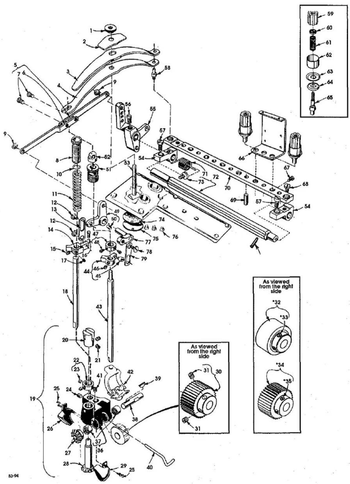
UPPER ROLLER FEED, FOOT LIFTER AND THREAD TENSION PARTS (CONT.)
| Ref. | Amt. | ||
| No. | Part No. | Description | Req. |
- thru 46. See preceding page
| 47. | 52888 B | Collar | 1 |
| 48. | 22562 | Screw | 2 |
| 49. | 35880 P | Lifter Lever Bell Crank | 1 |
| 50. | 22894 J | Screw | 1 |
| 51. | 35878 H | Presser Bar Spring and Spring Regulator | 1 |
| 52. | 55287 L | Presser Spring Rest | 1 |
| 53. | 35878 F | Presser Spring Regulating Screw | 1 |
| 54. | 36292 M | Tension Plate Bracket | 2 |
| 55. | 36280 W | Lifter Lever | 1 |
| 56. | 22839 D | Screw | 1 |
| 57. | 136 | Screw | 2 |
| 58. | 35833 F | Presser Spring Rest | 1 |
| 59. | C 50092 S | Tension Nut | 6 |
| 60. | 39592 AK | Tension Post Ferrule | 6 |
| 61. | 51292 F-4 | Looper Thread Tension Spring, for looper | 3 |
| 110-3 | Needle Thread Tension Spring, for needle | 3 | |
| 62. | 56392 F | Shield, tension spring | 6 |
| 63. | 35792 | Tension Disc, large | 6 |
| 64. | 109 | Tension Disc, small | 6 |
| 65. | 36292 P | Tension Post | 6 |
| 66. | 36298 G | Tension Thread Eyelet | 3 |
| 67. | 22562 A | Screw | 6 |
| 68. | 94 | Screw | 1 |
| 69. | 35792 T | Tension Disc Release Pin | 7 |
| 70. | 36298 F | Tension Support | 1 |
| 71. | 36292 K | Tension Release Shaft Spring | 1 |
| 72. | 36292 N | Tension Release Shaft | 1 |
| 73. | 22784 F | Screw | 1 |
| 660-219 S | Roll Pin, (not shown) | 1 | |
| 74. | 35888 M | Gasket | 1 |
| 75. | 35888 L | Cover Plate | 1 |
| 76. | 98 A | Screw | 3 |
| 77. | 35880 N | Presser Bar Litter Lever | 1 |
| 78. | 22758 C | Screw | 1 |
| 79. | 35880 L | Lifter Lever Connecting Link | 1 |
P185-94
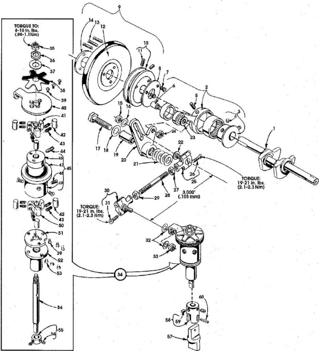
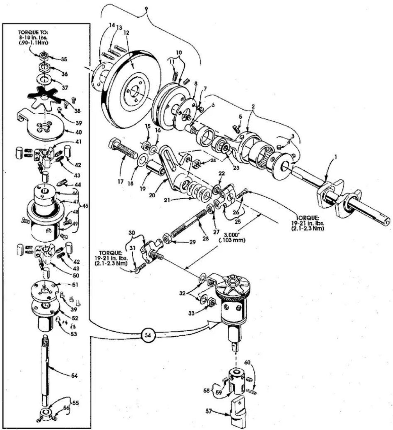
PULLEY, CRANKSHAFT, CLUTCH AND CLUTCH DRIVING MECHANISM
| Ref. | Amt. | ||
| No. | Part No. | Description | Req. |
- 35822 W CrankShaft 1
- 29480 ALY Connecting Rod and Clutch Driving Eccentric Assembly 1
- 35877 XA Eccentric 1
- 22894 C Screw 2
- 666-186 Oil Wick 1
- 50342 V Shoulder Screw 1
- 22589 Screw 3
- 35821 V Washer 1
- 35821 S Pulley Assembly 1
- 35821 F Pulley 1
- 22894 E Set Screw 2
- 61321 J Handwheel 1
- 22574 Screw 3
- 61321 L Clamp Plate
- 258 Nut 1
- 20 Washer 1
- 22644 K-80 Screw
- 61351 C Washer 1
- 35877 N Segment Lever Bushing 1
- 35877 Z Clutch Driving Segment Lever 1
- 61351 C Washer 4
- 36 G Washer 1
- 6042 A Washer 1
- 258 Nut 1
- 35876 V Ball Joint Assembly, right 1
- 22729 C Screw 2
- 269 Nut, left hand thread 1
- 4761 Roller Clutch Connecting Rod 1
- 18 Nut, right hand thread 1
- 22894 W Roller Clutch Ball Joint Assembly, left 2
- 22729 C Screw 2
- 20 Washer 2
-
18 Nut 1
-
thru 60. See following page
P185-94
PULLEY, CRANK SHAFT, CLUTCH AND CLUTCH DRIVING MECHANISM (CONT.)
| Ref. | Amt. | ||
| No. | Part No. | Description | Req. |
- thru 33. See preceding page
| 34. | 29478 BY | Constant Wedge Angle Clutch Assembly | 1 |
| 35. | 18 | Nut | 1 |
| 36. | 11638 M | Nut | 1 |
| 37. | 61351 C | Washer | 1 |
| 38. | 54274 N | Brake Spring | 1 |
| 39. | 605 A | Screw | 6 |
| 40. | 35876 AC | Clutch Drive Lever | 1 |
| 41. | 54274 H | Clutch Disc, upper | 1 |
| 42. | 54274 L | Clutch Roller | 6 |
| 43. | 54274 Y | Clutch Roller Spring and Wear Cap | 12 |
| 44. | 22894 H | Spot Screw | 1 |
| 45. | 35876 AB | Barrel Assembly | 1 |
| 46. | 50-835 BLK | Barrel Core | 1 |
| 47. | 35876 AD | Drive Lever Brake | 1 |
| 48. | 538 | Screw | 3 |
| 49. | 50-834 BLK | Barrel | 1 |
| 50. | 54274 H | Clutch Disc, lower | 1 |
| 51. | 35876 AG | Locking Spacer Plate | 1 |
| 52. | 35876 AF | Lower Bearing | 1 |
| 53. | 22564 | Screw | 3 |
| 54. | 35876 AE | Feed Drive Shaft | 1 |
| 55. | 41363 U | Collar | 1 |
| 56. | 22743 | Screw | 2 |
| 57. | 54279 | Feed Roller Drive Floating Connection | 1 |
| 58. | 35876 AH | Feed Roller Connection, upper | 1 |
| 59. | 22560 B | Screw | 2 |
| 60. | 660-219 | Roll Pin | 1 |
PI93-94
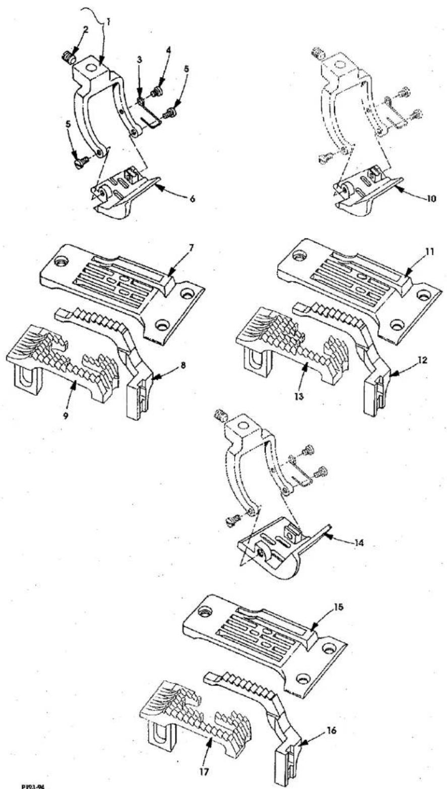
PRESSER FOOT, THROAT PLATE, FEED DOGS
| Ref. | Amt. | ||
| No. | Part No. | Description | Req. |
-
35874 B Presser Foot Fork 1
-
22894 C Screw 1
-
35830 K Spring 1
-
22599 Screw 1
-
22845 A Screw 2
-
35830 DWW8 Presser Foot, for Styles 35800DWW8, DWWL8 1
- 35830 DWW9 Presser Foot, for Styles 35800DWW9, DWWL9 1
- 35824 DX8 Throat Plate, for Stlyes 35800DWW8, DWWL8 1
- 35824 DX9 Throat Plate; for Styles 35800DWW9; DWWL9 1
-
35826 DX Differential Feed Dog, for Styles 35800DWW8, 9, DWWL 8, 9 ...... 1
-
35805 DX Main Feed Dog, for Styles 35800DWW8, 9, DWWL8, 9 .... 1
-
35830 DWW18 Presser Foot, for Styles 35800DWW18, DWWL18 .... 1
-
35824 DW18 Throat Plate, for Styles 35800DWW18, DWWL18 1
-
35826 DX Differential Feed Dog, for Styles 35800DWW18, DWWL18 .... 1
-
35805 DW18 Main Feed Dog, for Styles 35800DWW18, DWWL18 .... 1
-
35820 BQW9 Presser Foot, for Style 35800DLW9 1
-
35824 BQW9 Throat Plate, for Style 35800DLW9 1
-
35826 DLW9 Differential Feed Dog, for Style 35800DLW9 1
-
35805 DLW Main Feed Dog, for Style 35800DLW9 1
P191-94
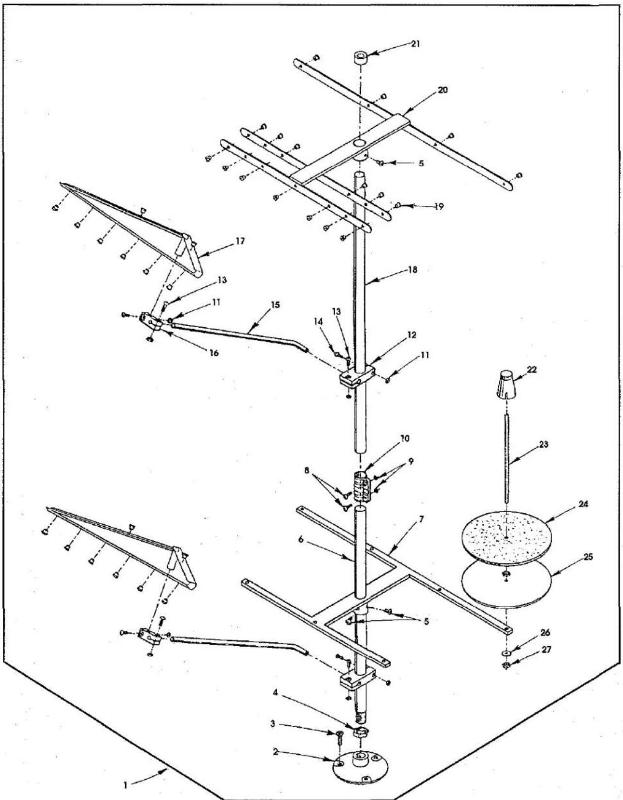
THREAD STAND
| Ref. | Amt. | ||
| No. | Part No. | Description | Req. |
- 21101 S7 Thread Stand, complete 1
- Thread Stand Base 1
- Screw 3
- Nut 1
- Screw 4
- Thread Stand Rod, short 1
- Base Bracket 1
- Screw 2
- Nut 2
- Joint 1
- Nut 8
- Holder, large 2
- Screw 6
- Screw, long 2
- Thread Guide Rod 2
- Holder, thread guide 2
- Thread Guide 2
- Thread Stand Rod, long 1
- Thread Eyelet 34
- Thread Guide 1
- Cap 1
- Spool Retainer 7
- Spool Pin 7
- Felt Disc 7
- Support Disc 7
- Spring Washer 7
- Nut 14
P186-94
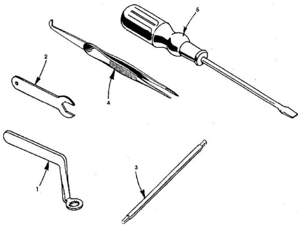
ACCESSORIES
| Ref. No. | Part No. | Description | Amt. Req. |
- TT 85 Wrench, for looper avoid .... 1
- 21388 AZ Wrench, for feed bar 1
- 21227 AR Needle Head Torque Rod 1
- 660-240 Thread Tweezers 1
- 21201 Screwdriver 1
- 660-457 Plastic Cover (not shown) 1
- 28604 R Oil Can (not shown) 1
- 660-1012 Oil Can Nozzle (not shown) 1
- WR 56 Allen Wrench, size 1/4" (not shown) 1
- WR 58 Allen Wrench, size 3/8" (not shown) 1
- WR 60 Allen Wrench, size 1/2" (not shown) 1
NOTES
NOTES
NOTES
NUMERICAL INDEX OF PARTS
| Part No. Page No. | Part No. Page No. | Part No. Page No. | Part No. Page No. |
| 109......29 | 22738......27 | 35723 C......19 | 35835 B......21 |
| 110-3......29 | 22743......33 | 35731 A......17 | 35836 A......21 |
| 11638 M......33 | 22747......13, 21, 23 | 35733 B......27 | 35836 B......21 |
| 12934 A......9, 17 | 22758 C......27, 29 | 35751 G......25 | 35836 C......23 |
| 12982......17 | 22758 E......17 | 35760 D......9 | 35839 C......23 |
| 136......29 | 22759 A......9 | 35760 E......9 | 35840......23 |
| 14649......27 | 22760 A......15 | 35761......19 | 35840 A......23 |
| 15438 C......17 | 22764......27 | 35761 D......9 | 35842 K......23 |
| 18......21, 23, 31, 33 | 22764 A......27 | 35763......19 | 35842 L......23 |
| 18-1426......9 | 22766......13 | 35763 F......19 | 35846 D......23 |
| 20......31 | 22768......17, 21 | 35763 G......19 | 35848 B......23 |
| 21101 S7......37 | 22784 F......29 | 35766 B......25 | 35848 D......23 |
| 21201......38 | 22791 E......13 | 35767......17 | 35848 E......23 |
| 21227 AR......38 | 22797......19 | 35772 S......11 | 35849 C......23 |
| 21237 ES......27 | 22798......13, 15 | 35772 T......11 | 35850 D......13 |
| 21388 AZ......38 | 22804......21 | 35781 D......11 | 35851 K......25 |
| 21756 G......19 | 22829......11, 17 | 35792......29 | 35851 M......25 |
| 22504 C......21 | 22839 D......29 | 35792 T......29 | 35853 AA......11 |
| 22513......15, 17 | 22845 A......35 | 35796 B......13 | 35853 AJ......19 |
| 22516 A......9 | 22845 M......21 | 35796 C......13 | 35853 AK......25 |
| 22519 F......19 | 22849......15 | 35805 DLW......35 | 35853 V-156......25 |
| 22524......13, 17 | 22849 A......13, 15 | 35805 DW18......35 | 35853 W......11 |
| 22526......19 | 22894 AA......21 | 35805 DX......35 | 35853 Y......11 |
| 22528......21 | 22894 C......17, 27, 31, 35 | 35808 AY......23 | 35853 Z......9 |
| 22539 S......13 | 22894 E......31 | 35809 AY......23 | 35854......17 |
| 22539 T......9 | 22894 F......9 | 35809 BY......23 | 35856 AA......11 |
| 22557 A......17 | 22894 H......33 | 35815 A......19 | 35856 Y......13 |
| 22560 A......13, 25 | 22894 J......19, 29 | 35817 E......17 | 35859 K......17 |
| 22560 B......27, 33 | 22894 K......19 | 35818 BY-8......17 | 35859 L......17 |
| 22562......29 | 22894 P......21 | 35818 BY-9......17 | 35861 D......19 |
| 22562 A......19, 23, 29 | 22894 U......23 | 35820 BQW9......35 | 35862......19 |
| 22564......19, 23, 33 | 22894 W......13, 21, 23, 27, 31 | 35821 F......31 | 35864 F......17 |
| 22564 B......9, 11, 17 | 23245......15 | 35821 S......31 | 35866......23 |
| 22564 J......13 | 23420 CC18-1/8......15 | 35821 V......31 | 35869 C......17 |
| 22569 B......9 | 23421 CC18-1/8......15 | 35822 W......19, 31 | 35869 D......17 |
| 22570......9 | 23422 CC18-1/8......15 | 35824 BQW9......35 | 35869 K......17 |
| 22570 A......9 | 23423 V......15 | 35824 DW18......35 | 35869 L......17 |
| 22571 B......19 | 23423 W......15 | 35824 DX8......35 | 35870......17 |
| 22571 E......15 | 25 B......17 | 35824 DX9......35 | 35871 A......9 |
| 22572 B......25 | 258......31 | 35825 AC......21 | 35871 B......9 |
| 22574......31 | 258 A......23 | 35826 CB......27 | 35873 AH......27 |
| 22580 D......19 | 269......21, 23, 31 | 35826 DLW9......35 | 35873 AJ......27 |
| 22585 A......19 | 28......11 | 35826 DX......35 | 35873 AK......27 |
| 22585 C......13, 27 | 28604 R......38 | 35826 DZ......27 | 35873 W......27 |
| 22587 B......19 | 29101 K......23 | 35826 X......27 | 35873 Z......27 |
| 22587 E......21, 23 | 29103 T......21 | 35829 AC......17 | 35874 B......35 |
| 22587 H......21 | 29103 U......21 | 35830 DWW18......35 | 35875 AA......27 |
| 22589......31 | 29472 AC......19 | 35830 DWW8......35 | 35875 X......27 |
| 22596......13, 15 | 29472 AD......19 | 35830 DWW9......35 | 35875 Y......27 |
| 22596 B......19 | 29478 BY......33 | 35830 K......35 | 35875 Z......27 |
| 22599......35 | 29478 CZ......13 | 35831 C......27 | 35876 AA......17 |
| 22644 K-80......31 | 29478 DM......25 | 35831 G......17 | 35876 AB......33 |
| 22653 B-16......17 | 29478 DV......19, 21 | 35833 C......27 | 35876 AD......33 |
| 22653 B-8......17 | 29478 DZ......19, 25 | 35833 D......27 | 35876 AE......33 |
| 22653 E-20......11 | 29478 EB......19, 21 | 35833 E......27 | 35876 AF......33 |
| 22711......11, 21, 25 | 29478 EC......19, 23 | 35833 F......29 | 35876 AG......33 |
| 22729......19 | 29478 ED......27 | 35834 AA......21 | 35876 AH......33 |
| 22729 C......21, 23, 31 | 29480 ALY......31 | 35834 AB......21 | 35876 U......11 |
| 22729 D......25 | 318......17 | 35834 AC......21 | 35876 V......31 |
| 22730......11 | 33174 B......21 | 35834 W......21 | 35877 AA......27 |
| 22733 B......9, 11 | 35704 C......11 | 35834 X......21 | 35877 N......31 |
NUMERICAL INDEX OF PARTS
| Part No. | Page No. | Part No. | Page No. | Part No. | Page No. |
| 35877 | XA......31 | 36236 | C......23 | 51292 | F-4......29 |
| 35877 | Z......31 | 36236 | G......21 | 52888 | B......29 |
| 35878 | F......29 | 36236 | H......21, 23 | 531......13, 15 | |
| 35878 | H......29 | 36236 | J......21 | 538......13, 33 | |
| 35878 | S......27 | 36236 | K......21 | 54274 | C......27 |
| 35880 | K......27 | 36237 | ......21 | 54274 | H......33 |
| 35880 | L......29 | 36237 | A......21 | 54274 | L......33 |
| 35880 | N......29 | 36237 | E......13 | 54274 | N......33 |
| 35880 | P......29 | 36237 | F......13 | 54274 | Y......33 |
| 35883 | G......13 | 36237 | H......13 | 54279......33 | |
| 35883 | N......13 | 36237 | J......13 | 55287 | L......29 |
| 35883 | P......13 | 36237 | K......13 | 56341 | G......25 |
| 35883 | R......13 | 36238 | ......13 | 56354 | A......19 |
| 35883 | S......13 | 36238 | E......13 | 56390 | E......9 |
| 35883 | T......13 | 36244 | ......21 | 56392 | F......29 |
| 35883 | U......13 | 36244 | A......21 | 57 | WB......17 |
| 35883 | V......15 | 36249 | A......13 | 57 | WD......17 |
| 35884 | D......13 | 36249 | B......25 | 60078 | Z......13 |
| 35884 | M......15 | 36256 | B......15 | 6042 | A......9, 17, 31 |
| 35887 | AD......9 | 36261 | B......19 | 605......17 | |
| 35887 | AE......9 | 36278 | C......25 | 605 | A......33 |
| 35887 | M......9 | 36280 | U......27 | 61256 | G......27 |
| 35887 | R......9 | 36280 | V......27 | 61257 | G......27 |
| 35887 | V......11 | 36280 | W......29 | 61321 | J......31 |
| 35887 | X......9 | 36282 | ......15 | 61321 | L......31 |
| 35887 | Z......11 | 36283 | C......13 | 61351 | C......31, 33 |
| 35888 | L......29 | 36284 | ......13 | 62238 | A......21, 23 |
| 35888 | M......29 | 36284 | C......13 | 642-423 | BLK......15 |
| 35888 | NR......9 | 36284 | E......15 | 652 | C-9......25 |
| 35888 | P......9 | 36284 | F......15 | 652 | K-24......13 |
| 35889 | AA......17 | 36286 | ......13 | 660-1012......38 | |
| 35889 | B......17 | 36286 | A......13 | 660-1014......9 | |
| 35889 | G......17 | 36290 | B......11 | 660-1016......9 | |
| 35889 | H......9 | 36292 | K......29 | 660-202......19 | |
| 35889 | X......17 | 36292 | M......29 | 660-206......9, 21, 25 | |
| 35889 | Y......17 | 36292 | N......29 | 660-207......21, 23 | |
| 35889 | Z......17 | 36292 | P......29 | 660-219......33 | |
| 35890 | D......11 | 36293 | B......9 | 660-219 | S......29 |
| 35890 | E......11 | 36293 | E......9 | 660-220......13 | |
| 35890 | L......9 | 36293 | F......9 | 660-240......38 | |
| 35890 | M......9 | 36293 | G......15 | 660-303......27 | |
| 35894 | K......19 | 36298 | F......29 | 660-310......25 | |
| 35894 | V......19 | 36298 | G......29 | 660-311......25 | |
| 35895 | V......19 | 39592 | AK......29 | 660-457......38 | |
| 35895 | W......19 | 39593 | C......9 | 660-935......9 | |
| 35895 | Z......19 | 40-107......15 | 661-150......15 | ||
| 35897 | AW......9, 17 | 402......27 | 664 | F-16......17 | |
| 35897 | BU......19 | 41071 | G......9 | 666-149......19 | |
| 35897 | BV......19 | 41255 | B......21 | 666-186......31 | |
| 35897 | BW......19 | 41363 | U......33 | 667 | B-20......17 |
| 35897 | BY......19 | 43246 | ......23 | 667 | C-12......17 |
| 35897 | CC......19 | 43296 | ......17 | 667 | D-16......13 |
| 35897 | CH......19 | 4761......31 | 69 | H......17 | |
| 36 | G......31 | 50-458 | BLK......25 | 73 | C......27 |
| 36229 | A1......13 | 50-537 | BLK......9 | 77......17, 19, 21 | |
| 36234 | C......21 | 50-539 | BLK......11 | 80265......19 | |
| 36234 | D......21 | 50-834 | BLK......33 | 8372 | A......9 |
| 36234 | F......21 | 50-835 | BLK......33 | 86......27 | |
| 36234 | G......21 | 50342 | V......31 | 87 | A......13 |
| 36236 | A......21, 23 | 51054......19 | 87 | U......21 | |
| 36236 | B......21, 23 | 51254 | J......19 | 88......27 |

natural_image
World map with latitude and longitude grid lines, showing continents and oceans (no text labels)WORLDWIDE SALES AND SERVICE
Union Special Corporation maintains sales and service facilities throughout the world. These offices will aid you in the selection of the right sewing equipment for your particular operation. Union Special Corporation representatives and service technicians are factory trained and are able to serve your needs promptly and efficiently. Whatever your location, there is a qualified representative to serve you.
Corporate Offices:
One Union Special Plaza
Huntley, IL 60142
(708) 669-5101
Union Special GmbH
Raiffeisenstrasse 3
D-71696 Möglingen, Germany
Tel. 07141-2470
Brussels, Belgium
Commerce, CA
Leicester, England
Lille, France
Miami, FL
Möglingen, Germany
Huntley, IL
Milan, Italy
Osaka, Japan
Hong Kong
Charlotte, N.C.
Montreal, Quebec
El Paso, TX
Mission, TX
Other Representatives throughout
all parts of the world.

Finest Quality
Union Special®
INDUSTRIAL SEWING EQUIPMENT
- Union Special® INDUSTRIAL SEWING EQUIPMENT
- PREFACE
- General Operating Directions
- Special Operating Directions
- General Maintenance Directions
- Special Maintenance Directions
- Standards
- CONTENTS
- EXPLODED VIEWS
- IDENTIFICATION OF MACHINES
- CLASS DESCRIPTION
- STYLE OF MACHINES
- ILLUSTRATIONS
- ILLUSTRATIONS (CONT.)
- IDENTIFYING PARTS
- NEEDLES
- TYPE
- DESCRIPTION
- TERMS
- MAIN FRAME, CAST-OFF PLATE, EYELETS, MISCELLANEOUS COVERS AND BUSHINGS
- MAIN FRAME, CAST-OFF PLATE, EYELETS, MISCELLANEOUS COVERS AND BUSHINGS (CONT.)
- DIFFERENTIAL FEED CONTROL, CYLINDER COVERS AND BUSHINGS (ALL GAUGES)
- DIFFERENTIAL FEED CONTROL, CYLINDER COVERS AND BUSHINGS (CONT.) (ALL GAUGES)
- NEEDLE BAR, NEEDLE HEAD, DETACHABLE HEAD AND MISCELLANEOUS COVERS
- LOOPERS, LOOPER HOLDERS, FEED DRIVE ASSEMBLY AND LOOPER AVOID ASSEMBLY
- LOOPERS, LOOPER HOLDERS, FEED DRIVE ASSEMBLY AND LOOPER AVOID ASSEMBLY (CONT.)
- UPPER ROLLER FEED, FOOT LIFTER AND THREAD TENSION PARTS
- UPPER ROLLER FEED, FOOT LIFTER AND THREAD TENSION PARTS (CONT.)
- PULLEY, CRANKSHAFT, CLUTCH AND CLUTCH DRIVING MECHANISM
- PULLEY, CRANK SHAFT, CLUTCH AND CLUTCH DRIVING MECHANISM (CONT.)
- PRESSER FOOT, THROAT PLATE, FEED DOGS
- THREAD STAND
- ACCESSORIES
- NOTES
- WORLDWIDE SALES AND SERVICE
Mærke : Union Special
Model : 35800DLW
Kategori : Symaskine