
29480AZP - Symaskine Union Special - Gratis brugsanvisning og manual
Find enhedens vejledning gratis 29480AZP Union Special i PDF-format.

Brugerspørgsmål om 29480AZP Union Special
0 spørgsmål om dette apparat. Besvar dem du kender, eller stil dit eget.
Stil et nyt spørgsmål om dette apparat
Download vejledningen til din Symaskine i PDF-format gratis! Find din vejledning 29480AZP - Union Special og tag din elektroniske enhed tilbage i hånden. På denne side er alle dokumenter nødvendige for brugen af din enhed offentliggjort. 29480AZP af mærket Union Special.
BRUGSANVISNING 29480AZP Union Special
ENGINEERS MANUAL
natural_image
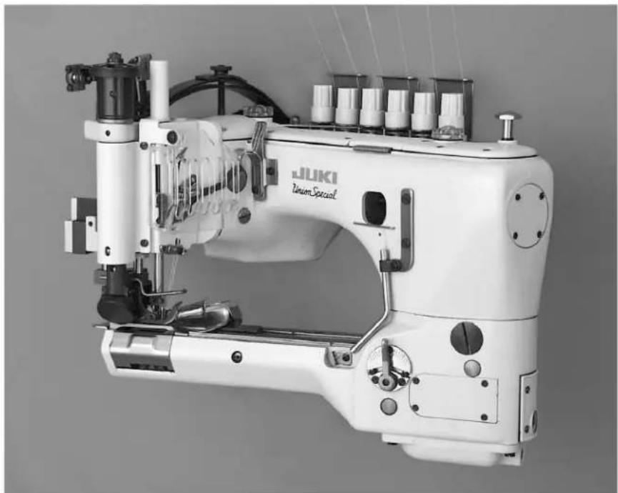
Black-and-white photo of a JUKI Union Special sewing machine (no visible text or symbols on the device body)MANUAL NO. EN9917
FOR PNEUMATIC KIT
29480AZP
PNEUMATIC KIT 29480AZP
This Engineer's Manual has been designed to assist you in the disassembly, reassembling and adjusting of pneumatic kit 29480AZP for the Union Special 35800 class machines.
It is the desire of Union Special Corporation that each machine run at its optimum performance. Procedures in this manual are designed specifically for the class 35800 machines and are written to assure long lasting service.
This manual has been comprised on the basis of available information at the time of printing. Changes in design and/or improvements may incorporate a slight modification or configuration in illustrations or adjustments.
This manual should be used in conjunction with PT9804.
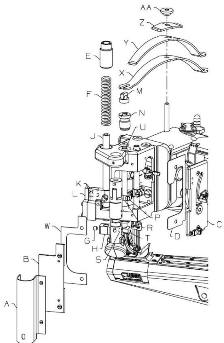
FIG. 1
REMOVE:
- Remove Cover (A, Fig 1).
- Remove Cover (B, Fig 1).
- Remove Gasket (W, Fig 1).
- Remove Front Head Cover (C, Fig 1).
- Remove Gasket (D, Fig 1).
- Remove Puller Bar Knob (E, Fig 1).
- Remove Puller Bar Spring (F, Fig 1).
- Loosen Puller Bar Clamp Screw (G, Fig 1) in Puller Assembly (H, Fig 1).
- Loosen Two Puller Bar Clamp Screws (K, Fig 1) In Rear Guide Finger (L, Fig 1).
- Lift Roller Bar (J, Fig 1) And Remove Puller Assembly (H, Fig 1) From Bar.
- Remove Roller Bar (J, Fig 1).
- Remove Presser Regulating Nut (AA, Fig 1).
- Remove Presser Spring Plate (Z, Fig 1).
- Remove Presser Spring Upper (Y, Fig 1).
- Remove Presser Spring Lower (X, Fig 1).
- Remove Presser Bar Knob (M, Fig 1).
- Remove Presser Bar Spring And Regulator (N, Fig 1).
- Loosen Clamp Screw (P, Fig 1) In Presser Bar Lifter And Guide (R, Fig 1).
- Loosen Presser Foot Clamp Screw (S, Fig 1) In Presser Foot Fork (T, Fig 1).
- Remove Presser Bar (U, Fig 1).
ADD/ADJUST:
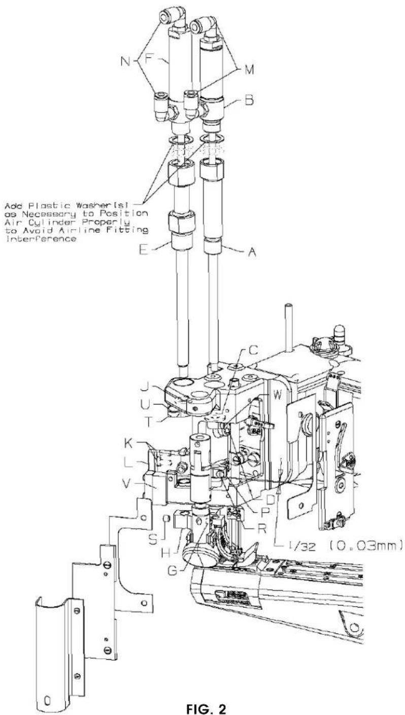
- Screw Cylinder Adaptor (A, Fig 2) For Presser Bar Into Head.
- Slide Presser Bar Air Assembly (B, Fig 2) Into Adaptor (A, Fig 2).
- To Presser Bar Add Neoprene Washer (C, Fig 2) And Clamp Collar (D, Fig 2).
- Presser Bar Should Then Go Into Presser Bar Lift Clamp (P, Fig 2).
- Screw Air Cylinder Into Adaptor (A, Fig 2).
- Attach Presser Foot Fork To Presser Bar. Tighten Screw (G, Fig 2) In Fork Against Flat On Bar.
- Align Needle Holes Of Presser Foot With Needle Holes In Throat Plate. With Feed Dogs Below Throat Plate Make Sure Presser Foot Is Resting On Throat Plate, Position Presser Bar Lift Clamp About 1/32" (0.3mm) Above Top Of Presser Bar Bushing And Tighten Clamp Screw (R, Fig 2).
- Set Collar (D, Fig 2) To Stop Against Casting So That When Needles Are Down And Foot Is Lifted The Bottom Of The Needle Head And Top Of Presser Foot Have Clearance. Tighten Screw (W, Fig 2).
* See Note On Adding Plastic Washer(s), If Necessary Repeat Above Disassembly & Assembly. - Screw Cylinder Adaptor (E, Fig 2) For Puller Bar Into Casting.
- Slide Puller Shaft Air Cylinder Assembly (F, Fig 2) Into Adaptor (E, Fig 2).
- To Puller Shaft Add Neoprene Washer (J, Fig 2) And Clamp Collar (T, Fig 2).
- Puller Bar Should Then Go Into Rear Guide Finger (L, Fig 2) And Then Go Into Bottom Bushing Of Bed.
- Screw Air Cylinder Into Air Cylinder Adaptor (E, Fig 2).
- Attach Puller Assembly (H, Fig 2) To Puller Bar. Puller Bar Should Go Into Puller Yoke As Far As Possible, Tighten Clamp Screw (S, Fig 2) Against Flat On Bar.
* See Note On Adding Plastic Washer(s), If Necessary Repeat Above Disassembly & Assembly. - Using Shim(s) Adjust Feed Roller Mechanism (H, Fig 2) So That The Roller Is .003" (0.08mm) To .005" (0.13mm) Above Throat Plate. Slide Rear Guide Finger (L, Fig 2) Down So That It Sits On Top Of Rear Guide Support Block (V, Fig 2). Guide Finger For Roller Should Be Set So That Entire Roller Mechanism Has Free Movement Up And Down With No Left To Right Movement. With Roller Properly Aligned, The Edge Of The Roller Should Be Parallel With Feed Slots In Throat Plate. Tighten Two Screws (K, Fig 2) To Secure Feed Roller Mechanism In Place.
- Set Stop Collar (K, Fig 2) So That When Puller Assembly Is Lifted There Is Clearance Between Roller And Bottom Of Presser Foot Fork. Tighten Screw (U, Fig 2).
- Reassemble Gaskets And Covers To The Machine.
- Assemble (2) Air Fittings (M, Fig 2) Into Air Cylinder (B) For Presser Bar.
- Assemble (2) Air Fittings (N, Fig 2) Into Air Cylinder (F) For Roller Bar.
ADD/ADJUST(CONT.):
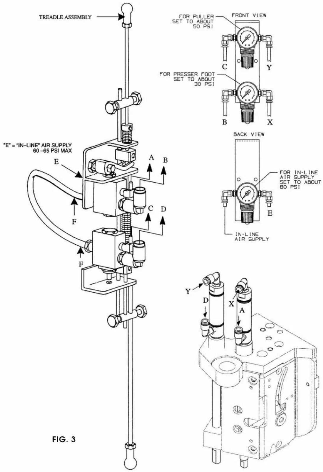
- Mount Treadle Switch Assembly (X, Fig 3) To Pedestal As Per Instructions Included With Kit.
- Assemble Air Regulators And Mount To Pedestal.
- Attach Air Lines As Per (Fig 3).
- Set Air Regulator To Recommended P.S.I. As Per (Fig 3). The Pressure For The Puller And / Or Presser Foot May Have To Be Adjusted To Suit Proper Sewing Condition.
- The Treadle Switch May Have To Be Adjusted To Suit Operators Preference. Sequence Should Be: Slight Heal Pressure On Treadle Should Lift Presser Foot Only, Further Healing Should Lift Roller. Both Presser Foot And Roller Should Stay In Up Position As Long As Maximum Healing Of Treadle Is Applied. Both Presser Foot And Roller Should Be In Down Position Before Sewing Begins.
Union Special Corporation
Corporate Office
One Union Special Plaza
Huntley, IL 60142
Phone: 847·669·5101
Fax: 847·669·4454
Union Special GmbH
EuropeanDistributionCenter
Raiffeisenstrasse 3
D-71696 Möglingen, Germany
Tel: 49·07141·247·0
Fax: 49·07141·247·100
JUKI CORPORATION
INTERNATIONAL SALES DIVISION
8-2-1, KOKURYO - CHO,
CHOFU-SHI, TOKYO 182, JAPAN
PHONE: 03(3430)4001\~5
FAX: 03(3430)4909.4914.4984

Finest Quality
Union Special INDUSTRIAL SEWING EQUIPMENT
Mærke : Union Special
Model : 29480AZP
Kategori : Symaskine