
SV12170 - Batteri Sven - Gratis brugsanvisning og manual
Find enhedens vejledning gratis SV12170 Sven i PDF-format.

Brugerspørgsmål om SV12170 Sven
0 spørgsmål om dette apparat. Besvar dem du kender, eller stil dit eget.
Stil et nyt spørgsmål om dette apparat
Download vejledningen til din Batteri i PDF-format gratis! Find din vejledning SV12170 - Sven og tag din elektroniske enhed tilbage i hånden. På denne side er alle dokumenter nødvendige for brugen af din enhed offentliggjort. SV12170 af mærket Sven.
BRUGSANVISNING SV12170 Sven
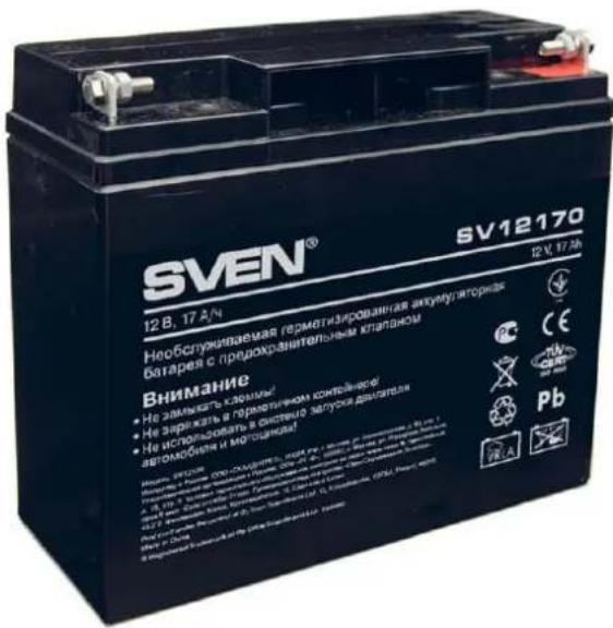
SV12170
text_image
SVEN® 12 B, 17 A/N 12 V, 17 A/N Нообслуживаемая герматизированная аккумуляторная батарея с предохранительным клапиком Внимание • Не замлявать клапикы! • Не заряжать в герметичном контейнерг. • Не использовать в скотечное загулиса двигателя автомобели и мотечника! Начал: 3520% Разначение ОПО-ОКЛАЙТЕЯ: 1984 РГ / кммх, по тел. 2016 г. 10000000000000000000000000000000000000000000000000000000000000 СЕ РНУ РМ РБ РЗА РЗАFEATURES
■ AGM maintenance-free lead-acid battery
■ High-efficiency lead-calcium plates
■ Construction of fiber-glass separators stabilizes temperature of electrolyte
■ High-quality insulation of plates
■ Safe system of internal pressure regulating valves
■ Reduced self-discharge current
■ Sealed construction
■ Long cycle life both in float and cycle charge modes
■ Quality of products is guaranteed by the control of the manufacturing process in accordance with the standards
SPECIFICATION
| Nominal Voltage | 12 V |
| Nominal Capacity | 17 A·h at 20Hr-rate to 1.75V/cell |
| Approx. Weight | 5.0 Kg |
| Number of cells in battery | 6 |
| Internal Resistance | 15 mΩ (Fully Charged) at 25 °C |
| Self-Discharge | Average 3% of capacity declined per month at 25 °C |
| Operating Temp. Range | Discharge: -20 °C ~ 50 °CCharge: -15 °C ~ 40 °CStorage: -20 °C ~ 40 °C |
| Max. Discharge Current | 225 A (5 sec.) |
| Capacity Affected by Temp. | 40 °C 102%25 °C 100%0 °C 85%-15 °C 65% |
| Container Material | ABS plastic |
APPLICATION
All Purpose
UPS
Signal Light
Alarm and Security System
DC Power Supply
Auto Control System
APPLICABLE STANDARDS
IEC61056-1/2
JIS C8702-2003
GB/T19639.1-2005

CHARGE PROCEDURE DISCHARGE CURRENT VS. DISCHARGE VOLTAGE
| Application | Constant Voltage Charge (V/cell) | Max. Charge Current | ||
| Temperature | Set Point Allowable Range | |||
| Cycle Use | 25°C | 2.425 | 2.40~2.45 | 0.3C |
| Standby Use | 25°C | 2.275 | 2.25~2.30 | |
| Final Discharge Voltage (V/cell) | 1.75 1.70 | 1.60 | |
| Discharge Current (A) | 0.2C>(A) 0.2C<(A)<1C (A)>1C | ||
Note: Temp. Compensation Coefficient of Charge Voltage,
Cycle use: -4mV/°C/cell, Standby Use: -3 mV/°C/cell
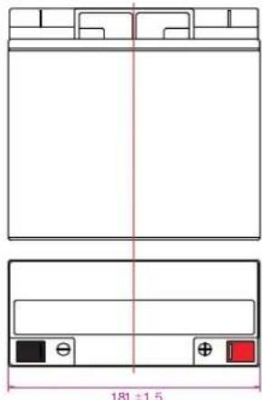
OUTER DIMENSION
■ Length 181 ± 1.5
Width 77 ± 1.5
■ Height 160.5 ± 2.0
■ Total height 167 ± 2.0
Unit: mm
text_image
181 ±1.5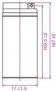
text_image
77 ±1.5 160.5 ±2 167 ±2Terminal T1
TerminalType
Terminal B1
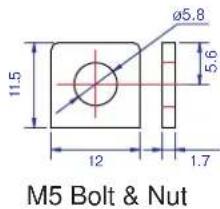
text_image
M5 Bolt & Nut 11.5 12 ø5.8 5.6 1.7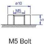
Discharge Characteristics at 25 °C
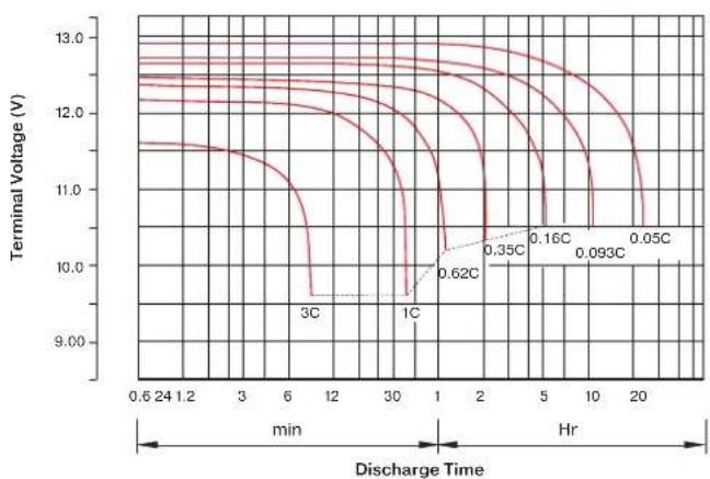
line
| Discharge Time | Terminal Voltage (V) | | -------------- | -------------------- | | 0.6 | 11.5 | | 1.2 | 11.4 | | 3 | 11.3 | | 6 | 11.0 | | 12 | 10.5 | | 30 | 10.0 | | 6 | 9.8 | | 1 | 9.7 | | 2 | 9.6 | | 5 | 9.5 | | 10 | 9.4 | | 20 | 9.3 |Charge Characteristics (Standby Use)
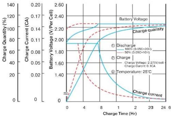
line
| Charge Time (Hr) | Charge Quantity (%) | Battery Voltage (V/Per Cell) | | ---------------- | ------------------- | ---------------------------- | | 0 | 0 | 0 | | 4 | ~1.8 | ~1.4 | | 8 | ~2.0 | ~1.6 | | 12 | ~2.2 | ~1.8 | | 16 | ~2.25 | ~2.0 | | 20 | ~2.3 | ~2.2 | | 24 | ~2.3 | ~2.2 |Capacity Retention Characteristics
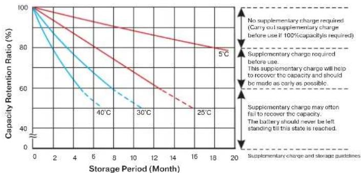
line
| Storage Period (Month) | No supplementary charge required (Carry out supplementary charge before use if 100% capacity is required) | Supplementary charge required before use. This supplementary charge will help to recover the capacity and should be made as early as possible. | Supplementary charge may often fail to recover the capacity. The battery should never be left standing till this state is reached. | | ---------------------- | ---------------------------------------------------------------------------------- | ---------------------------------------------------------------------------------- | ---------------------------------------------------------------------------------- | | 0 | 100 | 100 | 100 | | 2 | ~98 | ~98 | ~98 | | 4 | ~96 | ~96 | ~96 | | 6 | ~94 | ~94 | ~94 | | 8 | ~92 | ~92 | ~92 | | 10 | ~90 | ~90 | ~90 | | 12 | ~88 | ~88 | ~88 | | 14 | ~86 | ~86 | ~86 | | 16 | ~84 | ~84 | ~84 | | 18 | ~82 | ~82 | ~82 | | 20 | ~80 | ~80 | ~80 |Cycle Service Life
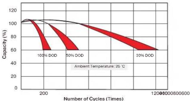
line
| Number of Cycles (Times) | Capacity (%) | | ------------------------ | ------------ | | 200 | 100 | | 50 | 60 | | 1200 | 60 |Constant Current (CC, Unit: A) & Constant Power (CP, Unit: W) Discharge Table at 25 °C
| F.V.(V/cell) | TimeModel | 5 Min | 10 Min | 15 Min | 30 Min | 1 Hr | 2 Hr | 3 Hr | 4 Hr | 5 Hr | 8 Hr | 10 Hr | 20 Hr |
| 1.60 | CC(A) | 61.2 | 40.1 | 29.8 | 19.6 | 10.2 | 5.95 | 4.38 | 3.51 | 2.98 | 1.97 | 1.61 | 0.88 |
| CP(W) | 722 | 453 | 343 | 208 | 118 | 68.9 | 50.65 | 40.66 | 34.50 | 22.74 | 18.63 | 10.20 | |
| 1.70 | CC(A) | 56.1 | 38.4 | 27.3 | 18.6 | 9.6 | 5.71 | 4.25 | 3.40 | 2.93 | 1.93 | 1.58 | 0.86 |
| CP(W) | 679 | 429 | 322 | 206 | 111 | 66.1 | 49.23 | 39.38 | 33.86 | 22.38 | 18.28 | 9.92 | |
| 1.75 | CC(A) | 51.1 | 35.9 | 25.5 | 18.0 | 9.3 | 5.60 | 4.18 | 3.23 | 2.91 | 1.91 | 1.56 | 0.85 |
| CP(W) | 656 | 417 | 308 | 204 | 107 | 64.8 | 48.38 | 37.40 | 33.65 | 22.17 | 18.13 | 9.85 | |
| 1.80 | CC(A) | 49.1 | 34.3 | 23.8 | 17.5 | 9.0 | 5.45 | 4.11 | 3.17 | 2.76 | 1.86 | 1.52 | 0.83 |
| CP(W) | 575 | 404 | 297 | 203 | 104 | 63.5 | 47.81 | 36.94 | 32.16 | 21.25 | 17.71 | 9.63 | |
| 1.85 | CC(A) | 45.4 | 32.3 | 22.1 | 17.0 | 8.6 | 5.31 | 3.90 | 3.12 | 2.64 | 1.81 | 1.49 | 0.81 |
| CP(W) | 556 | 390 | 283 | 202 | 103 | 63.0 | 46.40 | 36.83 | 31.45 | 20.54 | 17.35 | 9.56 |
Note: The above data are average values, and can be obtained with 3 charge/discharge cycles.