VCR - Detektor Vemer - Gratis brugsanvisning og manual
Find enhedens vejledning gratis VCR Vemer i PDF-format.

Brugerspørgsmål om VCR Vemer
0 spørgsmål om dette apparat. Besvar dem du kender, eller stil dit eget.
Stil et nyt spørgsmål om dette apparat
Download vejledningen til din Detektor i PDF-format gratis! Find din vejledning VCR - Vemer og tag din elektroniske enhed tilbage i hånden. På denne side er alle dokumenter nødvendige for brugen af din enhed offentliggjort. VCR af mærket Vemer.
BRUGSANVISNING VCR Vemer
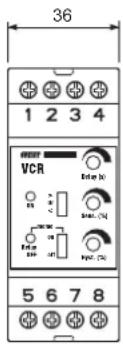
Dimension
text_image
36 1 2 3 4 VCR Enter (b) Enter (c) Enter (d) Enter (e) Enter (f) Enter (g) Enter (h) Enter (i) Enter (j) Enter (k) Enter (l) Enter (m) Enter (n) Enter (o) Enter (p) Enter (q) Enter (r) Enter (s) Enter (t) Enter (u) Enter (v) Enter (w) Enter (x) Enter (y) Enter (z) Enter (w) 5 6 7 8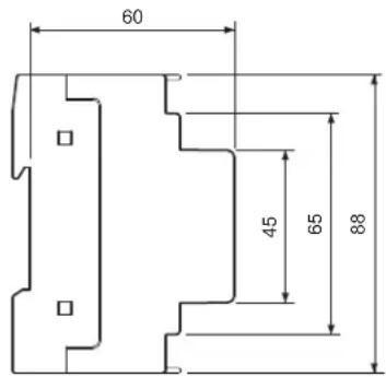
text_image
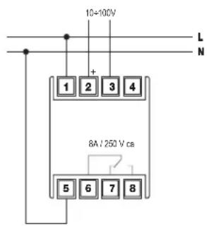
60 45 65 88Connection diagram
text_image
10+100V L N + 1 2 3 4 8A / 250 V ca 5 6 7 8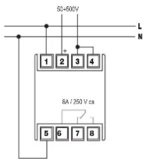
text_image
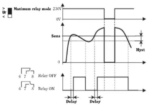
50-500V L N 1 2 3 4 8A / 250 V cm 5 6 7 8Operating diagram
line
| Signal | Value | |--------|-------| | Maximum relay mode | 230V | | Sens | 0V | | Hyst | 0V |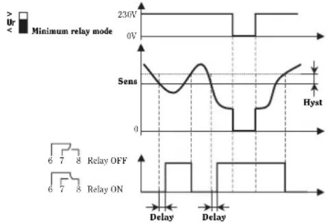
line
| Parameter | Value | | ----------------- | ----- | | Ur | 230V | | Minimum relay mode | 0V | | Sens | 0 | | Delay | High | | Relay OFF | Low | | Relay ON | Low |Voltage control relay VCR is an electronic control device to be mounted on a panel in a standard 2-DIN size enclosure. It operates an external circuit following the tripping setting (direct or alternate voltage): threshold values, hysteresis and change-over delay can be adjusted.
SAFETY INSTRUCTIONS
During the installation and operation of the device observe the following instructions:
1) The device must be installed by a qualified person, strictly following the wiring diagrams.
2) The device must be installed in an electrical panel which, after installation, leaves terminals inaccessible.
3) Do not power or connect the device if any part of it is damaged.
4) The electrical system in the building where the device is installed must feature a circuit breaker and an overcurrent protection device.
5) The device is aimed for use in places with over-voltage category III and pollution degree, 2 as per standards EN 61010-1.
Code Model Description
VE144200 VCR
Voltage-control relay
TECHNICAL SPECIFICATIONS
• Power supply: 230 V CA (-15% ÷ +10%), 50/60 Hz
• Consumption: ≤ 4VA
• Termination: 6 mm ^2 metal blocks
• Output: changeover contact relay 8 A / 250 V AC (resistive load)
- Input signal
- 10 V ÷ 100 V
- 50 V ÷ 500 V
• Full scale selection by wiring (cfr. Connection diagram)
• Threshold: to be trimmer-adjusted between 10% and 100% of the full scale value
• Hysteresis: to be trimmer-adjusted between 5% and 50% of the threshold value
- Relay switching delay: to be trimmer-adjusted from 0,1 to 10 seconds
• Signalling by 2 LEDs
- green = power on
- red = relay off (alarm)
• Operating temperature: -5^ ÷ +50^
• Storage temperature: -10^ ÷ +70^
• Input impedance: 2 M Ω
• Enclosure: 2 DIN size
- Setting of maximum or minimum relay by selector
- Setting of alarm status memory by way of selector
• Degree of protection: IP20/IP40 when correctly installed in an electrical panel
WIRING
• Power the device up by connecting terminal 1 to line and terminal 5 to neutral.
- Connect the signal to the measuring terminals according to range (for use with DC also observe polarity);
- 10V÷ 100V between terminals 2 and 3
50 V ÷ 500 V between terminals 2 and 3, after terminals 3 and 4 have been short-circuited
OPERATION
- Select maximum or minimum relay mode using the selector on the front of the device (>Ur → maximum relay, <Ur → minimum relay)
- Select threshold voltage using trimmer Sens
Select hysteresis value using trimmer Hyst - Select the delay value using the Delay trimmer. This is the time intervening between the moment Ur is exceeded and the moment the relay switches over
- Selector memo enables the memory storing function. After alarm and the consequent relay switch over, the memory function keeps the acquired output status even when the measured value is back in the useful range; memory is zeroed using the selector, so that the device does not need to be switched off
RIFERENCE STANDARDS
Conformity to the EU directives:
2006/95/EC (Low Voltage)
89/336/EEC modified by 92/31/EEC and 93/68/EEC (EMC)
is declared with reference to the following harmonised standards:
Safety: EN 61010-1
Electromagnetic compatibility: EN 61000-6-2, EN 61000-6-4