Energy-3x130 PWR - Måling Vemer - Gratis brugsanvisning og manual
Find enhedens vejledning gratis Energy-3x130 PWR Vemer i PDF-format.

Brugerspørgsmål om Energy-3x130 PWR Vemer
0 spørgsmål om dette apparat. Besvar dem du kender, eller stil dit eget.
Stil et nyt spørgsmål om dette apparat
Download vejledningen til din Måling i PDF-format gratis! Find din vejledning Energy-3x130 PWR - Vemer og tag din elektroniske enhed tilbage i hånden. På denne side er alle dokumenter nødvendige for brugen af din enhed offentliggjort. Energy-3x130 PWR af mærket Vemer.
BRUGSANVISNING Energy-3x130 PWR Vemer
V3IS00244-100_02-2013

Vemer S.p.A.
I - 32032 Feltre (BL) • Via Camp Lonc, 16
Tel +39 0439 80638 • Fax +39 0439 80619
e-mail: info@vemer.it - web site: www.vemer.it
Mod. ENERGY-400 PWR ENERGY-3x130 PWR ENERGY-3x130 PWRI

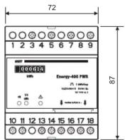
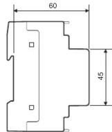
Dimensions (A)
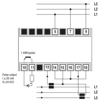
Connection diagrams (B)
3 CT connection WITH or WITHOUT neutral (3 or 4 wires)
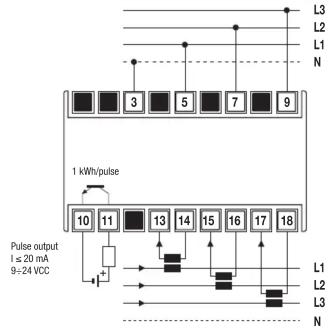
flowchart
graph TD
    A["Component 10"] --> B["Component 11"]
    B --> C["Component 13"]
    C --> D["Component 14"]
    D --> E["Component 15"]
    E --> F["Component 16"]
    F --> G["Component 17"]
    G --> H["Component 18"]
    I["L1"] --> J["Input"]
    K["L2"] --> L["Input"]
    M["L3"] --> N["Input"]
    O["N"] --> P["N"]
    Q["Pulse output\nI ≤ 20 mA\n9-24 VCC"] --> R["Resistor"]
    S["1 kWh/pulse"] --> T["Ground"]
2 CT connection (PWRi only) WITHOUT neutral (3 wires)
User Manual
ACTIVE ENERGY METER

Read all the instructions carefully
The ENERGY-400 and ENERGY-3x130 are electronic static devices to read active energy in three-phase systems designed to operate in environments with measurement category III and pollution level 2 according to EN 61010-1 standard.
SAFETY WARNINGS
To guarantee correct installation, proceed as follows:
1) The appliance should be installed by a qualified operator
2) The appliance should be installed in a panel in such a way as to guarantee that the
terminals are inaccessible after fitting
3) A protection device against over-currents should be installed in the electrical system,
upstream of the energy meter
4) Connect the instrument as shown in the alongside diagrams
5) Before touching the connector terminals make sure that the wires to be connected or
already connected to the instrument are not live
6) Touch the dip-switches only when the instrument is not powered
7) Do not power or connect the instrument if any part of it is damaged
8) The instrument must be installed and activated in compliance with current electric
system standards.
Code Model Description
VN964300 ENERGY-400 PWR Three-phase energy meter 400 V AC
VN966800 ENERGY-3x130 PWR Three-phase energy meter 3x130 V AC
VN967600 ENERGY-3x130 PWRi Three-phase energy meter 3x130 VAC
TECHNICAL SPECIFICATIONS
• Power supply:
3x230 V AC phase-neutral (400VAC phase-phase) (-15% ÷ +10%)
for Energy-400 model
- 3x130 V AC phase-neutral (230VAC phase-phase) (-15% ÷ +10%)
for Energy-3x130 models
• Frequency: 50/60 Hz
• Rated current: 5 A
• Maximum current: 6 A
• Minimum start-up current: 15 mA
• Maximum power consumption:
- voltage circuits < 2.5 VA
- current circuits < 2.5 VA
• Meter constant: 1 imp = ¼ kWh
• Voltage inputs: input impedance = 2 MΩ
• Current inputs:
- shunt of 0.022Ω (+/-10%) for PWR models
coils with galvanic insulation between primary and secondary for Energy-3x130 PWRi
mode
• Two optic insulated impulse output:
- impulse duration < 100 ms
- voltage 9÷24 V DC
- current < 20 mA
• Insulation:
- reinforced between impulse output and other terminals
- reinforced between terminals and parts accessible after installation
• CT available: 5-10-25-50-75-100-125-150-200-250-300-400-500-600-800 1000/5 A
• Operating temperature: -10 °C ÷ +45 °C
• Storage temperature: -25°C ÷ + 70 °C
• Relative humidity: 10÷90% non condensing
• Class index: class A (FN 50470)
• Container: 4 module DIN
• Protection level: IP20 / IP40 on the front
Instrument description (C)
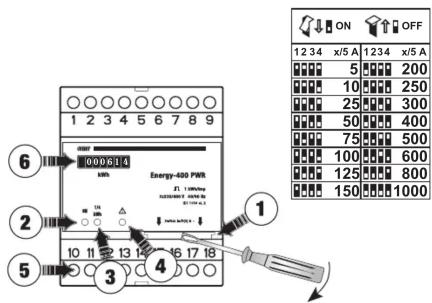
INSTRUMENT DESCRIPTION
① Dip-switch for CT setting
② Green warning light: lights up to indicate power on
③ Red warning light: flashes to indicate that the instrument is metering energy
(1 flash=¼ kWh)
④ Yellow warning light: when lit the instrument detects 1/4 kWh negative (probable
incorrect entry) and remains lit until 14 kWh positive is detected
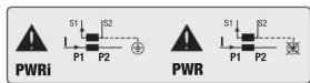
Check the insertion of CT: connect L1, L2, L3 from power panel to P1 of CT and
connect P2 of CT to the load.
⑤ Impulse output: Optically insulated
⑥ Electro-mechanical impulse counter: resolution 1 kWh
GUIDE TO INSTALLATION
1) Before installing the instrument, select the required transformation ratio, as shown in panel C)
2) For Energy-3x130 PWRi model only, the CT secondaries may be connected to earth
3) The instrument should be connected as shown in the panel B), in accordance with the CT current directions
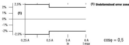
4) If the error is to fall within the class limits of the instrument, it is necessary to use the current transformer in its linear operating field.
line
| x | y | |-------|--------| | 0.25 A| 2.5% | | 0.5 A | 2.5% | | 0.5 A | -2.5% | | 6 A | 2.5% |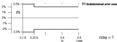
line
(1) Undetermined error zone | Time (s) | Value (%) | | :--- | :--- | | 0.1 A | -2.5 | | 0.25 A | -2.5 | | 5 A In | 2.5 | | 6 A I max | 2.5 | COSφ = 15) If the instrument is active the power should be switched off to change the CT ratio.
6) In case of changes to the dip-switch with the instrument activated, these locks in fault condition with red and green lights always on. In this condition the instrument doesn't coun.
To restore the correct operation, reposition the DIP switches in the initial condition or reset the instrument by removing and restoring power.
REFERENCE STANDARDS
Conformity to EU directive:
2004/22/EC (MID)
2006/95/EC (Low Voltage - LVD)
is declared with reference to the following harmonised standards:
EN 61010-1
EN 50470-1 and EN 50470-3
Mærke : Vemer
Model : Energy-3x130 PWR
Kategori : Måling