TIMM - R cap - Termostat Vemer - Gratis brugsanvisning og manual
Find enhedens vejledning gratis TIMM - R cap Vemer i PDF-format.

Brugerspørgsmål om TIMM - R cap Vemer
0 spørgsmål om dette apparat. Besvar dem du kender, eller stil dit eget.
Stil et nyt spørgsmål om dette apparat
Download vejledningen til din Termostat i PDF-format gratis! Find din vejledning TIMM - R cap - Vemer og tag din elektroniske enhed tilbage i hånden. På denne side er alle dokumenter nødvendige for brugen af din enhed offentliggjort. TIMM - R cap af mærket Vemer.
BRUGSANVISNING TIMM - R cap Vemer
ISCOM032-2106

Vemer S.p.A.
I - 32032 Feltre (BL) • Via Camp Lonc, 16
e-mail: info@vemer.it - web site: www.vemer.i
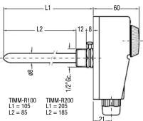
Mod. TIMM - R100
TIMM - R200
TIMM - R can
TIMM Roup TIMM P
TREM - B
TIMM - RB
User Manual
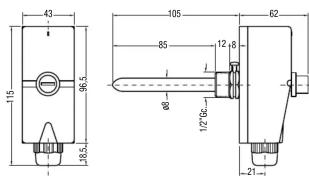
ADJUSTABLE THERMOSTAT – IMMERSION – WITH SHANK
Read all the instructions carefully
■ TIMM – R100 and TIMM – R200 are boxed unipolar thermostats, liquid expansion, with switching
contacts, complete with core hitch. Ideal for automatic regulation on boilers, pumps and other heating
equipment. The thermolots are fixed using a 1/2" threaded iron
SAFETY WARNINGS
CHECK THAT THE POWER IS DISCONNECTED on the USER BEING CONTROLLED before connecting the
thermostat. Check that the power input is compatible with the output on the contacts (see the
technical data).
Model
The Ground Truth image displays a single, solid horizontal line. According to Rule 2 (UNDERSCORE & LINE RULES), if the GT contains lines used for stylistic emphasis or as background elements (like a ruled line), the OCR result must ignore them. The provided OCR content is "____", which consists of four underscores. This is an incorrect interpretation of the line as a placeholder symbol, violating the rule that stylistic lines must be ignored. Therefore, the OCR output hallucinated symbols where none should exist. Hence, the result is inconsistent with the Ground Truth.
C 1200m
Description
0/90°C L100mm
VE306700 TIMM - R200 Adjustable thermostat 30/90°C L200mm
The Ground Truth image displays a single, continuous horizontal line, which is a stylistic or background element (like a ruled paper line or separator), not a placeholder for text. According to Rule 2, such stylistic/background lines must be ignored by the OCR result. The OCR content provided is "", which consists of no characters. This correctly represents the line in the GT by ignoring it entirely. Since the OCR output includes underscores for a stylistic line, this complies with Rule 2. Therefore, the OCR result is consistent with the Ground Truth.
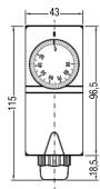
Dimensions
TECHNICAL DATA
- Setting range: +30 ÷ +90°C (±3°C)
• Differential: 4°C ±2°C
- Degree of protection: IP 40 - Insulation class: II
- Insulation class. - Thermal gradient
• Maximum head temperature: 80°C
• Maximum bulb temperature: 110°C
• Maximum sheath pressure: 10 bar
• Change-over contacts
- Contact outputs: 16 A (5) 250 Vca
• Action type: TB • Care history: M20
• Core Hlth. M20
INSTALLATION
- ATTENTION: only specialised electricians or authorised installers must carry out the instructions given in this leaflet, in full observance of the safety instructions and current applicable legislation.
CONNECTIONS
A. Loosen the screw to remove the trap from the instrument.
B. Fix the trap in the correct housing ( 12 " threading).
C. Replace the bulb on the thermostat inside the trap and tighten down the fixing screw D. Slide off the knob and upscrew the two screws beneath to open the thermostat cover
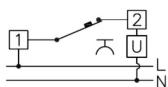
B. Glade on the knob and discrew the two screws button to open the thermostat cover. E. Pass the leads through the core hitch and make the connections following the diagram below.
■ Use the loads through the bore filter and make the connotations following the diagram below.

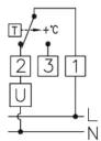
Terminal 1 = common
Terminal 2 = opens the
set temperature is reached
Terminal 3 = closes the circuit when the
set temperature is reached
F. Replace the cover, screws and knob.
REFERENCE STANDARDS
Conformity to the EU directive 2014/35/UE (LVD) and 2014/30/UE (EMCD)
is declared in reference to the harmonised standards: EN 60730-1, EN 60730-2-9
User Manual
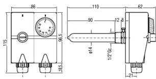
ADJUSTABLE THERMOSTAT - WITH EXTERNAL CAPILLARY
Read all the instructions carefully
- TIMM – R can is a boxed uninolar thermostat, liquid expansion, with switching contacts, complete with core
- Hinch. Ideal for automatic regulation on boilers, pumps and other heating equipment.
The thermostat can be fixed on any surface using the perforated fins.
m = 311
SAFETY WARNINGS
CHECK THAT THE POWER IS DISCONNECTED on the USER BEING CONTROLLED before connecting the
thermostat. Check that the power input is compatible with the output on the contacts (see the technical
data)
Model
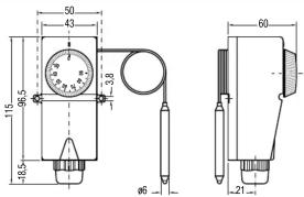
TIMM - R cap
Description
Adjustable thermostat 30/90°C with extern capillary L1000mm
Dimensions
TECHNICAL DATA
- Setting range: + 30 ÷ + 90^ C( +3^ C)
• Differential: 4^ C ±2°
• Degree of protection: IP 40
• Insulation class: II
• Thermal gradient: <1
• Maximum head temperature: 80°C • Maximum bulb temperature: 110°C
• Maximum build temp • Change-over contacts - Contact outputs: 16 A (5) 250 Vca
• Action type: 1B - Core hitch: M20
INSTALLATION
- ATTENTION: only specialised electricians or authorised installers must carry out the instructions given in this leaflet, in full observance of the safety instructions and current applicable legislation.
CONNECTIONS
A. Fix on any surface using the perforated fins.
B. Immersive the bulb at the end of the capillary in the liquid (or place it closely touching the surface) that the temperature has to be regulated for
temperature has to be regulated for
C. Slide on the knob and discrew the two screws beneath to open the thermostat cover. D. Pass the leads through the core hitch and make the connections following the diagram below.
E. Replace the cover, screws and knob.
REFERENCE STANDARDS
Conformity to the EU directive 2014/35/UE (LVD) and 2014/30/UE (EMCD) is declared in reference to the harmonised standards: EN 60730-1, EN 60730-2-9
User Manual
RESETTABLE THERMOSTAT - IMMERSION - WITH SHANK
Read all the instructions carefully
- TIMM – B is a boxed unipolar thermostat, liquid expansion, complete with core hitch. Temperature safety control with manual reset and positive security. The thermostat is fixed using a 12 " threaded trap.
SAFETY WARNINGS
CHECK THAT THE POWER IS DISCONNECTED on the USER BEING CONTROLLED before connecting the thermostat. Check that the power input is compatible with the output on the contacts (see the technical data).
•
Model
Description
Resettable thermostat L100mm
Dimensions
TECHNICAL DATA
- Limiter pre-set temperature: 99^(± 4^)
- Reset manual and positive s
• Degree of protection: IP 40
• Insulation class: II - Thermal gradient: < 1^ C/min - Maximum head temperature:
• Maximum bulb temperature: 110°C
• Maximum bolt temperature: 110°C • Maximum sheath pressure: 10 bar
• Normally closed contact - Contact outputs: 16 A (5) 250 Vca
• Action type: 1B
- Core hitch: M20
INSTALLATION
- ATTENTION: only specialised electricians or authorised installers must carry out the instructions given in this leaflet, in full observance of the safety instructions and current applicable legislation.
CONNECTIONS
A. Loosen the screw to remove the trap from the instrument. B. First time in the work of (50000000).
B. Fix the trap in the correct housing ( 12 -threading). C. Replace the bulb on the thermostat inside the top and tighten down the fixing screw.
c. Replace the bulb on the thermostat inside the trap and tighten down the fixing screw. D. Uncrew the protection hood of the receptable push-button and the below dice to open the thermostat
D. Onshore cover
E. Pass the leads through the core hitch and make the connections following the diagram below.
Terminal 1 = common
Terminal 2 = opens the
terminal 2 opens the circuit when the set temperature is reached
(99°C +4°C)
F. Replace the cover, nut and gap.
RESET OPERATION
In case of activation of the reset thermostat (open contact), wait until the system temperature falls within the normal limits. Remove the causes that led to the overheating of the system. Then proceed to manually reset the thermostat by removing the plastic cap and pushing the button inside the nut with a special tool. Finally screw the cap onto the nut.
REFERENCE STANDARDS
Conformity to the EU directive 2014/35/UE (LVD) and 2014/30/UE (EMCD) is declared in reference to the harmonised standards: EN 60730-1, EN 60730-2-9
User Manual
DOUBLE RESETTABLE AND ADJUSTABLE THERMOSTAT - IMMERSION - WITH SHANK
Read all the instructions carefully
TIMM – RB is a boxed double unipolar thermostat, liquid expansion, with switching contacts, complete with core hitches. Temperature regulator and safety control with manual reset and positive security. The thermostat is fixed using a 12 " threaded trap.
SAFETY WARNINGS
CHECK THAT THE POWER IS DISCONNECTED on the USER BEING CONTROLLED before connecting the thermostat. Check that the power input is compatible with the output on the contacts (see the technical data).
Code
Model
TIMM-RB Resettable and adjustable thermostat 30/90°C L100mm
Dimensions
TECHNICAL DATA
- Regulator temperature setting range: +30 ÷ +90°C (± 3°C)
• Differential: 4^ ± 2^
- Limiter pre-set temperature: +99°C (± 4°C) - Reset: manual and positive safety
• Degree of protection: IP40
• Insulation class: II
• Thermal gradient: <1 °C/min
• Maximum head temperature: 80°C
• Maximum bulb temperature: 110°C • Maximum sheath pressure: 10 bar
• Maximum sheath pressure: 10 bar • Normally closed or change-over contacts
- Contact outputs: 16 A (5) 250 Vca
• Action type: 1B
- Core hitch M20
INSTALLATION
- ATTENTION: only specialised electricians or authorised installers must carry out the instructions given in this leaflet, in full observance of the safety instructions and current applicable legislation.
CONNECTIONS
A. Loosen the screw to remove the trap from the instrument.
B. Fix the trap in the correct housing ( 12 " threading). C. Replace the bulbs on the double "thermost" insi
C. Replace the bulbs on the double thermostat inside the trap and tighten down the fixing screw. D. To access to the limites thermostel remove the covers and put. To access to the regulator thermostel
D. to access to the limiter thermostat remove the cover and hot. To access to the I remove the knob and below the screws. Then remove the double plastic cover.
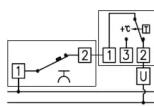
E. Pass the leads through the core hitches. The instrument is designed to work on two independent circuits (one with the regulator and the other with the limiter), or on a single circuit with the regulator and limiter connected as shown in the following diagram.
F. Replace the cover, screws and knob nut and cap
LIMITER
Terminal 1 = common
Terminal 2 = opens the circuit when the set
temperature is reached (99°C +4°C)
REGULATOR
Terminal 1 = common
Terminal 2 = opens the circuit when the
set temperature is reached
Terminal 3 = closes the circuit when the
set temperature is reached
RESET OPERATION
In case of activation of the reset thermostat (open contact), wait until the system temperature falls within the normal limits. Remove the causes that led to the overheating of the system. Then proceed to manually reset the thermostat by removing the plastic cap and pushing the button inside the nut with a special tool. Finally screw the cap onto the nut.
REFERENCE STANDARDS
Conformity to the EU directive 2014/35/UE (LVD) and 2014/30/UE (EMCD)
is declared in reference to the harmonised standards: EN 60730-1, EN 60730-2-9

information to users pursuant to art. 14 of the directive 2012/19 / EU of the european parliament and of the council of 4 July 2012 on waste electrical and electronic equipment (WEEE)
If the crossed-out bin symbol appears on the equipment or packaging, this means the product must not be included with other general waste at the end of its working life. The user must take the worn product to a sorted waste center, or return it to the retailer when purchasing a new one
Products for disposal can be consigned tree or charge (without any new purchase obligation) to retailers with a sales area or at least 400 mZ, if they measure less than 25 cm. An efficient sorted waste collection for the environmentally friendly disposal of the used device, as its subsequent transfers below avoid the potential negative effects on the environment and people's health and encourages the so use and/or sampling of the construction materials.
of its subsequent recycling, helps avoid the potential negative effects on the environment and people's health, and encourages the re-use and/or recycling of the construction materials.
[EMPTY]
[EMPTY]
[Non-Text]
[Non-Text]
[Non-Text]
[Non-Text]
[Non-Text]
[Non-Text]
[Non-Text]
[Non-Text]
[Non-Text]
[Non-Text]
[Non-Text]
[Non-Text]
[Non-Text]
[Non-Text]
[Non-Text]
[Non-Text]
[Non-Text]
[Non-Text]
[Non-Text]
[Non-Text]
[Non-Text]
[Non-Text]
[Non-Text]
[Non-Text]
[Non-Text]
[Non-Text]
[Non-Text]
[Non-Text]
[Non-Text]
[Non-Text]
[Non-Text]
[Non-Text]
[Non-Text]
[Non-Text]
[Non-Text]
[Non-Text]
[Non-Text]
[Non-Text]
[Non-Text]
[Non-Text]
[Non-Text]
[Non-Text]
[Non-Text]
[Non-Text]
[Non-Text]
[Non-Text]
[Non-Text]
[Non-Text]
[Non-Text]
[Non-Text]
[Non-Text]
[Non-Text]
[Non-Text]
[Non-Text]
[Non-Text]
[Non-Text]
[Non-Text]
[Non-Text]
[Non-Text]
[Non-Text]
[Non-Text]
[Non-Text]
[Non-Text]
[Non-Text]
[Non-Text]
[Non-Text]
[Non-Text]
[Non-Text]
Mærke : Vemer
Model : TIMM - R cap
Kategori : Termostat