Commercial MBF8001 - Fryser Atosa - Gratis brugsanvisning og manual
Find enhedens vejledning gratis Commercial MBF8001 Atosa i PDF-format.

Brugerspørgsmål om Commercial MBF8001 Atosa
0 spørgsmål om dette apparat. Besvar dem du kender, eller stil dit eget.
Stil et nyt spørgsmål om dette apparat
Download vejledningen til din Fryser i PDF-format gratis! Find din vejledning Commercial MBF8001 - Atosa og tag din elektroniske enhed tilbage i hånden. På denne side er alle dokumenter nødvendige for brugen af din enhed offentliggjort. Commercial MBF8001 af mærket Atosa.
BRUGSANVISNING Commercial MBF8001 Atosa
INSTRUCTION MANUAL
VERTICAL COOLER
T SERIES REACH-INS
B SERIES REACH-INS
FREEZER: REFRIGERATOR:
| MBF8001 | MBF8002 | MBF8004 | MBF8005 |
| MBF8003 | MBF8007 | MBF8006 | MBF8010 |
| MBF8008 | MBF8009 | MBF8011 | MBF8012 |
| MBF8113 | MBF8114 | MBF8116 | MBF8117 |
| MBF8115 | MBF8118 | ||
| MBF8501 | MBF8502 | MBF8505 | MBF8506 |
| MBF8503 | MBF8504 | MBF8507 | MBF8508 |
Content:
1.Preface....2
2. Use of the equipment....3
3.Technical features....3
4.Operation....3
5.Control unit....4
6. Handling....4
7.Installation procedure....5
8. Connecting to the main power supply....5
9. Maintenance instructions....6
Cleaning....6
Cleaning the refrigerator surface....6
Cleaning the inside of the refrigerator....7
Cleaning the condenser....7
10.Troubleshooting....7
11.Technical service....7
12.Configuration Sketch Map....8
Operating Instruction......8
Electrical Control Circuit Diagram....11
Technical Parameters....13
Official Approval And Rules....14
1. Preface
This instruction manual provides all the necessary information regarding:
▲ use of the refrigerator
▲ technical specifications
▲ installation and handling
▲ operator procedures and instructions
▲ maintenance operation
The manual is to be considered an integral part of the refrigerator and should be stored in a safe place for father consult to permit a good working life of the refrigerator.
ATTENTION
The manufacturer cannot be held liable in the following cases:
■ improper installation (not in accordance with the guidelines indicated herein)
■ misuse of the refrigerator
■ power supply defects
■ improper or inadequate maintenance
■ unauthorised modification or tampering
■ use of non-original spare parts
■ partial or total failure to comply with the instructions
All electrical equipment can be hazardous to health. Current standards and legal requirements must be complied with during the installation and use of any equipment.
natural_image
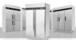
Exterior view of a modern stainless steel refrigerator with open doors and tiered doors (no visible text or symbols)2. Use of the equipment
The refrigerator are for preserving fresh perishable foodstuffs, with an in-built refrigerated unit.
The operating temperature for refrigeration is:
■ between +1°C and +8°C at room temperature of +43°C an 60%RD.
The operating temperature for frozen food maintenance is:
- between -17^ and -22^ at room temperature of +43^ an 60% RD.
3. Technical features
The refrigerator is a ventilated system, the evaporator is in a separate insulated box on the top. All the materials used in the manufacture of this unit are guaranteed to be suitable for use with foodstuffs. The gases used in refrigerator is R134a; in the refrigerator for frozen food maintenance is R404a.
The refrigerating circuit are in compliance with the current normative.
4. Operation
The gas in the refrigerating circuit is in the first time compressed, liquefied and then evaporated in the ventilated evaporator, situated on the top of the container.
This cycle involves the absorption of heath from the air in the refrigerator compartment and the reason is cooled. The heat produced is then dissipated to the outside environment by a condenser unit located on the top of the refrigerator.
5. Control unit
The refrigerator is command from a "digital control unit" and a "main switch pilot light" in the top panel of the refrigerator.
The "main switch pilot light" is for turning on the power supply.
The green pilot light comes on to indicate that the unit is connected to the main electricity and to start work.
The green pilot light comes off to indicate that the unit is disconnected and don't work. The "digital control unit" is for the regulation of all parameters to provide the correct working of the refrigerator. Please consult all parameters in the attachment manual of the "digital control unit".
This manual is part of the instruction manual and is very important in case of service.
6. Handling
The refrigerator arrive in PET film and packed in cardboard box on a wood pallet.

The refrigerator must be transported and handled with care to
avoid posing a hazard to persons or property.
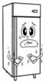
Never place a refrigerator with an in-built refrigerated unit on its side or turn it upside
natural_image
Cartoon illustration of two people standing beside a smiling refrigerator (no text or symbols)down as this may damage or impair operation of the refrigerated unit.
We can not held liable for any damage or defects arising directly or indirectly from improper handling of the equipment or non-compliance with the safeguards illustrated above.
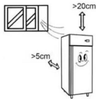
7. Installation procedure
▲ Place the refrigerator in the coolest and best ventilated part of the room. Don’t install the refrigerator in the near of heat and direct sunlight sources.
▲Remove the straps securing the cardboard packing
Remove the cardboard. Covering
Remove the PET protection film
▲ Clean the refrigerator with mild detergent
and then dry it with a soft cloth.
natural_image
Cartoon illustration of a distressed refrigerator with arms and legs, showing facial expressions (no text or symbols)8. Connecting to the main power supply

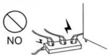
This operation must be carried out by professionally and qualified persons.
The refrigerator are supplied complete with a power supply cable for the connection to the main power supply. A thermomagnetic circuit breaker (not supplied) must be installed between the mains power point and the power supply cable of the refrigerator.
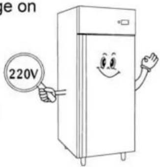
Before proceeding make sure that:
▲ the mains voltage corresponds to the voltage on
the refrigerator 220V/50Hz/1Ph; to ensure proper operation it is essential for the power supply voltage to come within a range of +/- 10% of the unit's rated voltage
▲ the electric system to which the refrigerator is sized to cater for the rated electric output of the buffet unit being installed
▲ the electronic system to which the refrigerator is connected is made in compliance with current standard requirements
▲ the electric connections and the installation of the thermomagnetic circuit breaker have been done by qualified person.
Connecting steps:
▲ Install a thermomagnetic circuit breaker suited to the rated output of the unit being installed
▲ Connect the refrigerator unit to the thermomagnetic circuit breaker outlet
▲ Check that the refrigerator is in order as demonstrated by the pilot light incorporated in the main switch coming on
9. Maintenance instructions
The smooth operation and life of the equipment are mainly determined by correct and regular maintenance
Cleaning:
Regular cleaning of the refrigerator unit is strongly recommended each month. Please follow the instructions below.

Disconnect the refrigerator power supply cable from the mains prior to carrying out any type of cleaning operation.
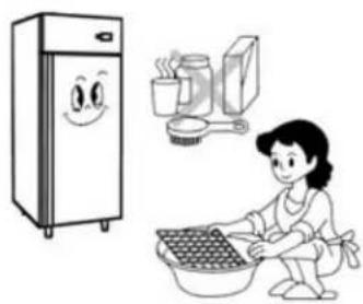
Cleaning the refrigerator surface:
Clean the refrigerator with mild detergent and then dry it with a soft cloth. Do not use abrasive detergents!
natural_image
Illustration of a woman washing clothes next to a refrigerator and kitchen utensils (no text or symbols)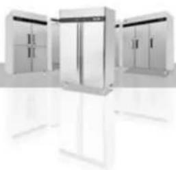
natural_image
Modern stainless steel cabinet with multiple doors and control cabinets, no visible text or symbolsCleaning the inside of the refrigerator:
Clean the inside area min. each month with a detergent suitable for use with foodstuffs.
Cleaning the condenser:
For an efficient operation of the refrigerator it is advisable to clean the condenser regularly approx. every 4 months with a dry brush or vacuum cleaner.
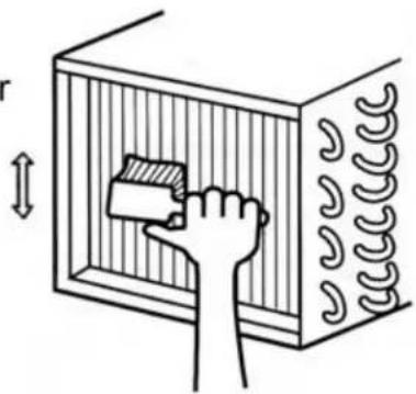
natural_image
Illustration of a hand placing a block into a rectangular chamber with coiled pipes (no text or symbols)10. Troubleshooting
Refrigerator stops working (light off):
☆ Power supply failure
▲ Remedies:
☆ Check that the plug is inserted properly in the socket
☆ Check that the switch on/off
☆ Check that the mains voltage powers the plug
Refrigerator temperature go up:
☆ Unit to near to a heat source
☆ Condenser dirty or close
▲ Remedies:
☆ Move the counter or the heat source further away
☆ Clean the condenser
11. Technical service
For technical service please contact the dealer technical department and give him the serial n°, and the date of buy.
12. Configuration Sketch Map
T Serise Reach-Ins
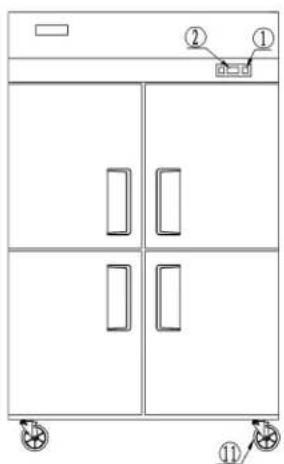
- Power switch
- Evaporator
- Condenser
- Lamp
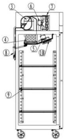
- Microcomputer controller
- Evaporator fan motor
- Drain case
- CASTER
B Serise Reach-Ins
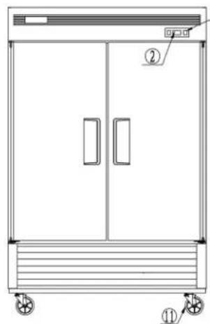
natural_image
Technical line drawing of a two-door industrial cabinet with wheels and labeled components (no text or symbols beyond labels)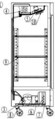
- Compressor
- Condenser fan motor
- Shelf
Operating Instruction
- New upright air-cooling refrigerator should be opened and ventilate it before it is in use. After that, users should use warm water clean its inside.
- After connecting the power supply, press the "POWER" switch on the controller keyboard (Green Indicator Light ON), the fridge will come to work. The microcomputer controller, installed in the controller keyboard, could automatically adjust the temperature ranges. This intelligent digital controller works as: if the temperature increases and reaches set point plus differential the compressor is started and then turned off when the temperature reaches the set point value again.
natural_image
Black and white photo of a digital alarm clock with control panel, no visible text or symbols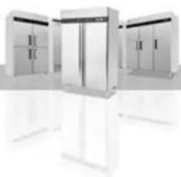
natural_image
Modern stainless steel refrigerator units with open doors and white stands (no visible text or labels)-
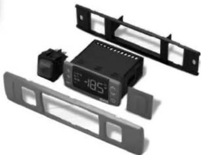
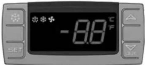
Microcomputer Controller Operation Instruction:
-
Microcomputer panel sketch map, meanings of running indicator light and LED showing.
-
SET To display target set point, in programming mode it selects a parameter or confirm an operation.
(Mod. XR06CX)
To start a manual defrost.
△ In programming mode it browses the parameter codes or increases the displayed value.
In programming mode it browses the parameter codes or
decreases the displayed value.
+ To lock or unlock the keyboard SET+ To enter in programming mode SET+ To return to room temperature display.
| LED | MODE | SIGNIFICATO |
| On | Compressor enabled | |
| Flashing | Anti short cycle delay enabled (AC parameter) | |
| On | Defrost in progress | |
| Flashing | Dripping in progress | |
| On | Fans output enabled | |
| Flashing | Fans delay after defrost | |
| °C | On | Measurement unit |
| Flashing | Programming mode | |
| °F | On | Measurement unit |
| Flashing | Programming mode |
- How to see the point .
Push and immediately release the SET key, the set point will be showed; Push and immediately release the SET key or wait about 5s to return to normal visualisation.
- How to change the setpoint.
Push the SET key for more than 2 seconds to change the Set point value; The value of the set point will be displayed and the “°C” or “°F” LED starts blinking;
To change the Set value push the △ or ▽ AUX arrows.
To memorise the new set point value push the SET key again or wait 10s.
- How to start a manual defrost.
Push the DEF ✦ key for more than 2 seconds and a manual defrost will start.
- How to change a parameter value
To change the parameter's value operate as follows:
Enter the Programming mode by pressing the SET+▼ keys for 3s ("°C" or "°F" LED starts blinking).
Select the required parameter. Press the "SET" key to display its value Use △ or ▽_ALK to change its value.
Press "SET" to store the new value and move to the following parameter.
To exit: Press SET+△ or wait 15s without pressing a key.
NOTE: the set value is stored even when the procedure is exited by waiting the time-out to expire.
- To lock the keyboard.
Keep pressed for more than 3s the ▽+△ keys.
The "OF" message will be displayed and the keyboard will be locked. If a key is pressed more than 3s the "OF" message will be displayed.
- To unlock the keyboard.
Keep pressed together for more than 3s the ▽+△ keys till the "on" message will be displayed.
- Alarm signalling.
| Mess. | Cause | Outputs |
| "P1" | Room probe failure | Compressor output according to “Cy” e “Cn” |
| "P2" | Evaporator probe failure | Defrost end is timed |
| "HA" | Maximum temperature alarm | Outputs unchanged |
| "LA" | Minimum temperature alarm | Outputs unchanged |
| "EA" | External alarm | Outputs unchanged |
| "CA" | Serious external alarm | All outputs OFF |
| "dA" | Door Open | Compressor and fans restarts |
Our products have been modified precisely before leaving factory, so to avoid damaging compressor unit or other malfunctions, users mustn't modify the microcomputer parameters privately.
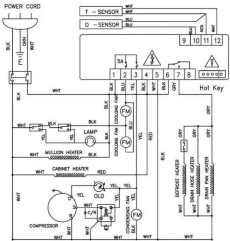
Electrical Control Circuit Diagram
Fan cooling chill series product
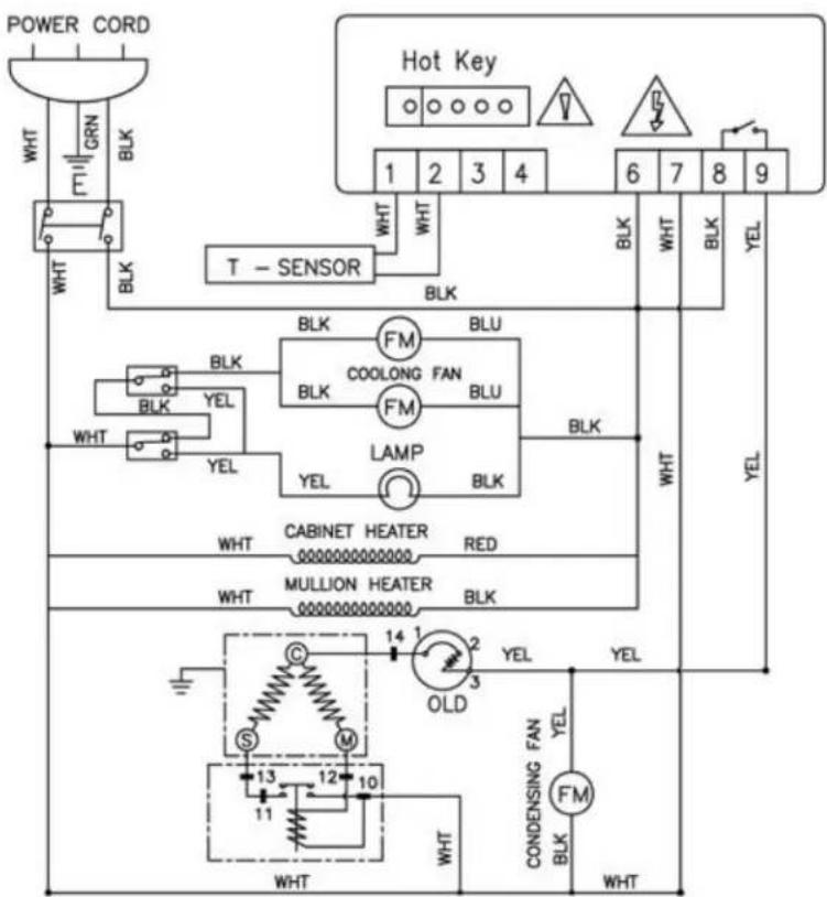
natural_image
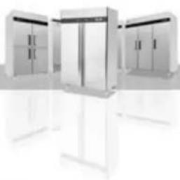
Exterior view of three modern office cabinets with open doors (no signage or text visible)Fan cooling freeze series product
Technical Parameters
T Series Reach-Ins
| Product Name | Model code | Prevention class of getting an electric shock | Power source (V) Rating frequency(Hz) | Rated current(A) | Temperature range (°C) | Refrigerant | Dimension (mm) | Net Weight (kg) |
| Single-door freezer | MBF8001 | I | 220~240/50 | 3 | -22~-17 | R404a | 730×845×2130 | 120 |
| Two-door freezer | MBF8002 | I | 220~240/50 | 4 | -22~-17 | R404a | 1314×845×2130 | 185 |
| Three-door freezer | MBF8003 | I | 220~240/50 | 5 | -22~-17 | R404a | 1976×845×2130 | 280 |
| Single-door refrigerator | MBF8004 | I | 220~240/50 | 2.3 | +1~+8 | R134a | 730×845×2130 | 120 |
| Two-door refrigerator | MBF8005 | I | 220~240/50 | 2.8 | +1~+8 | R134a | 1314×845×2130 | 175 |
| Three-door refrigerator | MBF8006 | I | 220~240/50 | 4 | +1~+8 | R134a | 1976×845×2130 | 280 |
| Half two door freezer | MBF8007 | I | 220~240/50 | 3 | -22~-17 | R404a | 730×845×2130 | 120 |
| Half four door freezer | MBF8008 | I | 220~240/50 | 4 | -22~-17 | R404a | 1314×845×2130 | 185 |
| Half six door freezer | MBF8009 | I | 220~240/50 | 5 | -22~-17 | R404a | 1976×845×2130 | 280 |
| Half two door refrigerator | MBF8010 | I | 220~240/50 | 2.3 | +1~+8 | R134a | 730×845×2130 | 120 |
| Half four door refrigerator | MBF8011 | I | 220~240/50 | 2.8 | +1~+8 | R134a | 1314×845×2130 | 175 |
| Half six door refrigerator | MBF8012 | I | 220~240/50 | 4 | +1~+8 | R134a | 1976×845×2130 | 280 |
| Single-door freezer | MBF8113 | I | 220~240/50 | 3 | -22~-17 | R404a | 730×845×2130 | 120 |
| Two-door freezer | MBF8114 | I | 220~240/50 | 4 | -22~-17 | R404a | 1314×845×2130 | 185 |
| Three-door freezer | MBF8115 | I | 220~240/50 | 5 | -22~-17 | R404a | 1976×845×2130 | 280 |
| Single-door refrigerator | MBF8116 | I | 220~240/50 | 2.3 | +1~+8 | R134a | 730×845×2130 | 120 |
| Two-door refrigerator | MBF8117 | I | 220~240/50 | 2.8 | +1~+8 | R134a | 1314×845×2130 | 175 |
| Three-door refrigerator | MBF8118 | I | 220~240/50 | 4 | +1~+8 | R134a | 1976×845×2130 | 280 |
NOTES :
If the technical data has any changes, we will not notify you any longer.
B Series Reach-Ins
| Product Name | Model code | Prevention class of getting an electric shock | Power source (V) Rating frequency(Hz) | Rated current(A) | Temperature range (°C) | Refrigerant | Dimension (mm) | Net Weight (kg) |
| Single-door freezer | MBF8501 | I | 220~240/50 | 3 | -22~-17 | R404a | 685×800×2135 | 120 |
| Two-door freezer | MBF8502 | I | 220~240/50 | 4 | -22~-17 | R404a | 1003×800×2135 | 160 |
| Two-door freezer | MBF8503 | I | 220~240/50 | 4 | -22~-17 | R404a | 1382×800×2135 | 190 |
| Three-door freezer | MBF8504 | I | 220~240/50 | 5 | -22~-17 | R404a | 2079×800×2135 | 280 |
| Single-door refrigerator | MBF8505 | I | 220~240/50 | 2.3 | +1~+8 | R134a | 685×800×2135 | 115 |
| Two-door refrigerator | MBF8506 | I | 220~240/50 | 2.8 | +1~+8 | R134a | 1003×800×2135 | 155 |
| Two-door refrigerator | MBF8507 | I | 220~240/50 | 2.8 | +1~+8 | R134a | 1382×800×2135 | 180 |
| Three-door refrigerator | MBF8508 | I | 220~240/50 | 4 | +1~+8 | R134a | 2079×800×2135 | 280 |
OFFICIAL APPROVAL AND RULES
Our products full fill the present E.U. rules, including the CE mark of the European official approval
89/336/EEC including amendments-electromagnetic compatibility (EMC)
73/23/EEC including amendments-low voltage (LVD)
EN 60335-1:2005
EN 60335-2-24:2004
EN 55014-1:2003
EN 55014-2:2002
EN 61000-3-2:2001
EN 6100-3-3:2002
Serial No C003-106-076
CE
@20110906
W0811077.20111103

- INSTRUCTION MANUAL
- VERTICAL COOLER
- Content:
- Preface
- ATTENTION
- The manufacturer cannot be held liable in the following cases:
- Use of the equipment
- Technical features
- Operation
- Control unit
- Handling
- Installation procedure
- Connecting to the main power supply
- Before proceeding make sure that:
- Connecting steps:
- Maintenance instructions
- Cleaning:
- Cleaning the refrigerator surface:
- Cleaning the inside of the refrigerator:
- Cleaning the condenser:
- Troubleshooting
- Technical service
- Configuration Sketch Map
- Operating Instruction
- Electrical Control Circuit Diagram
- Technical Parameters
- NOTES :
- OFFICIAL APPROVAL AND RULES
Mærke : Atosa
Model : Commercial MBF8001
Kategori : Fryser