
SL906-L 520 - Emhætte SIRIUS - Gratis brugsanvisning og manual
Find enhedens vejledning gratis SL906-L 520 SIRIUS i PDF-format.

Brugerspørgsmål om SL906-L 520 SIRIUS
0 spørgsmål om dette apparat. Besvar dem du kender, eller stil dit eget.
Stil et nyt spørgsmål om dette apparat
Download vejledningen til din Emhætte i PDF-format gratis! Find din vejledning SL906-L 520 - SIRIUS og tag din elektroniske enhed tilbage i hånden. På denne side er alle dokumenter nødvendige for brugen af din enhed offentliggjort. SL906-L 520 af mærket SIRIUS.
BRUGSANVISNING SL906-L 520 SIRIUS
GBINSTALLATION, USE AND MAINTENANCE INSTRUCTION
SL-EM906 / SL906 1Mot. / SL906 2Mot. /SL907 SL-EM906-L / SL906-L 1 MOT / SL906-L 2 MOT
TECHNICAL INFORMATION
TYPE: FSLC
The symbol on the product or on its packaging indicates that this product may not be treated as household waste. Instead it shall be handed over to the applicable collection point for the recycling of electrical and electronic equipment. By ensuring this product is disposed of correctly, you will help prevent potential negative consequences for the environment and human health, which could otherwise be caused by waste handling of this product. For more detailed information about recycling of this product, please contact your local city office, your household waste disposal service or the shop where you purchased the product. This appliance is marked according to the European directive 2002/96/EC on waste electrical and electronic equipment (WEEE).
ina
CONTENTS
GB
Warnings
Uses
Installation
Working
Maintenance
WARNINGS
ensuring omnipolar disconnections from the grid, with an opening distance between contacts of at least 3 mm, then such disconnecting devices must be supplied within the fixed installation.
- The cooker surface and the inferior part of the cooker hood must be at a minimum distance of 65~cm . To ensure good performances of the product is recommended to install the hood centrally with respect to the cook top (Fig.18).
- The air sucked can't be conveyed through or into a duct used to let out fumes from appliances fed by energy other than electric power (eg. centralized heating, radiators, water-heaters, etc.).
- Attention: remove any possible pvc film from the stainless steel.
- To evacuate the air outlet, please comply with the pertaining rules given by competent authorities.
- Provide the room with an adequate when a cooker hood and appliances fed by energy other than electric power (gas-, oil-, or coal-stoves, etc.) are used simultaneously. Tker hood, when evacuating the sucked air, could generate a negative pressure in the room—which can't exceed the limit of 0.04 mbar, in order to avoid the suck of exhausts deriving from the heat source. Therefore the room should be with air-intakes to allow a costant flow of fresh a
If the rating lable in the cooker-hood shows the symbol ☐, the appliance is built in class II° and it does not need any earth tion.
If the rating lable in the cooker-hood not show the symbol , the a built in class 1° and it needs the earth nection.
- When performing the electrical connections on the appliance, please make sure that the current-tap is provided with earth connection and that voltage values correspond to those indicated on the label placed inside the pliance itself.
- Before carrying out any cleaning or retaining operations, the appliance needs to be removed from the electric grid. If the appliance is not provided with a non-separable flexible cable and plug, or with another device
If the fixed appliance is endowed with a supply cord and a plug, the appliance has to be put in a place where the plug can be reached easily.
- The use of materials which can burst into flames should be avoided in close proximity of the appliance. When frying, please pay particular attention to fire risk due to oil grease. Being highly inflammable, fried oil is especially dangerous. Do not use uncovered electric grills. In order to avoid possible fire risk, all instructions for grease-filter cleaning and for removing eventual grease deposits should be strictly followed.
aeration
USES
The coo-
The appliance is already arranged both f filtering and for suction performances.
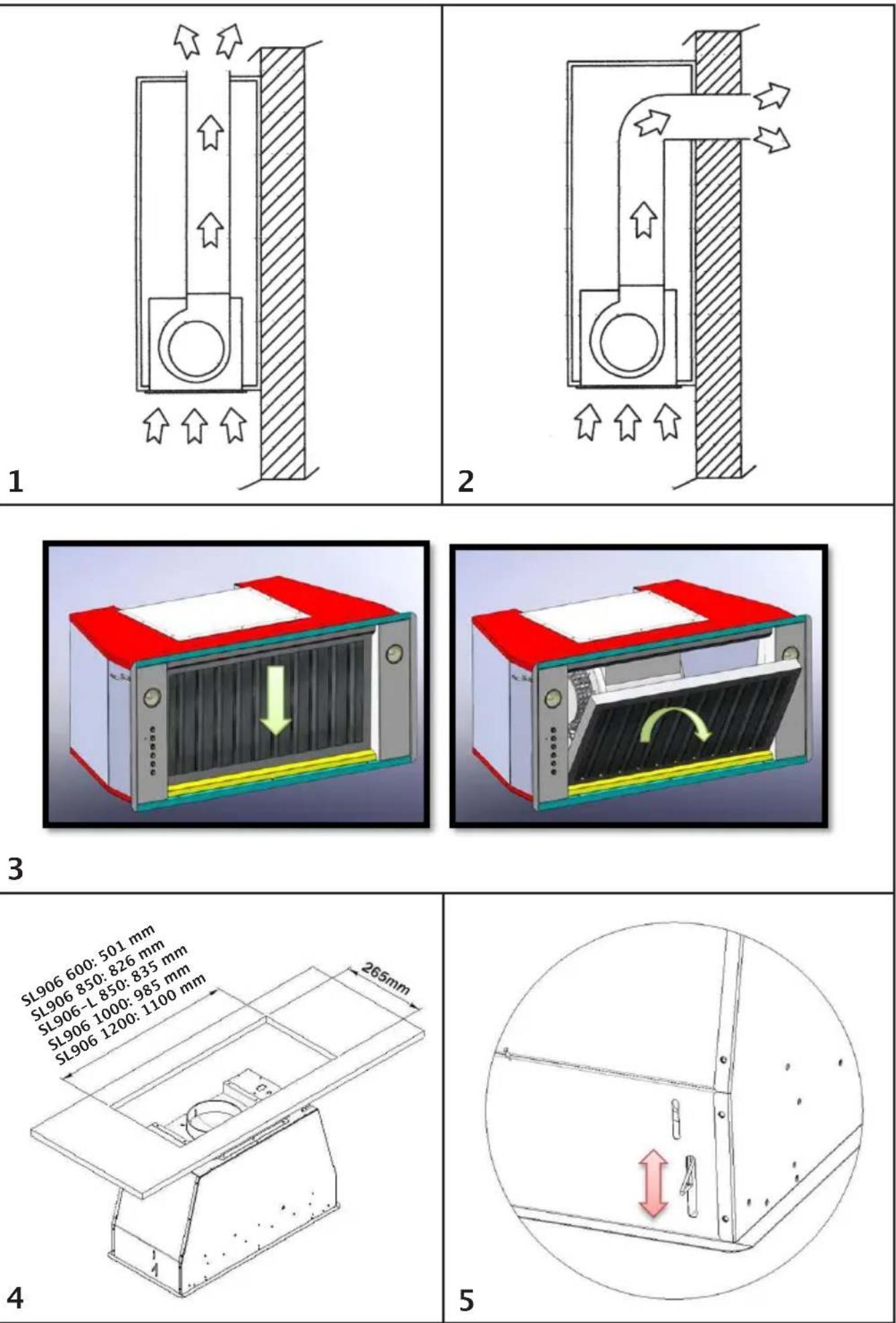
^t = In, its filtering version (Fig.1), the air and provided fumes conveyed by the appliance are depured both by a grease filter and by an active coal filter, and put again into circulation through the hole made on the top of the cabinet.
connec- In its sucking version (Fig.2), fumes are di- rectly conveyed outside, through an evacua- tion duct connected with the superior part of d does the wall or the ceiling. Both coal filter and air appliance is deflector are not necessary in this case. con-
INSTALLATION SL906
the Before installing the appliance, make sure that none of the parts is damaged in any way. In case of damaged parts, contact your retailer and do not proceed with installation.
Read all of the following instructions with care before installing the appliance.
- Use an air outlet pipe of the shortest possible length.
- Limit the number of pipe bends.
- Use a material approved by standards and regulations.
- Avoid any sudden changes in pipe section (recommended constant diameter: ∅ 150 mm / ∅ 200 mm or equal surface area).
- Before installing the appliance, in not to damage the appliance itself, the metal grase filter should be removed. These could be removed by pushing the handles towards the back side of the cooker hood and turning it downwards to unfasten it from its slot. (Fig.3).
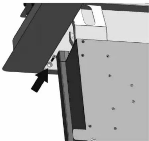
screws (fig.5), according to the thickness of the board previously drilled, on which the appliance will be fixed.
Insert the built-in unit in the hole made the cabinet until the stop click of the springs is heard and the built-in unit is blocked. Insert the screws provided in the holes outside the appliance (fig.6) to block it pletely. filter
Put the grease filter again
Blocking of the stop valve
Warning!
To install the appliance please respect follow instructions.
The appliance must be install by con authorities. In order to do not damage electronic parts of the appliance please not use added screws.
Before connecting the flexible exhausting pipe to the motor, make sure the stop valve,
patient is on the air outlet of the mot gewirge do
Essential precautions to respect before stalling the appliance are the following:
To have made a cut-out on the bottom of the cabinet which is suitable to hold the appliance in position (dis. 4):
SL906 da 600 501x265mm, SL906 da 850 826x265mm, SL906-L da 850 835x265mm, SL906 da 1000 985x265mm, SL906 da 1200 1100x265mm.
- prepare the power supply. - prepare a hole for the exhaust both in the filtering and in the exhausting version.
- Use an exhausting pipe whose max length does not exceed 5 meters.
Do not use screws to fix the outlet pipe to the cooker hoods.
- Limit the no. of elbows in the piping, since each elbow reduces the aspiration efficiency of 1 linear meter. (Ex.: if you use no. 2 x 90° elbows, the length of piping I must not exceed 3 meters)
- Avoid abrupt direction changes.
- Use a 150 mm constant diameter pipe for the whole length.
- Use piping approved by standards in force.
Exhausting version
Connect the flange to the exhausting ho with an appropriate pipe. Connect the appliance with the electrical mains through the supply cord.
Filtering version
Connect the flange with a pipe suitable convey the air to the top of the cabinet. Connect the appliance with the electrical ma through the supply cord.
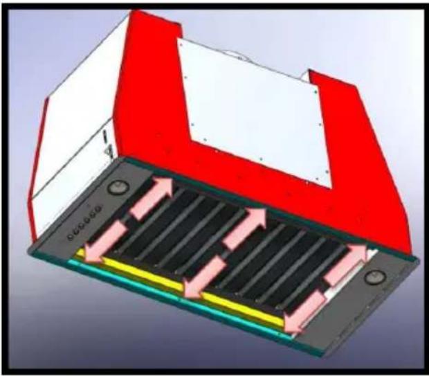
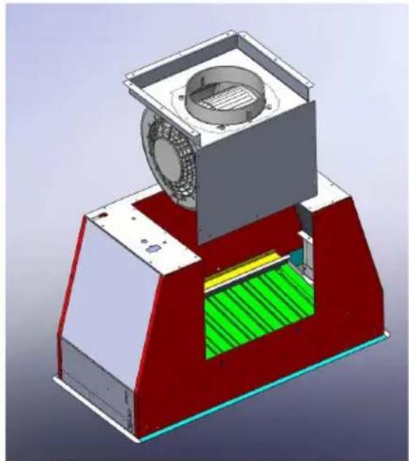
Rear vented version
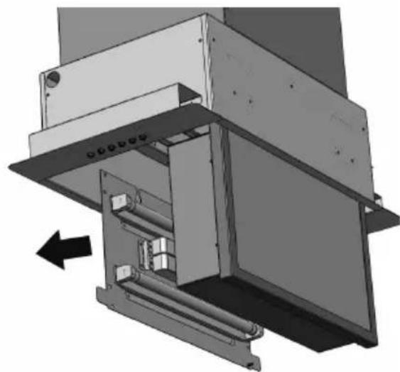
of Allthetheair models with one motor can be vented; if the customer wants to use this option, it is necessary to remove the 18 screws from the motor group support. Then take the aximetal support with motor included out (11a). Turn the motor to have the air on the rear side (pic. 11b) and fix the screws previously removed.
In the units equipped with 2 motors please use a 200mm constant diameter pipe for the whole length.
To install the appliance, adjust the position of the stop side-springs using the appropriate
INSTALLATION SL907
WORKING
Before installing the appliance, make that none of the parts is damaged in any way. In case of damaged parts, contact your retailer and do not proceed with installation. Read all of the following instructions care before installing the appliance.
- Use an air outlet pipe of the shortest possible length.
- Limit the number of pipe bends.
- Use a material approved by standards and regulations.
- Avoid any sudden changes in pipe section (recommended constant diameter: ∅ 150 mm / ∅ 200 mm or equal surface area).
Before carrying out installation, please remove the grease filter in order to avoid possible damages to the appliance. Please follow the following steps to remove the metal filter: open the lighted panel first, by turning it downwards (fig.12), then remove the grease filter by operating on its handle and making the filter rotate downwards, disengaging it from its seat.
Make a hole on the surface of the following dimensions (dis. 16):
270mm x 498mm for SL907 52cm model 270mmx675mm for SL907 70cm model
Insert the SL907 unit, making sure the push-button panel is placed on the right, looking at the product from the front of the cook-top.
Make the electric connection and of the air-outlet flange to a suitable exhausting pipe.
Fix the unit by using the four screws provided and tighten them as shown in fig. 13.
Insert the grease filter again and close ^ast -the perimeter panel.
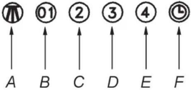
Mod. S906–S907 (fig. 10)
A: Light switch on/off
B: Motor switch on speed 1/off
C: Motor switch on speed 2
D: Motor switch on speed 3
E: Motor switch on speed 4
F: 10-minutes timer
MAINTENANCE
- An accurate maintenance guarantees good functioning and long-lasting performance.
- Particular care is due to the grease filter panel. It can be removed by pushing its special handle toward the back-side of the cool hood and turning the filter downwards so to unfasten it from its slot (Fig.3).
To insert the filter just perform the opposite operation.
After 30 hours working, the push button control panel will signal the saturation of the grease filter by lighting all the buttons. Press the timer button to reset ⏻.
The grease filter needs cleaning by regu hand-washing or in dishwashers every two months at least or depending on its use.
- In case the appliance is used in its filtering version, the active coal filter (Fig.7) needs to be periodically replaced. The coal filter could be removed by removing the grease filter first (Fig.3), and by pulling its special plastic tongue until it is unfastened from its s Re-insert the coal filter by operating in opposite way.
The coal filter needs replacing depending on the use, but however every six months at le-
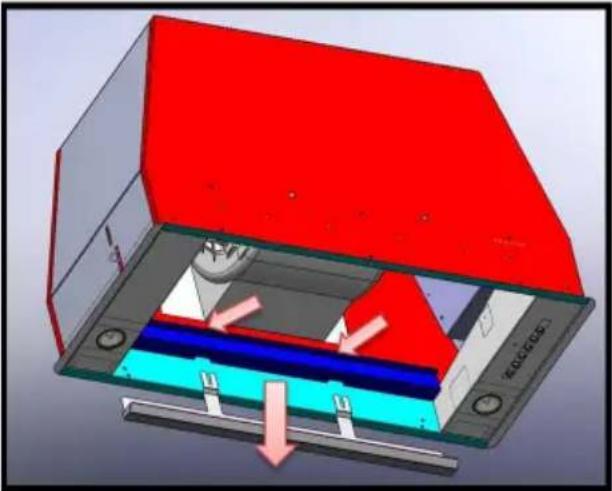
- How to remove the oil collector. After having removed the grease filters and eventually the active coal filters, please hold the oil tank up by one hand and ioosen the three handles by the other hand as showed in fig.8. Then let the tank slide downwards making attention in order to avoid the leak of oil.
- To clean the appliance itself tepid water and neutral detergent are recommended, while abrasive products should be avoided. For steel appliances specialized detergents are recommended (please follow the instructions indicated o the product itself to obtain the desired results).
- Warning! To take down the appliance from the cabinet, remove the definitive fixing screws (fig. 6) using a screw-driver, get off the grease filters (fig.3) and the active carbon filters, if they are inserted (fig. 7).
Act on the small handle of the springs, which are inside the built-in unit, with the necessary strength to unhook the appliance from the cabinet.
* If the supply cord is damaged, it must be replaced by the manufacturer or its sevice agent or a similarly qualified person in order to avoid a hazard.
Replace the dichroic lamp SL906, remove the lamp (fig.9) by inserting a screwdriver or another sharp too between the lamp and its chrom support and replace it with a l'appareil lamp of the same kind.
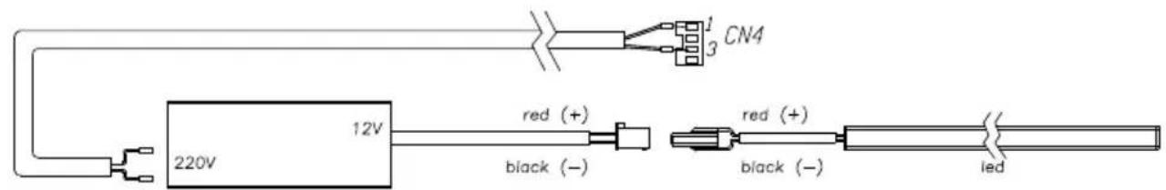
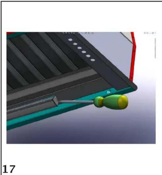
Replace the led bar SL 906-L
Before to replace the led bar switch off the appliance then by using appropriate tools remove the led bar from its slot (fig.17). Take out the led bar from its connector and replace with similar characteristics. To find the correct led bar please check on the replacement part list.
Replacement of SL 907 fluorescent lamp
To replace the fluorescent lamps of SL907 model, you need to open the perimeter panel, by rotating it as shown in Fig. 11, remove the panel fixing screws (fig. 13), paying special care in holding it during this step, then remove the lamps and replace the damaged one (fig. 14).
Insert the panel again.
If the supply cord is damaged, it must be replaced by the manufacturer or its service agent or a similarly qualified person in order to avoid a hazard.
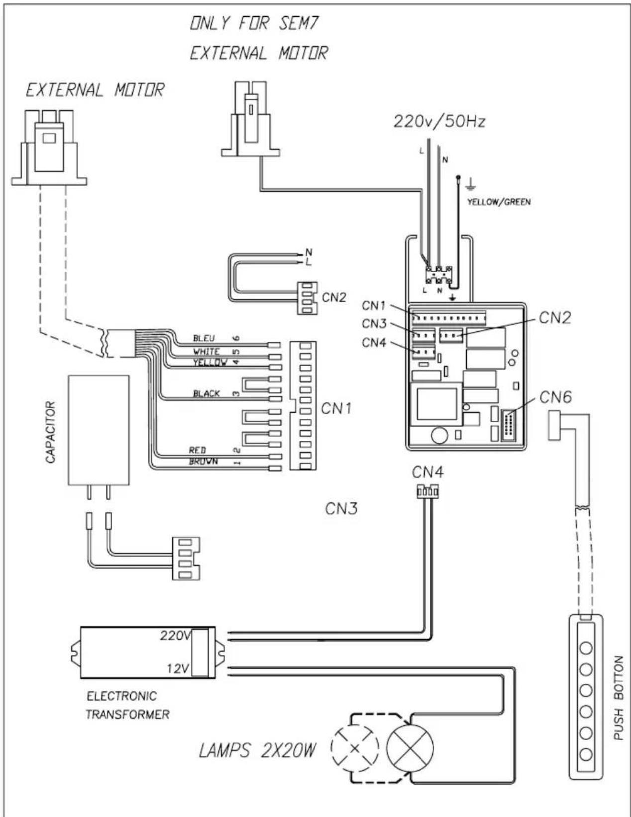
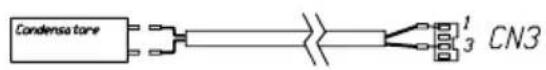
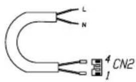
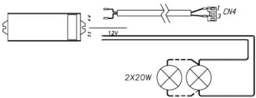
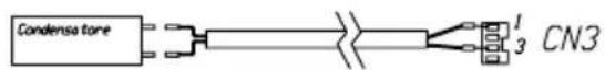
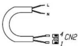
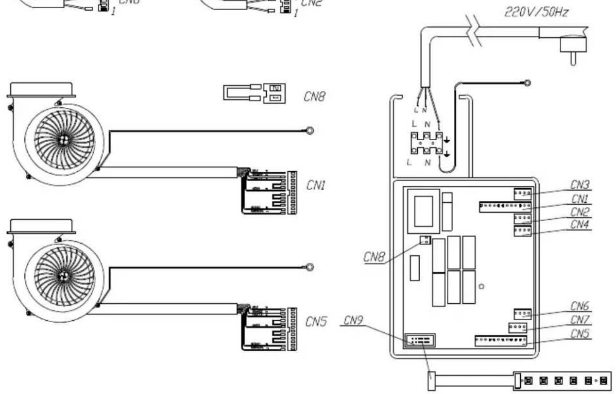
WIRING DIAGRAM SL-EM906
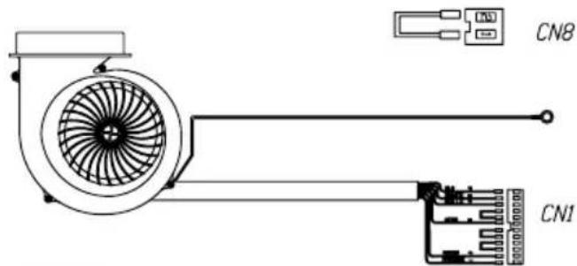
WIRING DIAGRAM SI906 1motor
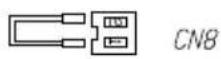
CN8
natural_image
Technical line drawing of a fan assembly with internal components and wiring (no text or symbols)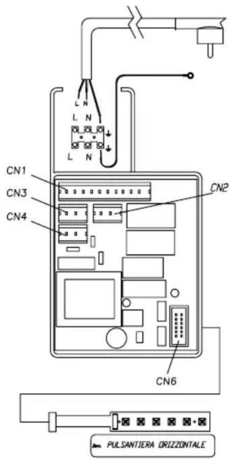
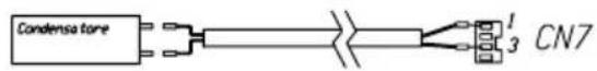
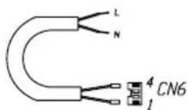
WIRING DIAGRAM SI906 2motors
natural_image
Technical line drawing of a fan assembly with internal components and wiring (no text or symbols)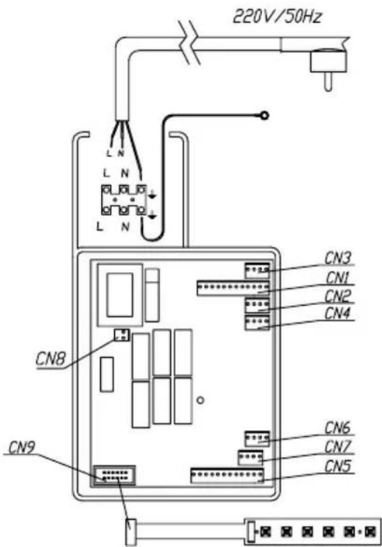
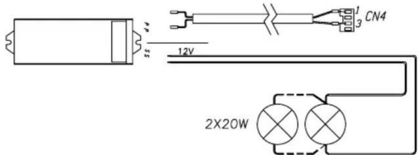
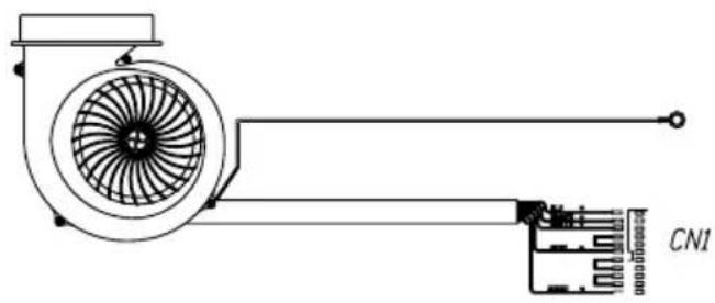
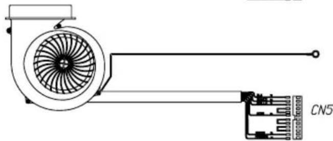
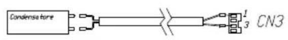
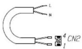
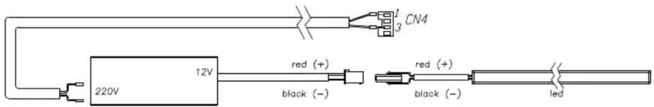
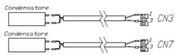
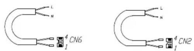
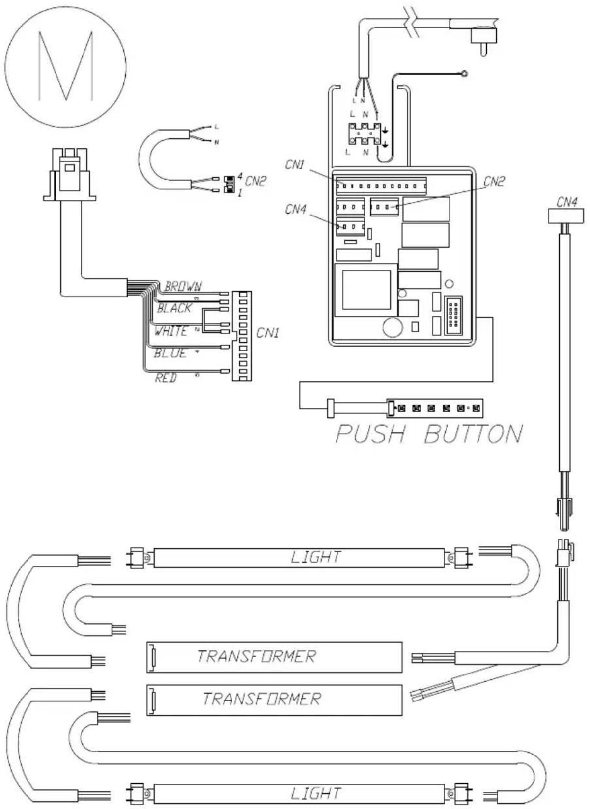
WIRING DIAGRAM SL906-L 1motor
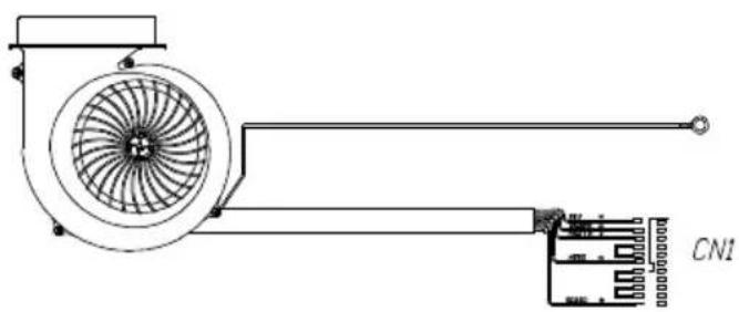
natural_image
Technical line drawing of a fan assembly with labeled component CN1 (no text or symbols beyond label)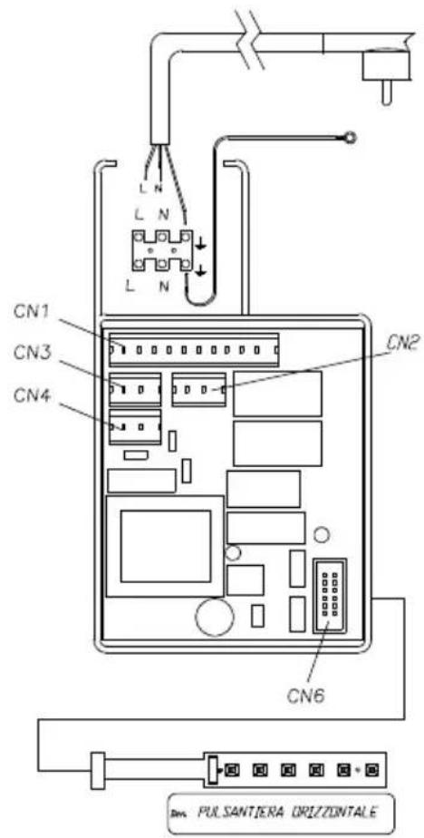
WIRING DIAGRAM SL906-L 2motors
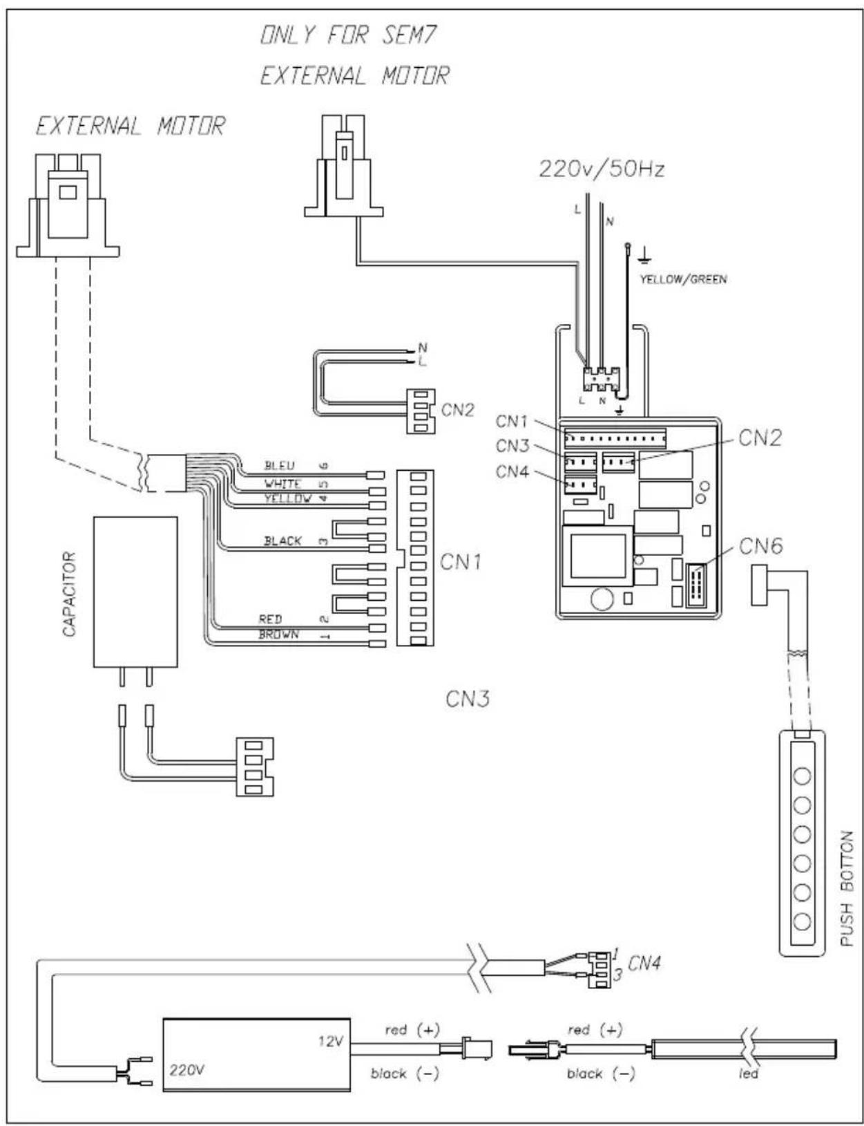
WIRING DIAGRAM SL-EM906-L
WIRING DIAGRAM SL907
 6 6 | 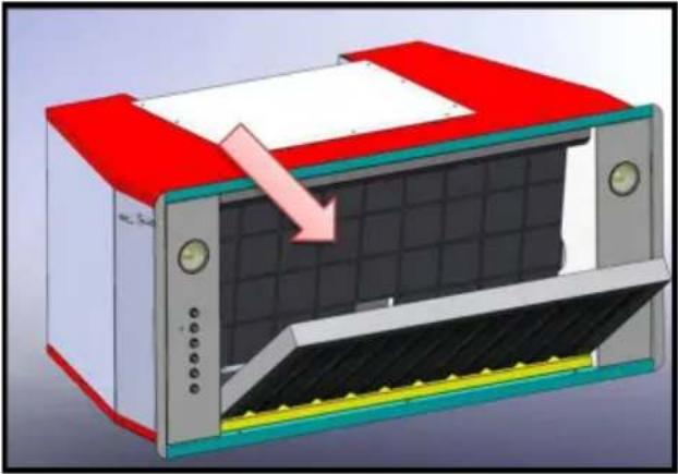 7 7 |
 8 8 | 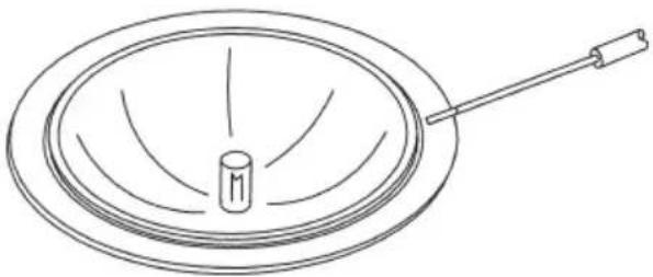 9 9 |
 10 10 | 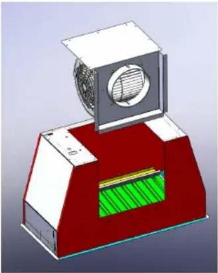 11a 11a |
 11b 12 11b 12 | 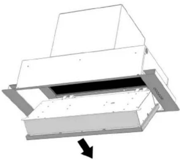 |
 13 13 | 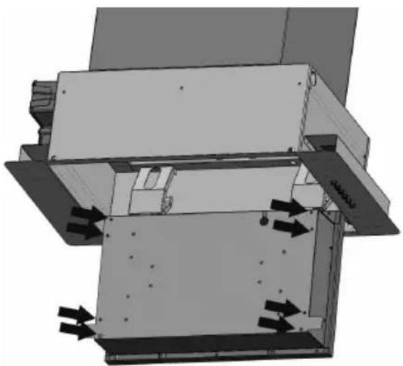 14 14 |
 15 15 | 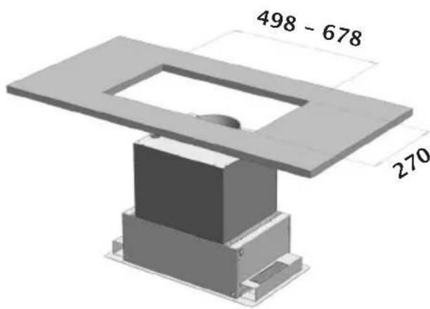 16 16 |
natural_image
3D rendered mechanical component with green and yellow parts, no visible text or symbols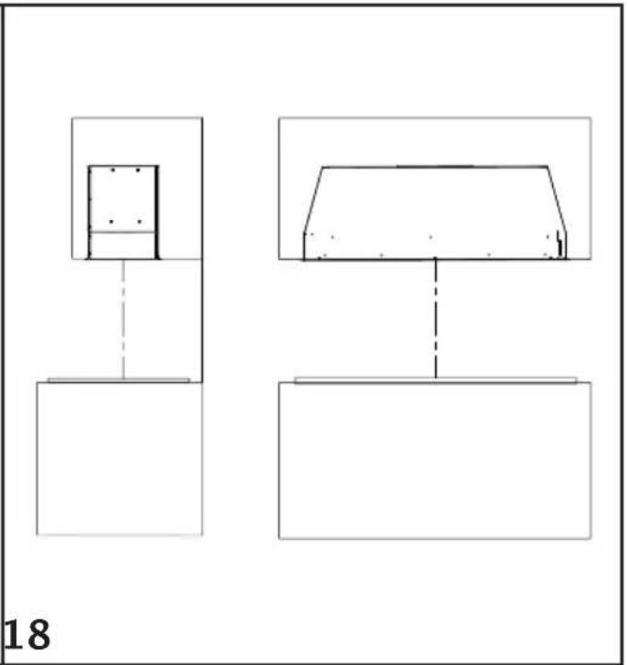
natural_image
Two simple line drawings of architectural or mechanical components, one with a rectangular base and vertical dashed line, the other with a trapezoidal frame and horizontal dashed line (no text or symbols)Mærke : SIRIUS
Model : SL906-L 520
Kategori : Emhætte