
R9004787 - Extension AV Barco - Gratis brugsanvisning og manual
Find enhedens vejledning gratis R9004787 Barco i PDF-format.

Brugerspørgsmål om R9004787 Barco
0 spørgsmål om dette apparat. Besvar dem du kender, eller stil dit eget.
Stil et nyt spørgsmål om dette apparat
Download vejledningen til din Extension AV i PDF-format gratis! Find din vejledning R9004787 - Barco og tag din elektroniske enhed tilbage i hånden. På denne side er alle dokumenter nødvendige for brugen af din enhed offentliggjort. R9004787 af mærket Barco.
BRUGSANVISNING R9004787 Barco
BARCO
Event Master EX – Screen Management System:
Expansion Box
Quick Start Guide
Barco Technical Support:
USA: +1 (866) 374-7878
EMEA: +32 (56) 36 8019
China: 40088 22726
APAC: +603-78803362
Support: www.barco.com/en/support

The EX expansion box ships without input or output cards. Cards must be installed before you set up and operate the unit. Cards are not hot-swappable.
Quick Setup and Operations
-
Connect all sources, displays, and peripherals to the EX extension box according to your event's requirements.
-
Power up the EX and all peripherals.
-
Set up the computer on which you will run the Event Master control software for a static IP address of 192.168.0.200.
The network ID must be 192.168.0. You may assign the host ID yourself, but avoid the default static IP address, which is 192.168.0.185.
If you plug the USB thumb drive into the EX expansion box, the system creates a "whoareyouEX.txt" file that contains the IP address and the Unit ID.
-
Connect the EX unit via an Ethernet cable to a computer on which the Event Master control software is installed.
-
Use the front-panel LED to verify that the EX is running correctly.
On power up, the LED may be in one of four states:
Solid red - The operating system is running.
- Quickly blinking red – 3 fast blinks indicates overheating.
- Steadily blinking red – 1 blink per second indicates PCIe errors.
- Solid green – The main code is running; the system is ready.
Identify EX Units
-
Select the EX unit (in the Selection area or the Diagram area).
-
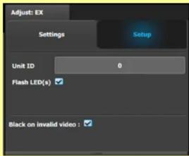
Go to the Adjust tab in the Configuration area.
-
Select the Setup sub-tab and check the Flash LED(s) box. The front and rear status LEDs of the selected EX unit will blink.
Recessed Reset Switch
Status LED USB 2.0 Port

Refer to the Event Master devices User's guide (R5905948) for detailed system specifications, descriptions and operation instructions.

Linking
An Event Master unit can link with other Event Master units. Depending on the linking configuration, linked units share inputs, and they expand the number of outputs. For more information on linking, see Section 6.17 "Configuration Menu > Linking" in the Event Master Devices User's Guide, or see the instructional videos on the Barco Folsom IP YouTube site.
For links to other quick-start guides and the Event Master Devices User's Guide, see the Technical Downloads tab for each product on the Barco Presentation switchers page at: https://www.barco.com/en/Products/Image-processing/Presentation-switchers
For links to instructional videos, see the Barco Folsom IP YouTube site at: https://www.youtube.com/user/BarcoFolsomIP.
Link Connections
- Check the cable orientation for keying. The cable fits in only one orientation.
- Fully insert the cable into the connector on the Link Card.
- If the cable resists full insertion, do not force it; pull the cable out, check its orientation, and reinsert it.
- Make sure that the latch is properly engaged.
- Always use the release when removing the cable.
Improper insertion or removal of Link cables can damage the connectors and is not covered under the product warranty.
Example: Linking an EX (or a Pair of EX Units) to an E2
Each E2 is equipped with two link cards, always located in slots 1 and 2. Link cards are identified by a yellow stripe at the top.
Each EX has two Link sockets.
Be sure that you properly align the Link cable connectors prior to insertion. Connectors should insert easily with almost no resistance, until the lock is about to engage. Be sure that the lock engages fully to ensure proper contact. Make sure that you use the locking mechanism and then push each cable until it locks in place.
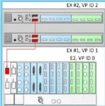
- To link an EX to an E2, connect the Link cables from the E2 to the EX as follows:
E2 VP ID 0, Link Card slot 1, Link 1 >> EX VP ID 1, Link 2
- To link two daisy-chained EX units to an E2, connect the Link cables from the E2 to the EXes as follows: E2 VP ID 0, Link Card slot 1, Link 1 >> EX VP ID 1, Link 2 EX VP ID 1, Link 1 >> EX VP ID 2, Link 2
- Make sure that the E2 and the EX unit (or units) have different IP addresses.
The E2 default IP address is 192.168.0.175, and the EX default IP address is 192.168.0.185. If more than one EX is linked, be sure to change the IP addresses on additional units.
- Connect all devices to network Ethernet.
- Start the Event Master Toolset version 4.0 or higher.
- Drop the E2 in the GUI. The EX unit cabled to the E2 appears as a grayed-out box below the E2 unit in the Diagram area. In the grayed-out EX box a blue button allows you to add the EX to the system as a slave.
- Click the blue add button to add the EX unit.
If you are adding two daisy-chained EX units, you must add the first EX in the chain before the second EX in the chain is displayed, then repeat Step 4 to add the second EX in the chain.
Factory Reset
If necessary, press the recessed reset switch and hold it for five seconds to restore the EX extension box to factory settings.
If you press the reset switch and release it after fewer than five seconds, the unit toggles between Static IP mode (LED blinks 2 times) and DHCP mode (LED blinks 3 times).
Power Switch and AC Connector
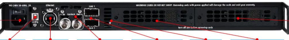
USB 2.0 Port
RJ45 Connector (Ethernet)
Genlock BNC Input and Reference Output
Link Connectors Top = 1 Bottom = 2
Status LED
Card Slot #1 (Any Event Master card)
Card Slot #2 (Any Event Master card)
P/N 26-1502004-00 Rev 02
BARCO
Event Master EX – Screen Management System:
Expansion Box
Quick Start Guide
Barco Technical Support:
USA: +1 (866) 374-7878
EMEA: +32 (56) 36 8019
China: 40088 22726
APAC: +603-78803362
Support: www.barco.com/en/support
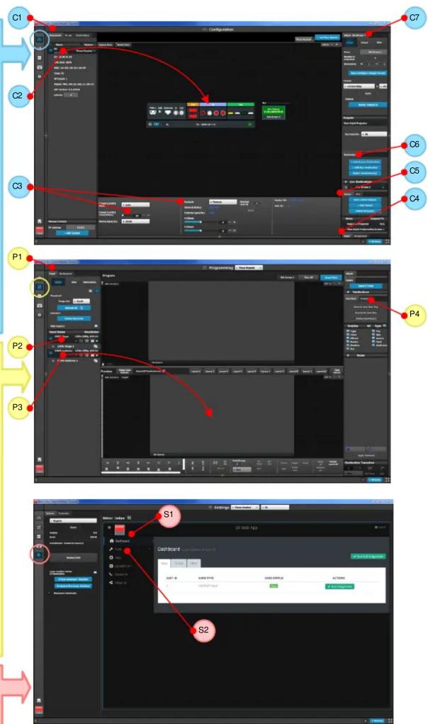
Configuration Menu
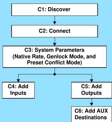
C1: Discovery - The Event Master control software automatically discovers the devices connected to the network and lists them on the left hand side of the configuration screen.
C2: Connect - Click on the device that you want to connect, drag it in the middle area, and the software establishes communication with the unit. You can also connect to the EX by typing the IP address manually.
C3: System Parameters - Select the desired Native Rate, Genlock Mode, and Preset Conflict Mode.
C4: Add Inputs - Select and define input connectors as Inputs.
C5: Add Outputs - Select and define output connectors as Outputs.
C6: Add Aux Destinations - Select the corresponding output connector(s) from the same card and add them to AUX Destinations.
C7: For any Input, Output, or AUX Destination, select the Adjust tab and perform any necessary adjustments.
Programming Menu
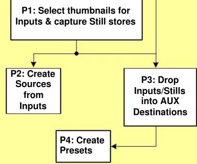
P1: Select thumbnails for Inputs & Stills – Press Refresh All, or select the thumbnails to represent Inputs and Stills. Either capture a live thumbnail or select an image file.
P2: Create Source Files – Under the Input tab create any additional source files (optional). Select the Adjust tab and perform any additional adjustments and press Save. Repeat for all Inputs/ Sources and save.
P3: Drop Inputs to Aux Destinations – Under the Input tab select an Input and drop it to an Aux Destination. Select the Adjust tab and perform any additional adjustments. Repeat for all Inputs and save.
P4: Presets – Select Screen(s) and under Adjust and Preset tabs create a new preset or manage existing ones. Repeat to create multiple Presets.
flowchart
graph TD
    A["C1: Discover"] --> B["C2: Connect"]
    B --> C["C3: System Parameters\n(Native Rate, Genlock Mode, and Preset Conflict Mode)"]
    C --> D["C4: Add Inputs"]
    C --> E["C5: Add Outputs"]
    E --> F["C6: Add AUX Destinations"]
flowchart
graph TD
    A["P1: Select thumbnails for Inputs & capture Still stores"] --> B["P2: Create Sources from Inputs"]
    A --> C["P3: Drop Inputs/Stills into AUX Destinations"]
    C --> D["P4: Create Presets"]
    D --> E["End"]
Settings Menu
S1: The Dashboard provides card status and other diagnostic information.
S2: Tools allow users to perform Backup and Restore operations or to download the latest software from the Barco Web site.


P/N 26-1502004-00 Rev 02
Mærke : Barco
Model : R9004787
Kategori : Extension AV