
D9127U - Ukategoriseret BOSCH - Gratis brugsanvisning og manual
Find enhedens vejledning gratis D9127U BOSCH i PDF-format.


Brugerspørgsmål om D9127U BOSCH
0 spørgsmål om dette apparat. Besvar dem du kender, eller stil dit eget.
Stil et nyt spørgsmål om dette apparat
Download vejledningen til din Ukategoriseret i PDF-format gratis! Find din vejledning D9127U - BOSCH og tag din elektroniske enhed tilbage i hånden. På denne side er alle dokumenter nødvendige for brugen af din enhed offentliggjort. D9127U af mærket BOSCH.
BRUGSANVISNING D9127U BOSCH
D9127 Series POPIT Modules
www.boschsecurity.com

BOSCH
Invented for life
natural_image
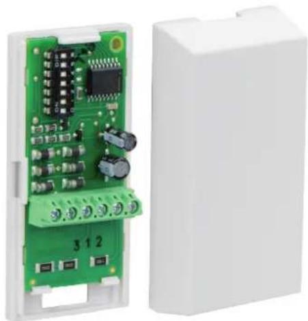
Electronic circuit board with green components and a white plastic housing (no visible text or symbols)The D9127 Series POPIT Modules includes the D9127T (with magnetic tamper switch) and the D9127U (without tamper). They are used with a D8125 or B299 Addressable Expansion Module when there is a need to expand a compatible control panel beyond its standard number of on-board initiating zones or points. Future system expansion is very economical as D9127 Series POPITs can be added anywhere along the two-wire data expansion loop from the D8125 or B299 modules. Both modules include proven technology that combines zone and point supervision with individual device addressing on one pair of wires. Screw terminals provide reliable connections for the data expansion loop and supervised sensor loop wiring. Install a 33 kΩ end-of-line resistor at the farthest point on the loop for proper supervision. The units are small and easily installed in standard outlet boxes, above false ceilings, closets, or other accessible locations.
▶ Provides point identification of initiating devices
▶ Supervises wiring to devices for circuit integrity
▶ Expands the number of points in the system
▶ Compact size
▶ Terminal connections for reliability
Certifications and approvals
| Region Regulatory compliance/quality marks | |
| USA UL | |
| UL UL 365 - Police Station Connected Bur-glar Alarm Units | |
| UL UL 464 - Standard for Audible Signal Ap- pliances | |
| UL UL 609 - Standard for Local Burglar Alarm Units and Systems | |
| UL UL 864 - Standard for Control Units and Accessories for Fire Alarm Systems (10th edition) | |
| UL UL 985 - Household Fire Warning Sys- tem Units (6th edition) | |
| UL UL 1023 - Household Burglar Alarm Sys- tem Units | |
| UL UL 1076 - Proprietary Burglar Alarm Units and Systems | |
| UL UL 1610 - Central Station Burglar Alarm Units | |
| UL UL 1635 - Standard for Digital Alarm Communicator System Units | |
Region Regulatory compliance/quality marks
| FM | ||
| CSFM California State Fire Marshal | ||
| FDNY-CoA | 6059 [D9412GV3 & D7412GV3] | |
| FDNY-CoA | 6286 D7412GV4 D9412GV4 NYC COA 6286 2018-2021 | |
| FDNY-CoA | 6196 | |
| Australia CTICK C-Tick | ||
| Canada ULC CAN/ULC S304 - Standard for Signal Receiving Center and Premise Burglar Alarm | ||
| ULC S303 - Local Burglar Alarm Units and Systems | ||
| ULC ULC 365 - Police Station Connected Burglar Alarm Units | ||
| ULC APOU7.S1871 Proprietary Alarm Units Certified for Canada | ||
| ULC ULC-ORD C1023 - Household Burglar Alarm System Units | ||
Installation/configuration notes
Compatibility Information
Control Panels All G Series control panels, D9412, D7412,
D7212, D7212B1, D9112, D9112B1,
D8112G1, D8112G2, and D9124
Modules D8125, B299
The D8125 or B299 POPEX Modules are required. The D9127 modules are wired in parallel on the D8125 or B299 data loops.
Number of POPIT Modules per Control Panel
D7212G, D7212GV2, D7212GV3 32 D9127 POPITs
D7212B1 40 D9127 POPITs
D7212, D7412, D7412G, D7412GV2, 67 D9127 POPITs D7412GV3, D7412GV4
D9124 119 D9127 POPITs
D9112B1 126 D9127 POPITs
D9112, D9412, D9412G, D9412GV2, 238 D9127 POPITs D9412GV3, D9412GV4
B8512G (D8125) 67 D9127 POPITs
B8512G (B299) 91 D9127 POPITs
B9512G (D8125) 238 D9127 POPITs
B9512G (B299) 591 D9127 POPITs
Wiring Considerations
Wire Size Maximum Length of all Data
Expansion Loops Combined
0.8 mm (22 AWG) 549 m (1800 ft)
1.0 mm (20 AWG) 881 m (2890 ft)
1.2 mm (18 AWG) 1402 m (4600 ft)
1.5 mm (16 AWG) 2231 m (7320 ft)
1.8 mm (14 AWG) 3551 m (11650 ft)
D8125 or B299 POPIT Loops
Use one two-wire data expansion loop, or distribute the POPITs on multiple loops. The maximum lengths shown in the following table are for all data expansion loops combined connected to the same D8125 or B299 module. Setting DIP switches on the POPIT modules assigns them to point numbers. The switch setting on each POPIT assigns it a point number, regardless of its physical location.
POPIT to Sensor Loops
The number of detection devices each sensor loop can supervise is limited only by the resistance on the loop. Resistance on each sensor loop must be less than 100 Ω not including the end-of-line (EOL) resistor. Certain UL and National Fire Protection Association (NFPA) applications can limit the number of detection devices. Consult the appropriate UL or NFPA standards.
Terminate each POPIT sensor loop with the 33 kΩ EOL resistor included with each POPIT.
Use a twisted-pair wire (six twists per foot) in all POPIT installations for both the data expansion loop wiring and the POPIT sensor loops. Run wires away from AC sources to prevent AC induction.
Technical specifications
Environmental Considerations
| Relative humidity Up to 93% non-condensing | |
| Temperature (operating) | 0°C to +60°C (+32°F to +140°F)For UL Certificated Installations, 0°C to +50°C (+32°F to +122°F) |
Properties
| Color | Off white |
| Dimensions 8.1 cm x 3.8 cm x 2.4 cm(3.2 in. x 1.5 in. x 0.9 in.) | |
| Material | UL Listed fire-resistant |
Power Requirements
| Current draw 0.8 mA maximum |
| Resistance Maximum increase in resistance on the POPIT loop is 1000 Ω. Maximum resistance between the D8125 or B299 modules and each POPIT is 90 Ω. |
| Voltage (operating) 12 VDC nominal |
Sensor Loop
| Resistance Maximum resistance on the sensor loop is 100 Ω. |
| Response time 1 sec approximately |
Ordering information
D9127T POPIT input module with tamper
Includes a magnetic tamper switch.
Order number D9127T
D9127U POPIT input module without tamper
No tamper switch.
Order number D9127U
D9127T-CHI POPIT input module with tamper
Includes a magnetic tamper switch.
Order number D9127T-CHI
Represented by:
Europe, Middle East, Africa:
Bosch Security Systems B.V.
P.O. Box 80002
5600 JB Eindhoven, The Netherlands
Phone: +31 40 2577 284
emea.securitysystems@bosch.com
emea.boschsecurity.com
Germany:
Bosch Sicherheitssysteme GmbH
Robert-Bosch-Ring 5
85630 Grasbrunn
Germany
www.boschsecurity.com
North America:
Bosch Security Systems, Inc.
130 Perinton Parkway
Fairport, New York, 14450, USA
Phone: +1 800 289 0096
Fax: +1 585 223 9180
onlinehelp@us.bosch.com
www.boschsecurity.us
Asia-Pacific:
Robert Bosch (SEA) Pte Ltd, Security Systems
11 Bishan Street 21
Singapore 573943
Phone: +65 6571 2808
Fax: +65 6571 2699
apr.securitysystems@bosch.com
www.boschsecurity.asla