
4964140 - Ukategoriseret BRESSER - Gratis brugsanvisning og manual
Find enhedens vejledning gratis 4964140 BRESSER i PDF-format.

Brugerspørgsmål om 4964140 BRESSER
0 spørgsmål om dette apparat. Besvar dem du kender, eller stil dit eget.
Stil et nyt spørgsmål om dette apparat
Download vejledningen til din Ukategoriseret i PDF-format gratis! Find din vejledning 4964140 - BRESSER og tag din elektroniske enhed tilbage i hånden. På denne side er alle dokumenter nødvendige for brugen af din enhed offentliggjort. 4964140 af mærket BRESSER.
BRUGSANVISNING 4964140 BRESSER
Instruction Manual
Art. No. 4964140
Read these operating instructions and the safety instructions carefully before using the product. Keep this manual for future reference.

CAUTION!
This caution icon refers to information pertaining to important safety procedures in preventing injuries and damages which may occur as a result of mishandling this product.

PROHIBITION!
This prohibition icon refers to information pertaining to prohibited contents. Refer to the instructions closely to avoid accidents.
SPECIFICATIONS
HxWxD: 37 x 88 x 46 mm (1.5 x 3.5 x 1.9 in) · Weight: 250 g (0.56 lbs)
Camera screw: U1/4" (10.4in) · Tripod mount screw: U1/4"
Height adjustment angle: 20° (+/- 10°) · Azimuth adjustment angle: 16° (+/- 8°)
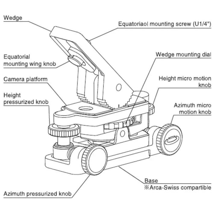
Parts description

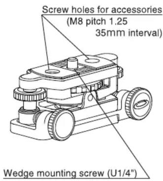
Wedge removed
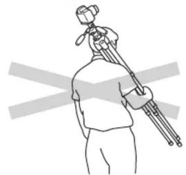
Carrying the tripod
Prohibition
natural_image
Line drawing of a person holding a camera on a tripod, with no text or symbols presentRemove camera and other equipment from the tripod while transporting. Camera or other equipment may fall from the tripod and cause bodily injuly or property damage.
Equipment to be mount
Prohibition
Max. load capacity : 6kg
DO NOT load more than its load capacity. Also, it may be difficult to balance the equipment due to its position of center of gravity even below the load capacity. Tripod must have enough load capacity. The center of gravity may be greatly shifted depending on the equipment used. To correct the center of gravity of the equipment, adjust mounting position of the camera platform and slide mounting position of the wedge.
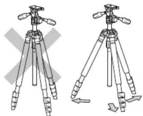
Setting up
Caution
natural_image
Two identical line drawings of a tripod with adjustable legs and handles, no text or symbols present.To prevent accidental equipment fall or tripod tipping over, making sure all levers, knobs and handles on the unit are securely tightened. Also, spread tripod legs as wide as possible for a solid foundation. Insufficient leg spread may cause camera shake and the tripod to fall over
Installation (mounting on the tripod)
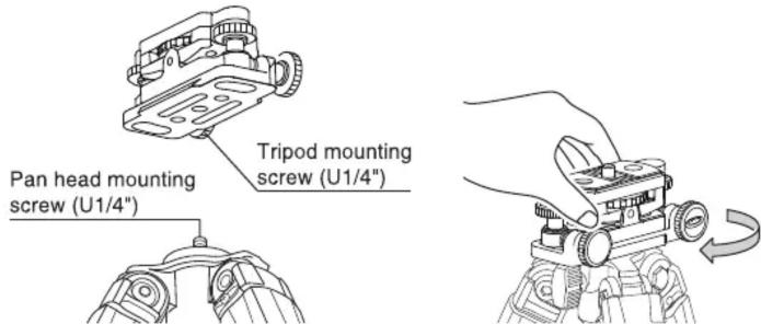
When using the unit with a field scope, attach the unit directly to the tripod or to the pan head according to your usage.
When mounting the unit directly to the tripod, rotate the unit clockwise until it comes to stop.
When mounting the unit to the portable equatorial mount, place the unit directly to the tripod.
(mounting on the pan head)
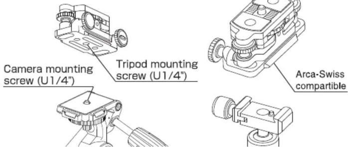
Insert pan head attachment screw of the pan head to the tripod mounting screw hole of the unit and firmly fix the unit.
Although the unit base is Arca-Swiss compatible, the unit may not mount to all Arca-Swiss compatible pan head.
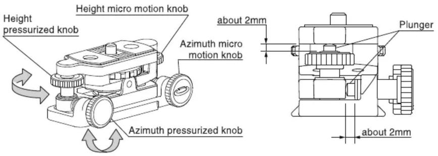
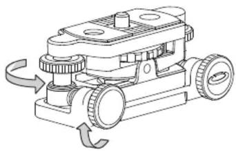
How to use micro motion knobs
natural_image
Technical line drawing of a mechanical device with rotating components and no visible text or symbolsAdjust the protrusion of each plunger about 2mm, by rotating both height and azimuth pressurizing knobs. When plunger comes out from the pressurizing screw, the micro motion knobs can be operated. In case of fine adjustment range is wide, adjust both the pressurizing knob until plunger retracts.
To lock the angle of the platform, rotate the pressurizing knob until plunger retracts. Rotate the pressurizing knob until it comes to stop. Do not overturn the knob.
Install the portable equatorial mount (at Northern Hemisphere)
natural_image
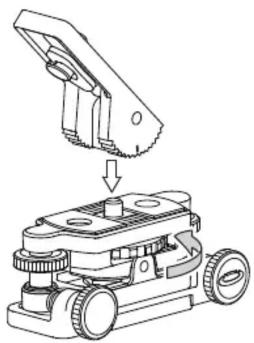
Technical line drawing of a mechanical device with a component being inserted (no text or symbols)Rotate wedge mounting dial to mount the wedge to the main body. Engage the grooves of the main body and the wedge.
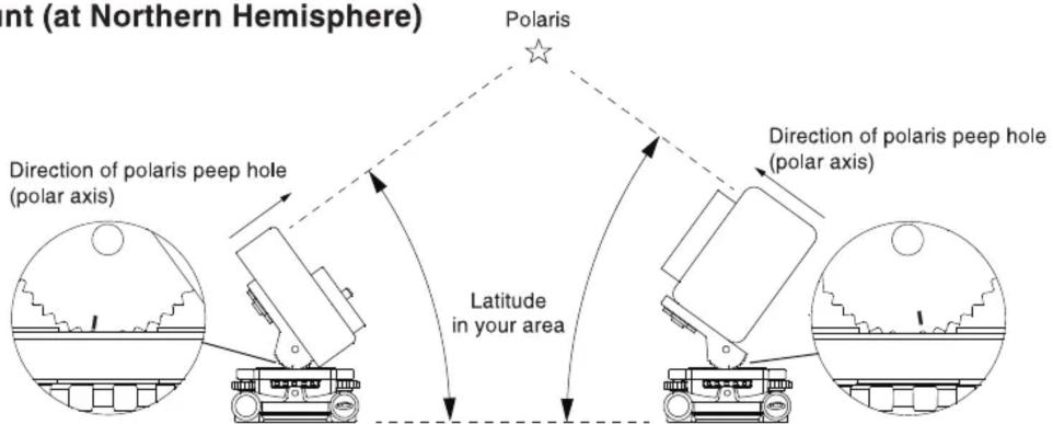
The indicator can be a good reference mark for easy and quick wedge angle setting. It is good to know beforehand how many steps need to be shifted from 45 deg. to achieve nearest wedge angle to the latitude of your area. The indicator is carved at 45 deg. position relative to the mounting surface of the wedge. And the angle of the wedge can be adjusted by 9 deg. increments. Adjust the angle of the wedge to match the latitude of your area.
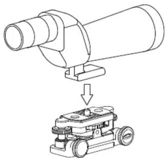
Install the field scope
natural_image
Diagram showing a mechanical device with a cylindrical component being processed by a robotic arm (no text or symbols present)Insert wedge mounting screw to the screw to the screw hole of the field scope and rotate the wedge mounting dial until it stop.
Center of gravity of the equipment
Caution
Depending on the position of the center of gravity of the product to be installed, the plunger may sink and the fine adjustment may not be performed correctly. In this case, reverse the mounting direction or shift the center of gravity of the equipment. Place the center of gravity to the side of the height micro motion knob.
Installation of astrophotography accessories
Caution
There are two each accessory holes on both top and bottom of the unit. (refer to Parts description) Top screw holes are M8 pitch 1.25, and M6 pitch 1 for the bottom. Both screw holes are 35mm interval. In case of installing a third-party accessory, the length of the screw to the pan head should be as follows.
M8 : less than 7mm M6 : less than 6mm
Care of the product
- DO NOT apply any grease or oil to this product.
- Clean with a mild detergent and a soft cloth only.
- DO NOT use close to flame. Avoid extreme heat.


Instruction manual and additional information Bedienungsanleitung und weitere Informationen Manuel d'instruction et informations complémentaires Manual de instrucciones e información adicional Handleiding en aanvullende informatie www.bresser.de/P4964140
Errors and technical changes reserved.
4964140